Page 4277 of 4647
SE-78
AUTOMATIC DRIVE POSITIONER
Revision: 2007 April2007 M35/M45
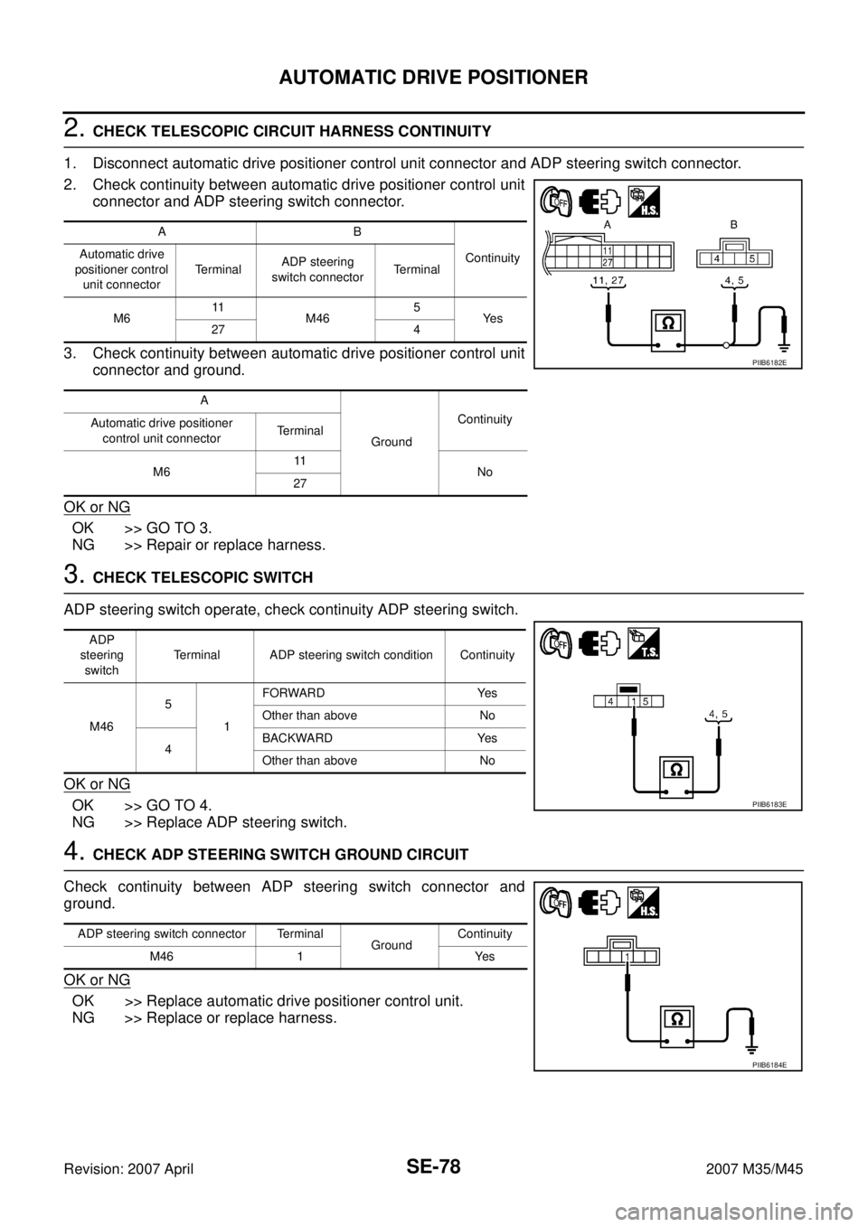
2. CHECK TELESCOPIC CIRCUIT HARNESS CONTINUITY
1. Disconnect automatic drive positioner control unit connector and ADP steering switch connector.
2. Check continuity between automatic drive positioner control unit
connector and ADP steering switch connector.
3. Check continuity between automatic drive positioner control unit
connector and ground.
OK or NG
OK >> GO TO 3.
NG >> Repair or replace harness.
3. CHECK TELESCOPIC SWITCH
ADP steering switch operate, check continuity ADP steering switch.
OK or NG
OK >> GO TO 4.
NG >> Replace ADP steering switch.
4. CHECK ADP STEERING SWITCH GROUND CIRCUIT
Check continuity between ADP steering switch connector and
ground.
OK or NG
OK >> Replace automatic drive positioner control unit.
NG >> Replace or replace harness.
AB
Continuity Automatic drive
positioner control
unit connectorTe r m i n a lADP steering
switch connectorTerminal
M611
M465
Ye s
27 4
A
GroundContinuity
Automatic drive positioner
control unit connectorTerminal
M611
No
27
PIIB6182E
ADP
steering
switchTerminal ADP steering switch condition Continuity
M465
1FORWARD Yes
Other than above No
4BACKWARD Yes
Other than above No
PIIB6183E
ADP steering switch connector Terminal
GroundContinuity
M46 1 Yes
PIIB6184E
Page 4279 of 4647
SE-80
AUTOMATIC DRIVE POSITIONER
Revision: 2007 April2007 M35/M45
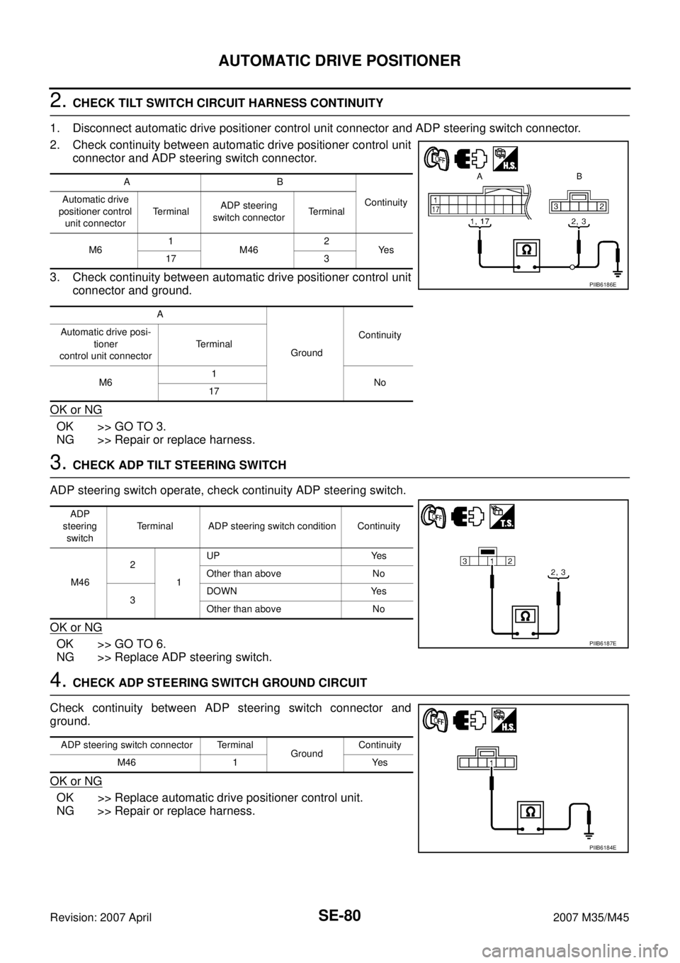
2. CHECK TILT SWITCH CIRCUIT HARNESS CONTINUITY
1. Disconnect automatic drive positioner control unit connector and ADP steering switch connector.
2. Check continuity between automatic drive positioner control unit
connector and ADP steering switch connector.
3. Check continuity between automatic drive positioner control unit
connector and ground.
OK or NG
OK >> GO TO 3.
NG >> Repair or replace harness.
3. CHECK ADP TILT STEERING SWITCH
ADP steering switch operate, check continuity ADP steering switch.
OK or NG
OK >> GO TO 6.
NG >> Replace ADP steering switch.
4. CHECK ADP STEERING SWITCH GROUND CIRCUIT
Check continuity between ADP steering switch connector and
ground.
OK or NG
OK >> Replace automatic drive positioner control unit.
NG >> Repair or replace harness.
AB
Continuity Automatic drive
positioner control
unit connectorTe r m i n a lADP steering
switch connectorTerminal
M61
M462
Ye s
17 3
A
GroundContinuity Automatic drive posi-
tioner
control unit connectorTerminal
M61
No
17
PIIB6186E
ADP
steering
switchTerminal ADP steering switch condition Continuity
M462
1UP Yes
Other than above No
3DOWN Yes
Other than above No
PIIB6187E
ADP steering switch connector Terminal
GroundContinuity
M46 1 Yes
PIIB6184E
Page 4285 of 4647
SE-86
AUTOMATIC DRIVE POSITIONER
Revision: 2007 April2007 M35/M45
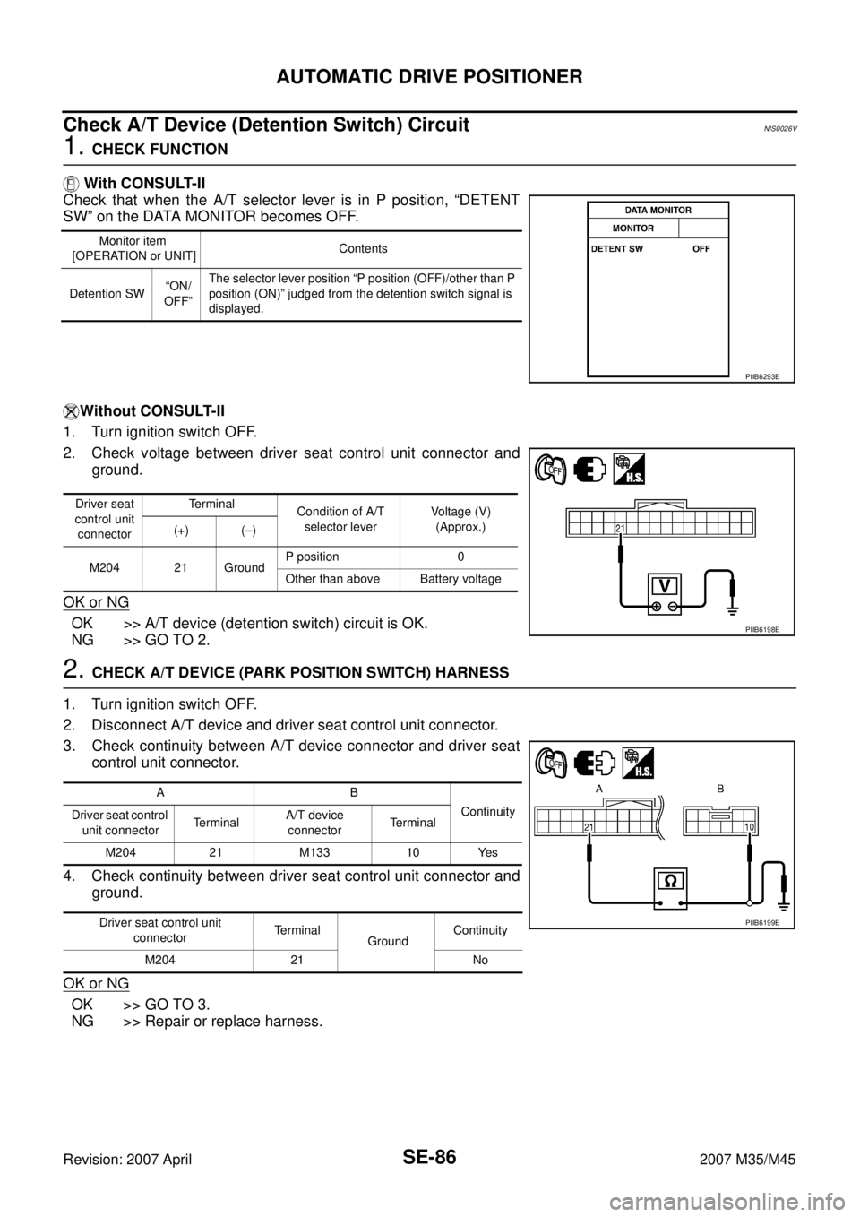
Check A/T Device (Detention Switch) Circuit NIS0026V
1. CHECK FUNCTION
With CONSULT-II
Check that when the A/T selector lever is in P position, “DETENT
SW” on the DATA MONITOR becomes OFF.
Without CONSULT-II
1. Turn ignition switch OFF.
2. Check voltage between driver seat control unit connector and
ground.
OK or NG
OK >> A/T device (detention switch) circuit is OK.
NG >> GO TO 2.
2. CHECK A/T DEVICE (PARK POSITION SWITCH) HARNESS
1. Turn ignition switch OFF.
2. Disconnect A/T device and driver seat control unit connector.
3. Check continuity between A/T device connector and driver seat
control unit connector.
4. Check continuity between driver seat control unit connector and
ground.
OK or NG
OK >> GO TO 3.
NG >> Repair or replace harness.
Monitor item
[OPERATION or UNIT]Contents
Detention SW“ON/
OFF”The selector lever position “P position (OFF)/other than P
position (ON)” judged from the detention switch signal is
displayed.
PIIB6293E
Driver seat
control unit
connectorTerminal
Condition of A/T
selector leverVoltage (V)
(Approx.)
(+) (–)
M204 21 GroundP position 0
Other than above Battery voltage
PIIB6198E
AB
Continuity
Driver seat control
unit connectorTe r m i n a lA/T device
connectorTerminal
M204 21 M133 10 Yes
Driver seat control unit
connectorTerminal
GroundContinuity
M204 21 No
PIIB6199E
Page 4286 of 4647

AUTOMATIC DRIVE POSITIONER
SE-87
C
D
E
F
G
H
J
K
L
MA
B
SE
Revision: 2007 April2007 M35/M45
3. CHECK PARK POSITION SWITCH
Check continuity between A/T device (detention switch) as follows.
OK or NG
OK >> Check the condition of the harness and the connector.
NG >> Replace A/T device.
Check Front Door Switch (Driver Side) Circuit NIS0026W
1. CHECK DOOR SWITCH INPUT SIGNAL
1. Turn ignition switch OFF.
2. Check voltage between BCM connector and ground.
OK or NG
OK >> Door switch circuit is OK.
NG >> GO TO 2.
2. CHECK HARNESS CONTINUITY
1. Turn ignition switch OFF.
2. Disconnect BCM and door switch (driver side) connector.
3. Check continuity between BCM connector and door switch (driver side) connector.
4. Check continuity between BCM connector ground.
OK or NG
OK >> GO TO 3.
NG >> Repair or replace harness.
A/T device Terminals Condition Continuity
M133 9 10P position Yes
Other than
P positionNo
PIIB6200E
Terminals
Door conditionVoltage (V)
(Approx.) (+)
(–)
BCM
connectorTerminal
M3 62 Ground Driver sideOPEN 0
CLOSE Battery voltage
PIIB6295E
AB
Continuity
BCM connector TerminalDoor switch
connectorTerminal
M3 62 B11 2 Yes
A
GroundContinuity
BCM connector Terminal
M3 62 No
PIIB6294E
Page 4287 of 4647
SE-88
AUTOMATIC DRIVE POSITIONER
Revision: 2007 April2007 M35/M45
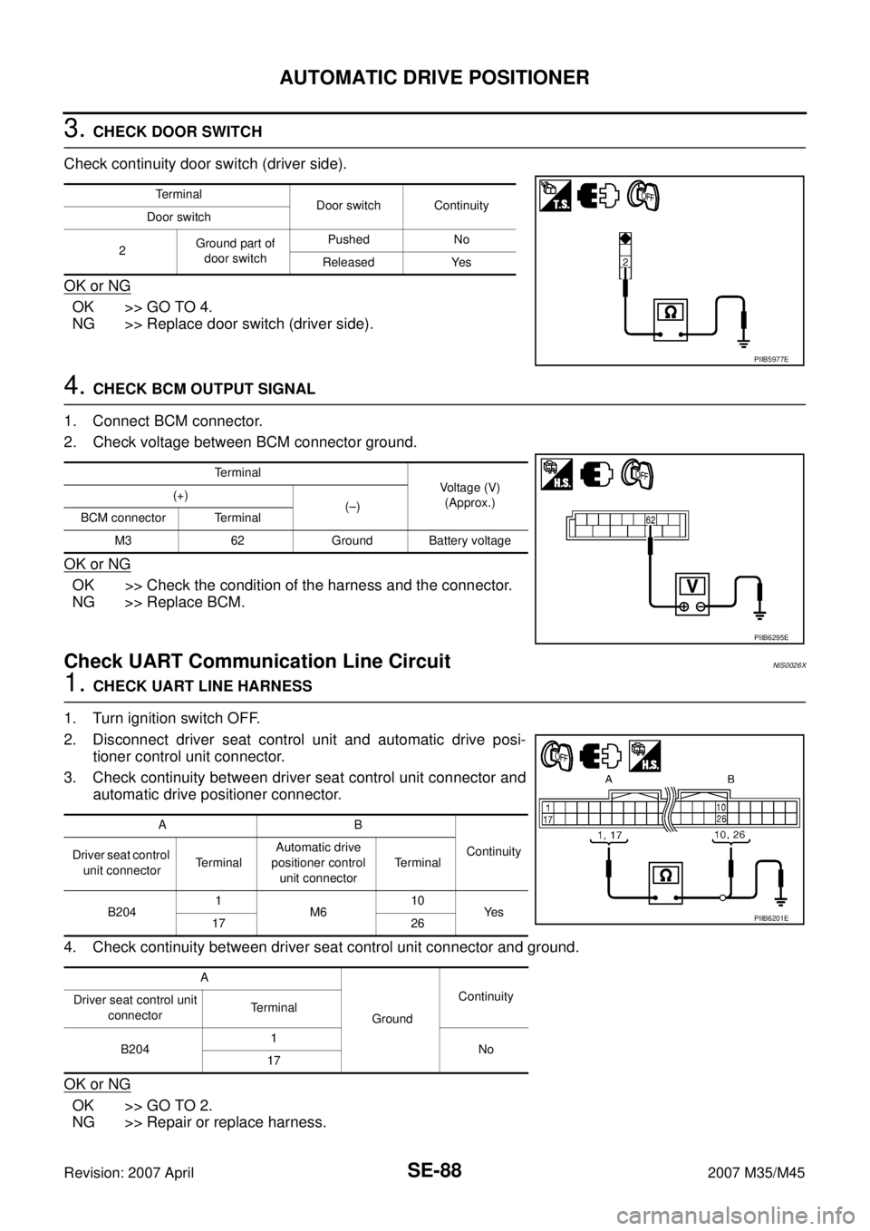
3. CHECK DOOR SWITCH
Check continuity door switch (driver side).
OK or NG
OK >> GO TO 4.
NG >> Replace door switch (driver side).
4. CHECK BCM OUTPUT SIGNAL
1. Connect BCM connector.
2. Check voltage between BCM connector ground.
OK or NG
OK >> Check the condition of the harness and the connector.
NG >> Replace BCM.
Check UART Communication Line Circuit NIS0026X
1. CHECK UART LINE HARNESS
1. Turn ignition switch OFF.
2. Disconnect driver seat control unit and automatic drive posi-
tioner control unit connector.
3. Check continuity between driver seat control unit connector and
automatic drive positioner connector.
4. Check continuity between driver seat control unit connector and ground.
OK or NG
OK >> GO TO 2.
NG >> Repair or replace harness.
Terminal
Door switch Continuity
Door switch
2Ground part of
door switchPushed No
Released Yes
PIIB5977E
Terminal
Voltage (V)
(Approx.) (+)
(–)
BCM connector Terminal
M3 62 Ground Battery voltage
PIIB6295E
AB
Continuity
Driver seat control
unit connectorTe r m i n a lAutomatic drive
positioner control
unit connectorTerminal
B2041
M610
Ye s
17 26
A
GroundContinuity
Driver seat control unit
connectorTerminal
B2041
No
17
PIIB6201E
Page 4289 of 4647
SE-90
AUTOMATIC DRIVE POSITIONER
Revision: 2007 April2007 M35/M45
OK or NG
OK >> Replace driver seat control unit.
NG >> Replace automatic drive positioner control unit.
Check Lumbar Support Circuit NIS0026Y
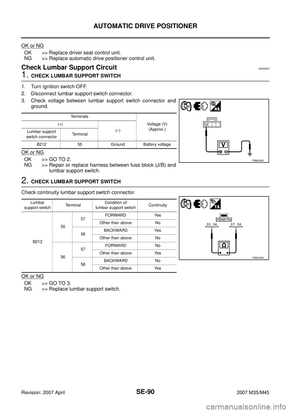
1. CHECK LUMBAR SUPPORT SWITCH
1. Turn ignition switch OFF.
2. Disconnect lumbar support switch connector.
3. Check voltage between lumbar support switch connector and
ground.
OK or NG
OK >> GO TO 2.
NG >> Repair or replace harness between fuse block (J/B) and
lumbar support switch.
2. CHECK LUMBAR SUPPORT SWITCH
Check continuity lumbar support switch connector.
OK or NG
OK >> GO TO 3.
NG >> Replace lumbar support switch.
Terminals
Voltage (V)
(Approx.) (+)
(–)
Lumbar support
switch connectorTerminal
B212 55 Ground Battery voltage
PIIB6204E
Lumbar
support switchTerminalCondition of
lumbar support switchContinuity
B2125557FORWARD Yes
Other than above No
58BACKWARD Yes
Other than above No
5657FORWARD No
Other than above Yes
58BACKWARD No
Other than above Yes
PIIB6205E
Page 4290 of 4647
AUTOMATIC DRIVE POSITIONER
SE-91
C
D
E
F
G
H
J
K
L
MA
B
SE
Revision: 2007 April2007 M35/M45
3. CHECK LUMBAR SUPPORT MOTOR HARNESS
1. Disconnect lumbar support motor connector.
2. Check continuity between lumbar support switch connector and
lumbar support motor connector.
3. Check continuity between lumbar support switch connector and
ground.
OK or NG
OK >> GO TO 4.
NG >> Repair or replace harness.
4. CHECK LUMBAR SUPPORT SWITCH GROUND CIRCUIT
Check continuity between lumbar support switch connector and
ground.
OK or NG
OK >> Check the condition of the harness and connector.
NG >> Repair or replace harness between lumbar support
switch and ground.
AB
Continuity
Lumbar support
switch connectorTerminalLumbar support
motor connectorTerminal
B21257
B21157
Ye s
58 58
A
GroundContinuity
Lumbar support switch
connectorTerminal
B21257
No
58
PIIB6206E
Lumbar support switch
connectorTerminal
GroundContinuity
B212 56 Yes
PIIB6207E
Page 4303 of 4647
SE-104
POWER SEAT(REAR)
Revision: 2007 April2007 M35/M45
Work FlowNIS00277
1. Check the symptom and customer's requests.
2. Understand the outline of system. Refer to SE-96, "
System Description" .
3. According to the trouble diagnosis chart, repair or replace the cause of the malfunction. Refer to SE-104,
"Trouble Diagnoses Symptom Chart" .
4. Does rear power seat operate normally? YES: GO TO 5, NO: GO TO 4.
5. INSPECTION END.
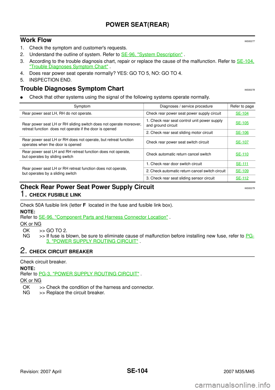
Trouble Diagnoses Symptom ChartNIS00278
�Check that other systems using the signal of the following systems operate normally.
Check Rear Power Seat Power Supply CircuitNIS00279
1. CHECK FUSIBLE LINK
Check 50A fusible link (letter F located in the fuse and fusible link box).
NOTE:
Refer to SE-96, "
Component Parts and Harness Connector Location" .
OK or NG
OK >> GO TO 2.
NG >> If fuse is blown, be sure to eliminate cause of malfunction before installing new fuse, refer to PG-
3, "POWER SUPPLY ROUTING CIRCUIT" .
2. CHECK CIRCUIT BREAKER
Check circuit breaker.
NOTE:
Refer to PG-3, "
POWER SUPPLY ROUTING CIRCUIT" .
OK or NG
OK >> Check the condition of the harness and connector.
NG >> Replace the circuit breaker.
Symptom Diagnoses / service procedure Refer to page
Rear power seat LH, RH do not operate. Check rear power seat power supply circuitSE-104
Rear power seat LH or RH sliding switch does not operate moreover,
retreat function does not operate if the door is opened1. Check rear seat control unit power supply
and ground circuit SE-105
2. Check rear seat sliding motor circuit SE-106
Rear power seat LH or RH does not operate, but retreat function
operates when the door is openedCheck rear power seat switch circuitSE-107
Rear power seat LH and RH retreat function does not operate,
but operates by sliding switchCheck automatic return cancel switchSE-110
Rear power seat LH or RH retreat function does not operate,
but operates by a sliding switch1. Check rear door switch circuitSE-1112. Check automatic return cancel switch circuit SE-109
3. Check rear seat sliding sensor circuitSE-112