Page 4305 of 4647
SE-106
POWER SEAT(REAR)
Revision: 2007 April2007 M35/M45
Check Rear Seat Sliding Motor CircuitNIS0027B
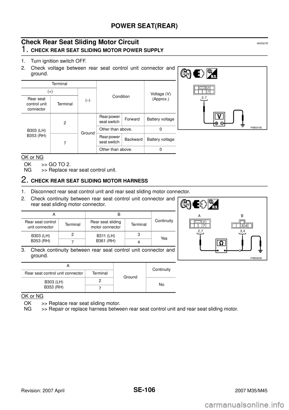
1. CHECK REAR SEAT SLIDING MOTOR POWER SUPPLY
1. Turn ignition switch OFF.
2. Check voltage between rear seat control unit connector and
ground.
OK or NG
OK >> GO TO 2.
NG >> Replace rear seat control unit.
2. CHECK REAR SEAT SLIDING MOTOR HARNESS
1. Disconnect rear seat control unit and rear seat sliding motor connector.
2. Check continuity between rear seat control unit connector and
rear seat sliding motor connector.
3. Check continuity between rear seat control unit connector and
ground.
OK or NG
OK >> Replace rear seat sliding motor.
NG >> Repair or replace harness between rear seat control unit and rear seat sliding motor.
Terminal
ConditionVoltage (V)
(Approx.) (+)
(–) Rear seat
control unit
connectorTerminal
B303 (LH)
B353 (RH)2
GroundRear power
seat switch Forward Battery voltage
Other than above. 0
7Rear power
seat switch Backward Battery voltage
Other than above. 0
PIIB5919E
AB
Continuity
Rear seat control
unit connectorTe r m i n a lRear seat sliding
motor connectorTerminal
B303 (LH)
B353 (RH)2
B311 (LH)
B361 (RH)3
Ye s
74
A
GroundContinuity
Rear seat control unit connector Terminal
B303 (LH)
B353 (RH)2
No
7
PIIB5920E
Page 4306 of 4647
POWER SEAT(REAR)
SE-107
C
D
E
F
G
H
J
K
L
MA
B
SE
Revision: 2007 April2007 M35/M45
Check Rear Power Seat Switch CircuitNIS0027C
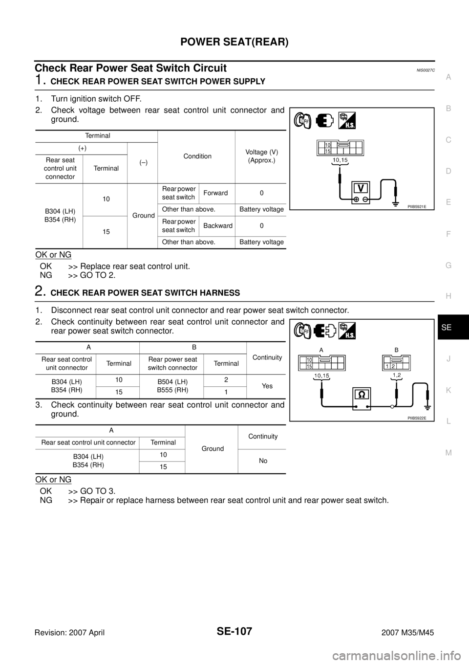
1. CHECK REAR POWER SEAT SWITCH POWER SUPPLY
1. Turn ignition switch OFF.
2. Check voltage between rear seat control unit connector and
ground.
OK or NG
OK >> Replace rear seat control unit.
NG >> GO TO 2.
2. CHECK REAR POWER SEAT SWITCH HARNESS
1. Disconnect rear seat control unit connector and rear power seat switch connector.
2. Check continuity between rear seat control unit connector and
rear power seat switch connector.
3. Check continuity between rear seat control unit connector and
ground.
OK or NG
OK >> GO TO 3.
NG >> Repair or replace harness between rear seat control unit and rear power seat switch.
Terminal
ConditionVoltage (V)
(Approx.) (+)
(–) Rear seat
control unit
connectorTerminal
B304 (LH)
B354 (RH)10
GroundRear power
seat switch Forward 0
Other than above. Battery voltage
15Rear power
seat switch Backward 0
Other than above. Battery voltage
PIIB5921E
AB
Continuity
Rear seat control
unit connectorTerminalRear power seat
switch connectorTerminal
B304 (LH)
B354 (RH)10
B504 (LH)
B555 (RH)2
Ye s
15 1
A
GroundContinuity
Rear seat control unit connector Terminal
B304 (LH)
B354 (RH)10
No
15
PIIB5922E
Page 4307 of 4647
SE-108
POWER SEAT(REAR)
Revision: 2007 April2007 M35/M45
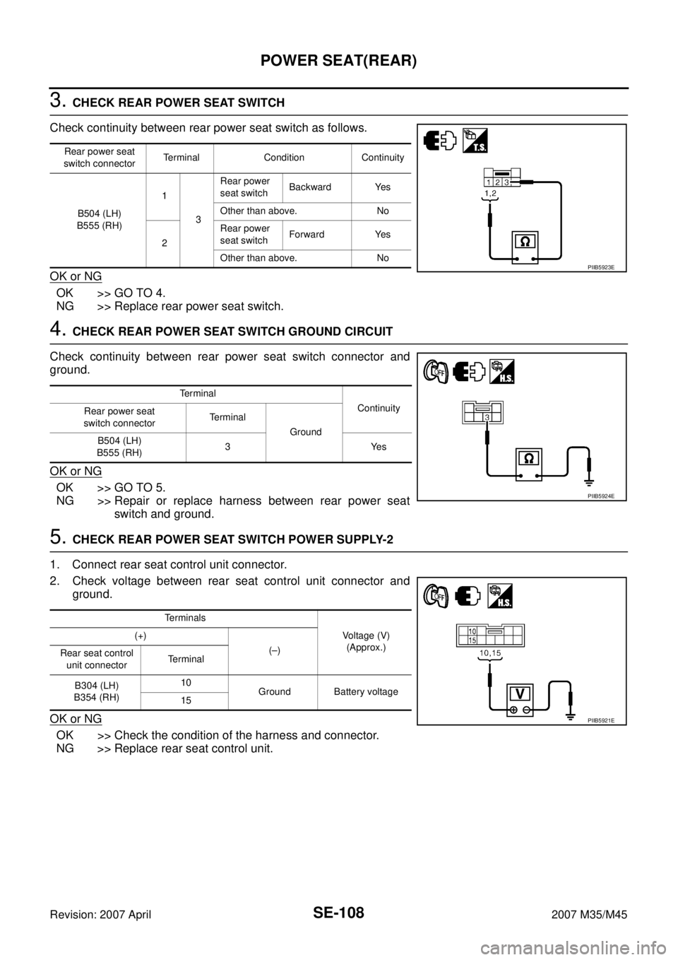
3. CHECK REAR POWER SEAT SWITCH
Check continuity between rear power seat switch as follows.
OK or NG
OK >> GO TO 4.
NG >> Replace rear power seat switch.
4. CHECK REAR POWER SEAT SWITCH GROUND CIRCUIT
Check continuity between rear power seat switch connector and
ground.
OK or NG
OK >> GO TO 5.
NG >> Repair or replace harness between rear power seat
switch and ground.
5. CHECK REAR POWER SEAT SWITCH POWER SUPPLY-2
1. Connect rear seat control unit connector.
2. Check voltage between rear seat control unit connector and
ground.
OK or NG
OK >> Check the condition of the harness and connector.
NG >> Replace rear seat control unit.
Rear power seat
switch connectorTerminal Condition Continuity
B504 (LH)
B555 (RH)1
3Rear power
seat switch Backward Yes
Other than above. No
2Rear power
seat switch Forward Yes
Other than above. No
PIIB5923E
Te r m i n a l
Continuity
Rear power seat
switch connectorTerminal
Ground
B504 (LH)
B555 (RH)3Yes
PIIB5924E
Terminals
Voltage (V)
(Approx.) (+)
(–)
Rear seat control
unit connectorTerminal
B304 (LH)
B354 (RH)10
Ground Battery voltage
15
PIIB5921E
Page 4308 of 4647
POWER SEAT(REAR)
SE-109
C
D
E
F
G
H
J
K
L
MA
B
SE
Revision: 2007 April2007 M35/M45
Check Automatic Return Cancel Switch CircuitNIS0027D
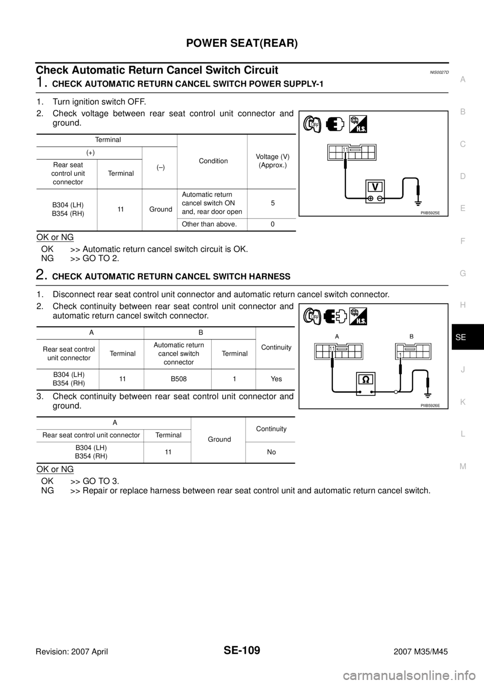
1. CHECK AUTOMATIC RETURN CANCEL SWITCH POWER SUPPLY-1
1. Turn ignition switch OFF.
2. Check voltage between rear seat control unit connector and
ground.
OK or NG
OK >> Automatic return cancel switch circuit is OK.
NG >> GO TO 2.
2. CHECK AUTOMATIC RETURN CANCEL SWITCH HARNESS
1. Disconnect rear seat control unit connector and automatic return cancel switch connector.
2. Check continuity between rear seat control unit connector and
automatic return cancel switch connector.
3. Check continuity between rear seat control unit connector and
ground.
OK or NG
OK >> GO TO 3.
NG >> Repair or replace harness between rear seat control unit and automatic return cancel switch.
Terminal
ConditionVoltage (V)
(Approx.) (+)
(–) Rear seat
control unit
connectorTe r m i n a l
B304 (LH)
B354 (RH)11 GroundAutomatic return
cancel switch ON
and, rear door open5
Other than above. 0
PIIB5925E
AB
Continuity
Rear seat control
unit connectorTerminalAutomatic return
cancel switch
connectorTerminal
B304 (LH)
B354 (RH)11 B508 1 Yes
A
GroundContinuity
Rear seat control unit connector Terminal
B304 (LH)
B354 (RH)11 N o
PIIB5926E
Page 4309 of 4647
SE-110
POWER SEAT(REAR)
Revision: 2007 April2007 M35/M45
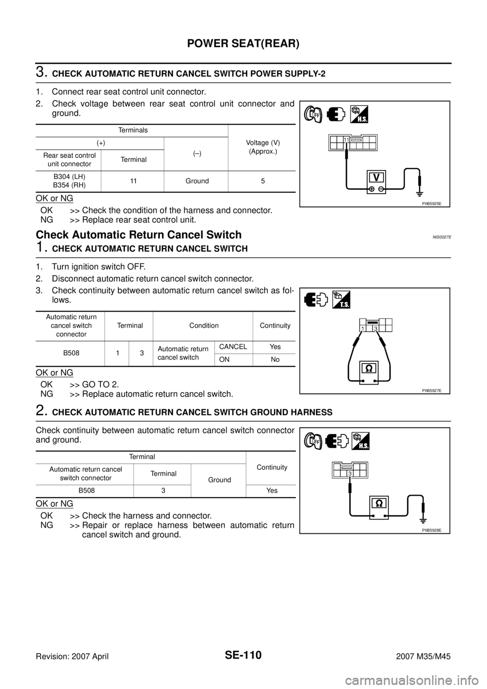
3. CHECK AUTOMATIC RETURN CANCEL SWITCH POWER SUPPLY-2
1. Connect rear seat control unit connector.
2. Check voltage between rear seat control unit connector and
ground.
OK or NG
OK >> Check the condition of the harness and connector.
NG >> Replace rear seat control unit.
Check Automatic Return Cancel SwitchNIS0027E
1. CHECK AUTOMATIC RETURN CANCEL SWITCH
1. Turn ignition switch OFF.
2. Disconnect automatic return cancel switch connector.
3. Check continuity between automatic return cancel switch as fol-
lows.
OK or NG
OK >> GO TO 2.
NG >> Replace automatic return cancel switch.
2. CHECK AUTOMATIC RETURN CANCEL SWITCH GROUND HARNESS
Check continuity between automatic return cancel switch connector
and ground.
OK or NG
OK >> Check the harness and connector.
NG >> Repair or replace harness between automatic return
cancel switch and ground.
Terminals
Voltage (V)
(Approx.) (+)
(–)
Rear seat control
unit connectorTerminal
B304 (LH)
B354 (RH)11 Ground 5
PIIB5925E
Automatic return
cancel switch
connectorTerminal Condition Continuity
B508 1 3Automatic return
cancel switchCANCEL Yes
ON No
PIIB5927E
Te r m i n a l
Continuity
Automatic return cancel
switch connectorTerminal
Ground
B508 3 Yes
PIIB5928E
Page 4310 of 4647
POWER SEAT(REAR)
SE-111
C
D
E
F
G
H
J
K
L
MA
B
SE
Revision: 2007 April2007 M35/M45
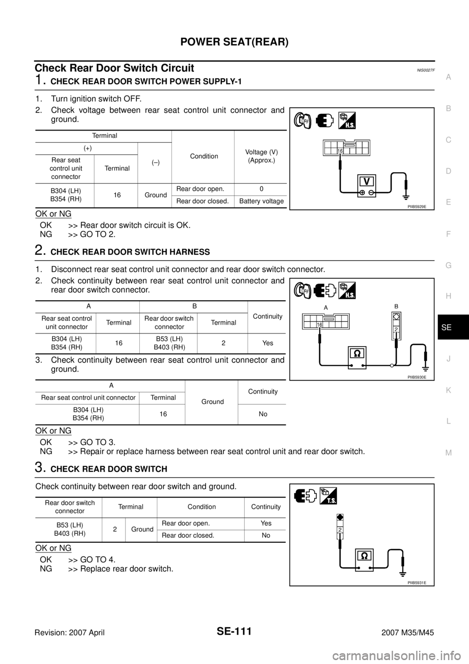
Check Rear Door Switch CircuitNIS0027F
1. CHECK REAR DOOR SWITCH POWER SUPPLY-1
1. Turn ignition switch OFF.
2. Check voltage between rear seat control unit connector and
ground.
OK or NG
OK >> Rear door switch circuit is OK.
NG >> GO TO 2.
2. CHECK REAR DOOR SWITCH HARNESS
1. Disconnect rear seat control unit connector and rear door switch connector.
2. Check continuity between rear seat control unit connector and
rear door switch connector.
3. Check continuity between rear seat control unit connector and
ground.
OK or NG
OK >> GO TO 3.
NG >> Repair or replace harness between rear seat control unit and rear door switch.
3. CHECK REAR DOOR SWITCH
Check continuity between rear door switch and ground.
OK or NG
OK >> GO TO 4.
NG >> Replace rear door switch.
Terminal
ConditionVoltage (V)
(Approx.) (+)
(–) Rear seat
control unit
connectorTe r m i n a l
B304 (LH)
B354 (RH)16 GroundRear door open. 0
Rear door closed. Battery voltage
PIIB5929E
AB
Continuity
Rear seat control
unit connectorTerminalRear door switch
connectorTerminal
B304 (LH)
B354 (RH)16B53 (LH)
B403 (RH)2 Yes
A
GroundContinuity
Rear seat control unit connector Terminal
B304 (LH)
B354 (RH)16 No
PIIB5930E
Rear door switch
connectorTerminal Condition Continuity
B53 (LH)
B403 (RH)2 GroundRear door open. Yes
Rear door closed. No
PIIB5931E
Page 4324 of 4647
CLIMATE CONTROLLED SEAT
SE-125
C
D
E
F
G
H
J
K
L
MA
B
SE
Revision: 2007 April2007 M35/M45
Work FlowNIS0027M
1. Check the symptom and customer's requests.
2. Understand the outline of system. Refer to SE-114, "
System Description" .
3. Perform the preliminary check. Refer toSE-126, "
Preliminary Check" .
4. According to the trouble diagnosis chart, repair or replace the cause of the malfunction. Refer to SE-126,
"Trouble Diagnoses Symptom Chart" .
5. Does climate controlled seat operate normally? YES: GO TO 6, NO: GO TO 4.
6. INSPECTION END.
23 L/RSeatback thermal electric device
sensor signalInputBlower motor operated 0.5 – 4
Ignition switch OFF 0
24 LSeatback thermal electric device
sensor ground— Ignition switch ON 0 Te r -
minalWire
ColorItemSignal
Input/
OutputConditionVoltage (V)
(Approx)
Page 4326 of 4647
CLIMATE CONTROLLED SEAT
SE-127
C
D
E
F
G
H
J
K
L
MA
B
SE
Revision: 2007 April2007 M35/M45
Check Climate Controlled Seat Control Unit Power Supply Circuit NIS0027P
1. CHECK FUSE
Check 10A fuse [No. 12, located in fuse block (J/B)]
NOTE:
Refer to SE-114, "
Component Parts and Harness Connector Location" .
OK or NG
OK >> GO TO 2.
NG >> If fuse is blown, be sure to eliminate cause of malfunction before installing new fuse, refer to PG-
3, "POWER SUPPLY ROUTING CIRCUIT" .
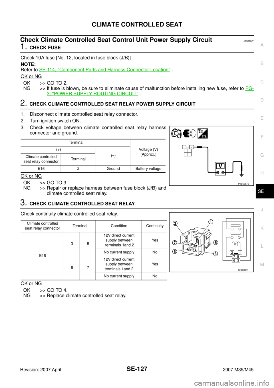
2. CHECK CLIMATE CONTROLLED SEAT RELAY POWER SUPPLY CIRCUIT
1. Disconnect climate controlled seat relay connector.
2. Turn ignition switch ON.
3. Check voltage between climate controlled seat relay harness
connector and ground.
OK or NG
OK >> GO TO 3.
NG >> Repair or replace harness between fuse block (J/B) and
climate controlled seat relay.
3. CHECK CLIMATE CONTROLLED SEAT RELAY
Check continuity climate controlled seat relay.
OK or NG
OK >> GO TO 4.
NG >> Replace climate controlled seat relay.
Terminal
Voltage (V)
(Approx.) (+)
(–)
Climate controlled
seat relay connectorTerminal
E16 2 Ground Battery voltage
PIIB6067E
Climate controlled
seat relay connectorTerminal Condition Continuity
E163512V direct current
supply between
terminals 1and 2Ye s
No current supply No
6712V direct current
supply between
terminals 1and 2Ye s
No current supply No
SEC202B