Page 1177 of 4647
BL-244
IVIS (INFINITI VEHICLE IMMOBILIZER SYSTEM-NATS)
Revision: 2007 April2007 M35/M45
IVIS (INFINITI VEHICLE IMMOBILIZER SYSTEM-NATS)PFP:28591
Component Parts and Harness Connector LocationNIS0020C
1. Fuse block (J/B) fuse layout 2. Fuse and fusible link box 3. BCM M1, M2, M3 (View with instru-
ment lower panel RH removed)
4. Intelligent key unit M32, M33 (View
with dash side finisher LH removed) 5. PDU M30, M31 (View with combina-
tion meter removed)6. IPDM E/R E4, E9
(Engine room)
7. ECM M71 (View with instrument
lower panel RH removed)8. Push-button ignition switch M27 9. Stop lamp switch E124
PIIB5894E
Page 1214 of 4647

BODY REPAIR
BL-281
C
D
E
F
G
H
J
K
L
MA
B
BL
Revision: 2007 April2007 M35/M45
BODY REPAIRPFP:60100
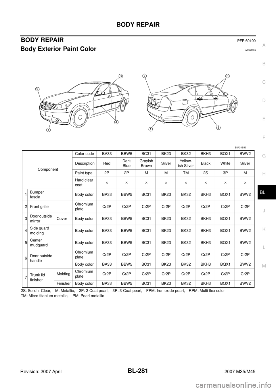
Body Exterior Paint ColorNIS0020X
2S: Solid + Clear, M: Metallic, 2P: 2-Coat pearl, 3P: 3-Coat pearl, FPM: Iron oxide pearl, RPM: Multi flex color
TM: Micro titanium metallic, PM: Pearl metallic ComponentColor code BA33 BBW5 BC31 BK23 BK32 BKH3 BQX1 BWV2
Description RedDark
BlueGrayish
BrownSilverYe l l o w -
ish SilverBlack White Silver
Paint type 2P 2P M M TM 2S 3P M
Hard clear
coat××××××××
1Bumper
fasciaBody color BA33 BBW5 BC31 BK23 BK32 BKH3 BQX1 BWV2
2 Front grilleChromium
plateCr2P Cr2P Cr2P Cr2P Cr2P Cr2P Cr2P Cr2P
3Door outside
mirrorCover Body color BA33 BBW5 BC31 BK23 BK32 BKH3 BQX1 BWV2
4Side guard
moldingBody color BA33 BBW5 BC31 BK23 BK32 BKH3 BQX1 BWV2
5Center
mudguardBody color BA33 BBW5 BC31 BK23 BK32 BKH3 BQX1 BWV2
6Door outside
handleChromium
plateCr2P Cr2P Cr2P Cr2P Cr2P Cr2P Cr2P Cr2P
Body color BA33 BBW5 BC31 BK23 BK32 BKH3 BQX1 BWV2
7Trunk lid
finisherMoldingChromium
plateCr2P Cr2P Cr2P Cr2P Cr2P Cr2P Cr2P Cr2P
Finisher Body color BA33 BBW5 BC31 BK23 BK32 BKH3 BQX1 BWV2
SIIA2451E
Page 1215 of 4647
BL-282
BODY REPAIR
Revision: 2007 April2007 M35/M45
Body Component PartsNIS0020Y
UNDERBODY COMPONENT PARTS
SIIA2736E
Page 1217 of 4647
BL-284
BODY REPAIR
Revision: 2007 April2007 M35/M45
BODY COMPONENT PARTS
SIIA2453E
Page 1219 of 4647

BL-286
BODY REPAIR
Revision: 2007 April2007 M35/M45
Corrosion ProtectionNIS0020Z
DESCRIPTION
To provide improved corrosion prevention, the following anti-corrosive measures have been implemented in
NISSAN production plants. When repairing or replacing body panels, it is necessary to use the same anti-cor-
rosive measures.
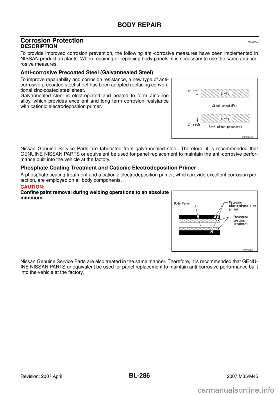
Anti-corrosive Precoated Steel (Galvannealed Steel)
To improve repairability and corrosion resistance, a new type of anti-
corrosive precoated steel sheet has been adopted replacing conven-
tional zinc-coated steel sheet.
Galvannealed steel is electroplated and heated to form Zinc-iron
alloy, which provides excellent and long term corrosion resistance
with cationic electrodeposition primer.
Nissan Genuine Service Parts are fabricated from galvannealed steel. Therefore, it is recommended that
GENUINE NISSAN PARTS or equivalent be used for panel replacement to maintain the anti-corrosive perfor-
mance built into the vehicle at the factory.
Phosphate Coating Treatment and Cationic Electrodeposition Primer
A phosphate coating treatment and a cationic electrodeposition primer, which provide excellent corrosion pro-
tection, are employed on all body components.
CAUTION:
Confine paint removal during welding operations to an absolute
minimum.
Nissan Genuine Service Parts are also treated in the same manner. Therefore, it is recommended that GENU-
INE NISSAN PARTS or equivalent be used for panel replacement to maintain anti-corrosive performance built
into the vehicle at the factory.
SIIA2294E
PIIA0095E
Page 1239 of 4647
BL-306
BODY REPAIR
Revision: 2007 April2007 M35/M45
Precautions in Repairing High Strength SteelNIS00214
High strength steel is used for body panels in order to reduce vehicle weight.
Accordingly, precautions in repairing automotive bodies made of high strength steel are described below:
HIGH STRENGTH STEEL (HSS) USED IN NISSAN VEHICLES
SP130 is the most commonly used HSS.
SP150 HSS is used only on parts that require much more strength.Tensile strength Nissan/Infiniti designation Major applicable parts
373 N/mm
2
(38kg/mm2 ,54klb/sq in)SP130
�Front & rear side member assembly
�Front side member closing plate assembly
�Front strut housing
�Lower dash
�Rear seat crossmember
�Other reinforcements
785-1350 N/mm
2
(80-138kg/mm2 , 114-196klb/sq in)SP150
�Center pillar reinforcement
(Component part)
�Outer roof side rail reinforcement
(Component part)
Page 1240 of 4647

BODY REPAIR
BL-307
C
D
E
F
G
H
J
K
L
MA
B
BL
Revision: 2007 April2007 M35/M45
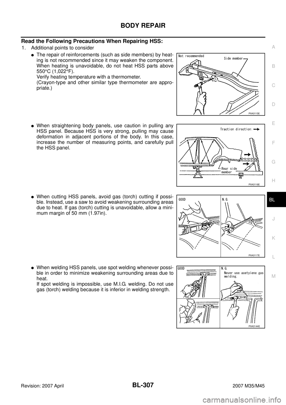
Read the Following Precautions When Repairing HSS:
1. Additional points to consider
�The repair of reinforcements (such as side members) by heat-
ing is not recommended since it may weaken the component.
When heating is unavoidable, do not heat HSS parts above
550°C (1,022°F).
Verify heating temperature with a thermometer.
(Crayon-type and other similar type thermometer are appro-
priate.)
�When straightening body panels, use caution in pulling any
HSS panel. Because HSS is very strong, pulling may cause
deformation in adjacent portions of the body. In this case,
increase the number of measuring points, and carefully pull
the HSS panel.
�When cutting HSS panels, avoid gas (torch) cutting if possi-
ble. Instead, use a saw to avoid weakening surrounding areas
due to heat. If gas (torch) cutting is unavoidable, allow a mini-
mum margin of 50 mm (1.97in).
�When welding HSS panels, use spot welding whenever possi-
ble in order to minimize weakening surrounding areas due to
heat.
If spot welding is impossible, use M.I.G. welding. Do not use
gas (torch) welding because it is inferior in welding strength.
PIIA0115E
PIIA0116E
PIIA0117E
PIIA0144E
Page 1268 of 4647

BR-1
BRAKE SYSTEM
F BRAKES
CONTENTS
C
D
E
G
H
I
J
K
L
M
SECTION BR
A
B
BR
Revision: 2007 April2007 M35/M45
BRAKE SYSTEM
PRECAUTIONS .......................................................... 3
Precautions for Supplemental Restraint System
(SRS) “AIR BAG” and “SEAT BELT PRE-TEN-
SIONER” .................................................................. 3
Precautions for Procedures without Cowl Top Cover ..... 3
Precautions for Brake System .................................. 3
PREPARATION ........................................................... 4
Commercial Service Tools ........................................ 4
NOISE, VIBRATION AND HARSHNESS (NVH)
TROUBLESHOOTING ................................................ 5
NVH Troubleshooting Chart ..................................... 5
BRAKE PEDAL .......................................................... 6
Inspection and Adjustment ....................................... 6
ADJUSTMENT ...................................................... 6
Removal and Installation .......................................... 7
COMPONENTS .................................................... 7
REMOVAL ............................................................. 8
INSPECTION AFTER REMOVAL ......................... 8
INSTALLATION ..................................................... 8
BRAKE FLUID ............................................................ 9
On-Board Inspection ................................................ 9
CHECKING BRAKE FLUID LEVEL ...................... 9
Checking Brake Line ................................................ 9
Drain and Refill ......................................................... 9
Bleeding Brake System .......................................... 10
BRAKE TUBE AND HOSE ........................................11
Hydraulic Circuit ...................................................... 11
Removal and Installation of Front Brake Tube and
Brake Hose ............................................................ 12
REMOVAL ........................................................... 12
INSTALLATION ................................................... 12
Removal and Installation of Rear Brake Tube and
Brake Hose ............................................................ 12
REMOVAL ........................................................... 12
INSTALLATION ................................................... 13
Inspection after Installation .................................... 13
BRAKE MASTER CYLINDER .................................. 14
On-Board Inspection .............................................. 14
LEAK INSPECTION ............................................ 14
Removal and Installation ........................................ 14REMOVAL ........................................................... 14
INSTALLATION ................................................... 14
Disassembly and Assembly .................................... 15
COMPONENTS ................................................... 15
DISASSEMBLY ................................................... 15
ASSEMBLY ......................................................... 16
BRAKE BOOSTER ................................................... 17
On-Board Inspection and Service ........................... 17
OPERATION CHECK .......................................... 17
AIR TIGHT CHECK ............................................. 17
Removal and Installation ........................................ 18
COMPONENTS ................................................... 18
REMOVAL ........................................................... 18
INSTALLATION ................................................... 18
VACUUM LINES ....................................................... 20
Components ........................................................... 20
Removal and Installation ........................................ 21
Inspection ............................................................... 21
VISUAL INSPECTION ......................................... 21
CHECK VALVE INSPECTION ............................. 21
FRONT DISC BRAKE ............................................... 22
On-Board Inspection ............................................... 22
PAD WEAR INSPECTION ................................... 22
Components ........................................................... 22
Removal and Installation of Brake Pad .................. 23
REMOVAL ........................................................... 23
INSTALLATION ................................................... 23
Removal and Installation of Brake Caliper Assembly
... 24
REMOVAL ........................................................... 24
INSTALLATION ................................................... 24
Disassembly and Assembly of Brake Caliper
Assembly ................................................................ 25
DISASSEMBLY ................................................... 25
INSPECTION AFTER DISASSEMBLY ................ 25
ASSEMBLY ......................................................... 26
DISC ROTOR INSPECTION ............................... 27
BRAKE BURNISHING PROCEDURE ................. 27
REAR DISC BRAKE ................................................. 28
On-Board Inspection ............................................... 28