Page 1286 of 4647
BRAKE BOOSTER
BR-19
C
D
E
G
H
I
J
K
L
MA
B
BR
Revision: 2007 April2007 M35/M45
4. Install brake pedal bracket mounting nuts and bolt, and tighten them to the specified torque. Refer to BR-
7, "COMPONENTS" .
5. Install vacuum hose into brake booster. Refer to BR-21, "
Removal and Installation" .
6. Install master cylinder to booster assembly. Refer to BR-14, "
Removal and Installation" .
7. Adjust the brake pedal height and the play of the brake pedal. Refer to BR-6, "
ADJUSTMENT" .
8. Tighten lock nut of input rod to the specified torque. Refer to BR-18, "
COMPONENTS" .
9. Connect front left brake tube to ABS actuator and electric unit (control unit). Refer to BR-11, "
Hydraulic
Circuit" .
10. Install cowl top. Refer to EI-18, "
Removal and Installation" .
11. Refill new brake fluid and bleed air. Refer to BR-10, "
Bleeding Brake System" .
Page 1287 of 4647
BR-20
VACUUM LINES
Revision: 2007 April2007 M35/M45
VACUUM LINESPFP:41920
ComponentsNFS000S9
VK45DE ENGINE MODELS
VQ35DE ENGINE MODELS
SFIA2957E
1. Clamp 2. Vacuum hose 3. Engine direction indicator stamp
(Built in check valve)
4. Clip 5. Vacuum piping 6. Grommet (Vacuum hose side)
7. Grommet (Cowl top assy side) 8. For intake manifold 9. For brake booster
SFIA2958E
1. Clamp 2. Vacuum hose 3. Engine direction indicator stamp
(Built in check valve)
4. Clip 5. Vacuum piping 6. Grommet (Vacuum hose side)
7. Grommet (Cowl top assy side) 8. For intake manifold 9. For brake booster
Page 1289 of 4647

BR-22
FRONT DISC BRAKE
Revision: 2007 April2007 M35/M45
FRONT DISC BRAKEPFP:41000
On-Board InspectionNFS000SC
PAD WEAR INSPECTION
�Check pad thickness from an inspection hole on cylinder body.
Check using a scale if necessary.
ComponentsNFS000SD
WARNING:
Clean dust on caliper and brake pad with a vacuum dust collector to minimize the hazard of air borne
particles or other materials.
CAUTION:
�While removing cylinder body, do not depress brake pedal because piston will pop out. Standard thickness : 11.0 mm (0.433 in)
Repair limit thickness : 2.0 mm (0.079 in)
MAA0439D
1. Union bolt 2. Copper washer 3. Brake hose
4. Cap 5. Bleed valve 6. Sliding pin bolt
7. Piston seal 8. Piston 9. Piston boot
10. Cylinder body 11. Sliding pin 12. Torque member mounting bolt
13. Washer 14. Sliding pin boot 15. Bushing
16. Torque member 17. Inner shim cover 18. Inner shim
19. Inner pad 20. Pad retainer 21. Pad wear sensor
22. Outer pad 23. Outer shim 24. Outer shim cover
Refer to GI-11, "
Components" and the followings for the symbols in the figure.
1: Apply rubber grease.
2: Apply PBC (Poly Butyl Cuprysil) grease or silicone-based grease.
3: Apply polyglycol ether based lubricant.
: Apply brake fluid.
PFIA0820E
Page 1290 of 4647

FRONT DISC BRAKE
BR-23
C
D
E
G
H
I
J
K
L
MA
B
BR
Revision: 2007 April2007 M35/M45
�It is not necessary to remove bolts on torque member and brake hose except for disassembly or
replacement of caliper assembly. In this case, hang cylinder body with a wire so as not to stretch
brake hose.
�Do not damage piston boot.
�If any shim is subject to serious corrosion, replace it with a new one.
�Always replace shim and shim cover as a set when replacing brake pads.
�Keep rotor free from brake fluid.
�Burnish the brake pads and disc rotor mutually contacting surfaces, after refinishing or replacing
rotors, after replacing pads, or if a soft pedal occurs at very low mileage. Refer to BR-27, "
BRAKE
BURNISHING PROCEDURE" .
Removal and Installation of Brake PadNFS000SE
REMOVAL
1. Remove tires from vehicle with power tool.
2. Remove lower sliding pin bolt.
3. Hang cylinder body with a wire, and remove pads, pad retainers,
shims, and shim cover from torque member.
CAUTION:
When removing the pad retainer from the torque member,
lift it in the direction indicated by the arrow in the figure so
that it does not deform.
INSTALLATION
1. Apply PBC (Poly Butyl Cuprysil) grease or silicone-based grease to between pad and shim. Install shim,
shim cover, to pad.
2. Apply PBC (Poly Butyl Cuprysil) grease or silicone-based
grease to between pad retainer and pad. Install pad retainers
and pads to torque member.
CAUTION:
�Securely assemble pad retainers so that they are not
being lifted up from torque member.
�Both inner and outer pads have a pad return system on
the pad retainer. Install pad return lever securely to pad
wear sensor.
3. Install cylinder body to torque member.
CAUTION:
In the case of replacing a pad with new one, check a brake fluid level in the reservoir tank because
brake fluid returns to master cylinder reservoir tank when pressing piston in.
NOTE:
Use a disc brake piston tool (commercial service tool) to easily press piston.
4. Install lower sliding pin bolt, and tighten it to the specified torque. Refer to BR-22, "
Components" .
5. Check front disc brake for drag.
6. Install tires to vehicle.
SBR556E
SBR557E
Page 1291 of 4647

BR-24
FRONT DISC BRAKE
Revision: 2007 April2007 M35/M45
Removal and Installation of Brake Caliper AssemblyNFS000SF
REMOVAL
1. Remove tires from vehicle with power tool.
2. Fasten disc rotor using wheel nut.
3. Drain brake fluid. Refer to BR-9, "
Drain and Refill" .
4. Remove union bolt, and then disconnect brake hose from caliper assembly.
5. Remove torque member mounting bolts, and remove brake cali-
per assembly.
CAUTION:
Do not drop brake pad.
6. Remove disc rotor.
CAUTION:
Put matching marks on wheel hub assembly and disc rotor,
if it is necessary to remove disc rotor.
INSTALLATION
CAUTION:
�Refill with new brake fluid “DOT 3”.
�Never reuse drained brake fluid.
1. Install disc rotor.
CAUTION:
Put alignment marks on disc rotor and wheel hub at the time of removal when reusing disc rotor.
2. Install brake caliper assembly to vehicle, and tighten torque member mounting bolts to the specified
torque. Refer to BR-22, "
Components" .
CAUTION:
Do not allow oil or any moisture on all contact surfaces between steering knuckle and caliper
assembly, bolts, and washer.
3. Install brake hose to brake caliper assembly, and tighten union
bolts to the specified torque. Refer to BR-12, "
Removal and
Installation of Front Brake Tube and Brake Hose" .
4. Refill with new brake fluid and bleed air. Refer to BR-10, "
Bleed-
ing Brake System" .
5. Check front disc brake for drag.
6. Install tires to vehicle.
SFIA2437E
SDIA2608E
SFIA2431E
Page 1293 of 4647

BR-26
FRONT DISC BRAKE
Revision: 2007 April2007 M35/M45
ASSEMBLY
1. Apply polyglycol ether based lubricant to piston seal, and install
them to cylinder body.
CAUTION:
Do not reuse piston seal.
2. Apply rubber grease to piston boot. Cover the piston end with
piston boot, and then install cylinder side lip on piston boot
securely into a groove on cylinder body.
CAUTION:
Do not reuse piston boot.
3. Apply brake fluid to piston. Push piston into cylinder body by
hand and push piston boot piston-side lip into the piston groove.
CAUTION:
Press the piston evenly and vary the pressing point to pre-
vent cylinder inner wall from being rubbed.
4. Install sliding pins and sliding pin boots to torque member.
5. Install torque member to steering knuckle, and tighten mounting bolts to the specified torque. Refer to BR-
22, "Components" .
CAUTION:
Do not allow oil or any moisture on all contact surfaces between steering knuckle and brake cali-
per assembly.
6. Press in piston until pads can be installed, and then install cylinder body to torque member.
7. Tighten sliding pin bolts to the specified torque. Refer to BR-22, "
Components" .
SFIA2399E
SFIA2432E
SFIA2279E
Page 1295 of 4647
BR-28
REAR DISC BRAKE
Revision: 2007 April2007 M35/M45
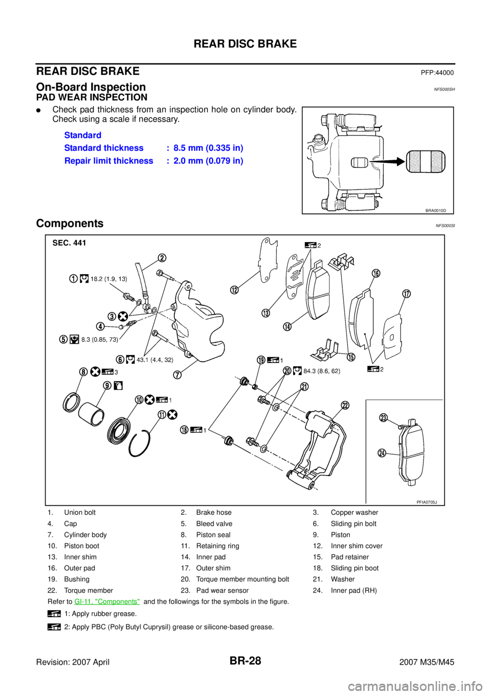
REAR DISC BRAKEPFP:44000
On-Board InspectionNFS000SH
PAD WEAR INSPECTION
�Check pad thickness from an inspection hole on cylinder body.
Check using a scale if necessary.
ComponentsNFS000SI
Standard
Standard thickness : 8.5 mm (0.335 in)
Repair limit thickness : 2.0 mm (0.079 in)
BRA0010D
1. Union bolt 2. Brake hose 3. Copper washer
4. Cap 5. Bleed valve 6. Sliding pin bolt
7. Cylinder body 8. Piston seal 9. Piston
10. Piston boot 11. Retaining ring 12. Inner shim cover
13. Inner shim 14. Inner pad 15. Pad retainer
16. Outer pad 17. Outer shim 18. Sliding pin boot
19. Bushing 20. Torque member mounting bolt 21. Washer
22. Torque member 23. Pad wear sensor 24. Inner pad (RH)
Refer to GI-11, "
Components" and the followings for the symbols in the figure.
1: Apply rubber grease.
2: Apply PBC (Poly Butyl Cuprysil) grease or silicone-based grease.
PFIA0705J
Page 1296 of 4647

REAR DISC BRAKE
BR-29
C
D
E
G
H
I
J
K
L
MA
B
BR
Revision: 2007 April2007 M35/M45
WARNING:
Clean dust on caliper and brake pad with a vacuum dust collector to minimize the hazard of air borne
particles or other materials.
CAUTION:
�While removing cylinder body, do not depress brake pedal because piston will pop out.
�It is not necessary to remove bolts on torque member and brake hose except for disassembly or
replacement of caliper assembly. In this case, hang cylinder body with a wire so as not to stretch
brake hose.
�Do not damage piston boot.
�If any shim is subject to serious corrosion, replace it with a new one.
�Always replace shim and shim covers as a set when replacing brake pads.
�Keep rotor free from brake fluid.
�Burnish the brake pads and disc rotor mutually contacting surfaces after refinishing or replacing
rotors, after replacing pads, or if a soft pedal occurs at very low mileage. Refer to BR-33, "
BRAKE
BURNISHING PROCEDURE" .
Removal and Installation of Brake PadNFS000SJ
REMOVAL
1. Remove tires from vehicle with power tool.
2. Remove lower sliding pin bolt.
3. Hang cylinder body with a wire, and remove pads, pad retainers, shims, and shim cover from torque mem-
ber.
CAUTION:
Deform pad retainer when removing pad retainer from torque member.
INSTALLATION
1. Apply PBC (Poly Butyl Cuprysil) grease or silicone-based grease to between pad and shim. Install inner
shim, inner shim cover to inner pad, and outer shim, outer shim cover to outer pad.
2. Install pad retainers and pads to torque member.
3. Press in piston until pads can be installed, and then install cylin-
der body to torque member.
CAUTION:
In the case of replacing a pad with new one, check a brake
fluid level in the reservoir tank because brake fluid returns
to master cylinder reservoir tank when pressing piston in.
NOTE:
Use a disc brake piston tool (commercial service tool) to easily
press piston.
4. Install upper sliding pin bolt and tighten to the specified torque.
Refer to BR-28, "
Components" .
5. Check rear disc brake for drag.
6. Install tires to vehicle.
3: Apply polyglycol ether based lubricant.
: Apply brake fluid.
PFIA0273E