2006 TOYOTA RAV4 ignition
[x] Cancel search: ignitionPage 1879 of 2000

LI–48LIGHTING – LIGHTING SYSTEM
LI
(b) Turn the ignition switch to the ON position and press the
intelligent tester main switch ON.
(c) Select the item below in the ACTIVE TEST and then
check the relay operation.
Main body ECU
OK:
Front fog light comes on.
OK
NG
(a) Check that the taillight comes on when the light control
switch is on (TAIL).
OK:
Taillight comes on.
NG
OK
(a) Remove the FR FOG fuse from the instrument panel
junction block.
(b) Measure the resistance of the fuses.
Standard resistance:
Below 1
NG
OK
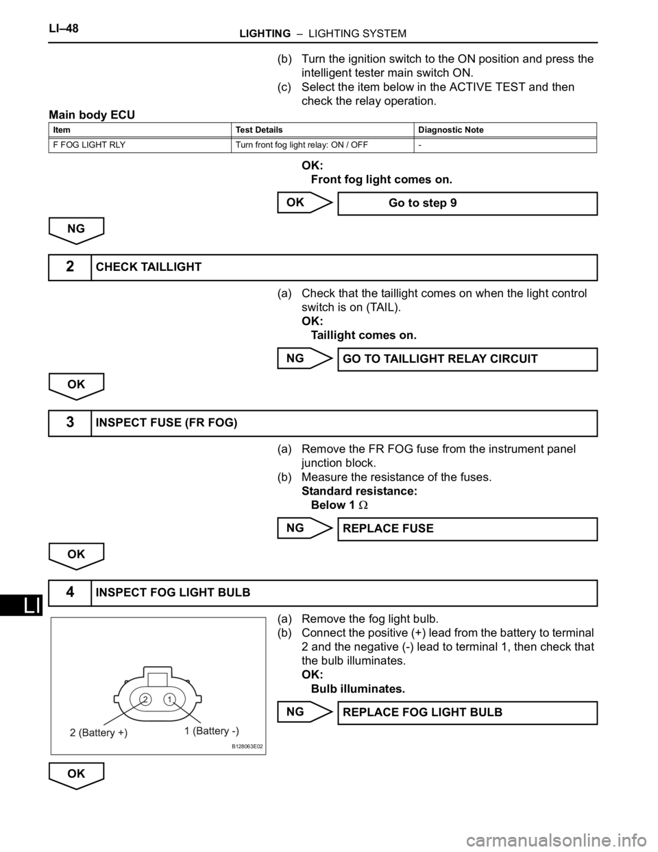
(a) Remove the fog light bulb.
(b) Connect the positive (+) lead from the battery to terminal
2 and the negative (-) lead to terminal 1, then check that
the bulb illuminates.
OK:
Bulb illuminates.
NG
OK
Item Test Details Diagnostic Note
F FOG LIGHT RLY Turn front fog light relay: ON / OFF -
Go to step 9
2CHECK TAILLIGHT
GO TO TAILLIGHT RELAY CIRCUIT
3INSPECT FUSE (FR FOG)
REPLACE FUSE
4INSPECT FOG LIGHT BULB
B128063E02
REPLACE FOG LIGHT BULB
Page 1903 of 2000

DOOR LOCK – POWER DOOR LOCK CONTROL SYSTEMDL–7
DL
OPERATION CHECK
1. CHECK ELECTRICAL DOOR LOCK OPERATION
(a) Check the basic function.
(1) Check that all doors lock when the door control
switch (for manual operation) is turned to LOCK
and all doors unlock when turned to UNLOCK.
(2) Check that all doors lock when the driver side
door lock key cylinder is turned to LOCK using
the key.
(3) Check that only the driver side door unlocks
when the driver side door lock key cylinder is
turned to UNLOCK and all doors unlock when
turned to UNLOCK once again within 3 seconds
using the key (2-step unlocking function).
(b) Check the key lock-in prevention.
NOTICE:
In order to prevent the key from being actually
locked-in, the inspection should be made with
the driver side door window open.
(1) Have the key inserted into the ignition key
cylinder.
(2) With the driver side door open, check that all
doors unlock immediately after the door lock
knob for the driver side door is turned to LOCK.
(3) With the driver side door open, check that all
doors unlock immediately after the door control
switch (for manual operation) is turned to LOCK.
(4) With the driver side door open, turn the driver
side door lock knob to LOCK and hold it for 2
seconds or more, and then close the driver side
door. Then check that all doors unlock.
Page 1908 of 2000

DL–12DOOR LOCK – POWER DOOR LOCK CONTROL SYSTEM
DL
ACT+ (IH-17) - Body
groundR - Body ground Door lock motor drive lock
outputDriver side door control
switch or passenger side
door control switch or
driver side door key
cylinder OFFBelow 1 V
ACT+ (IH-17) - Body
groundR - Body ground Door lock motor drive lock
outputDriver side door control
switch or passenger side
door control switch or
driver side door key
cylinder ON (LOCK)10 to 14 V
Below 1 V
ACT- (IA-4) - Body ground BR- Body ground Door lock motor drive
unlock outputDriver side door control
switch or passenger side
door control switch or
driver side door key
cylinder OFFBelow 1 V
ACT- (IA-4) - Body ground BR - Body ground Door lock motor drive
unlock outputDriver side door control
switch or passenger side
door control switch or
driver side door key
cylinder ON (UNLOCK)10 to 14 V
Below 1 V
ACT- (IH-18) - Body
groundB - Body ground Door lock motor drive
unlock outputDriver side door control
switch or passenger side
door control switch or
driver side door key
cylinder OFFBelow 1 V
ACT- (IH-18) - Body
groundB - Body ground Door lock motor drive
unlock outputDriver side door control
switch or passenger side
door control switch or
driver side door key
cylinder ON (UNLOCK)10 to 14 V
Below 1 V
KSW (IE-26) - Body
groundL- Body ground Key unlock warning switch
inputKey is inserted in ignition
key cylinderBelow 1 V
KSW (IE-26) - Body
groundL- Body ground Key unlock warning switch
inputNo key is in ignition key
cylinder10 to 14 V
UL1 (IH-5) - Body ground B - Body ground Driver side manual unlock
switch inputDriver side door control
switch OFFBelow 1 V
UL1 (IH-5) - Body ground B - Body ground Driver side manual unlock
switch inputDriver side door control
switch ON (UNLOCK)10 to 14 V
Below 1 V
UL1 (IH-14) - Body ground O - Body ground Passenger side manual
unlock switch inputPassenger side door
control switch OFFBelow 1 V
UL1 (IH-14) - Body ground O - Body ground Passenger side manual
unlock switch inputPassenger side door
control switch ON
(UNLOCK)10 to 14 V
Below 1 V
L1 (IH-4) - Body ground P - Body ground Driver side manual lock
switch inputDriver side door control
switch OFFBelow 1 V
L1 (IH-4) - Body ground P - Body ground Driver side manual lock
switch inputDriver side door control
switch ON (LOCK)10 to 14 V
Below 1 V
L1 (IH-13) - Body ground V - Body ground Passenger side manual
lock switch inputPassenger side door
control switch OFFBelow 1 V
L1 (IH-13) - Body ground V - Body ground Passenger side manual
lock switch inputPassenger side door
control switch ON (LOCK)10 to 14 V
Below 1 V
L2 (IH-7) - Body ground SB - Body ground Driver side Key-linked
operated lock switch inputDriver side door key
cylinder OFFBelow 1 V
L2 (IH-7) - Body ground SB - Body ground Driver side Key-linked
operated lock switch inputDriver side door key
cylinder ON (LOCK)10 to 14 V
Below 1 V
PCTY (IC-14) - Body
groundBR - Body ground Passenger door courtesy
switch inputPassenger side door
closed10 to 14 V
PCTY (IC-14) - Body
groundBR - Body ground Passenger door courtesy
switch inputPassenger side door open Below 1 V
RRCY (ID-7) - Body
groundLC - Body ground Rear door courtesy switch
LH inputRear RH door closed 10 to 14 V Symbols (Terminal No.) Wiring Color Terminal Description ConditionSpecified Condition
Page 1910 of 2000

DL–14DOOR LOCK – POWER DOOR LOCK CONTROL SYSTEM
DL
DIAGNOSIS SYSTEM
1. DESCRIPTION
Power door lock control system data can be read in the
Data Link Connector 3 (DLC3) of the vehicle. When the
system seems to be malfunctioning, use the intelligent
tester to check for malfunctions and perform repairs.
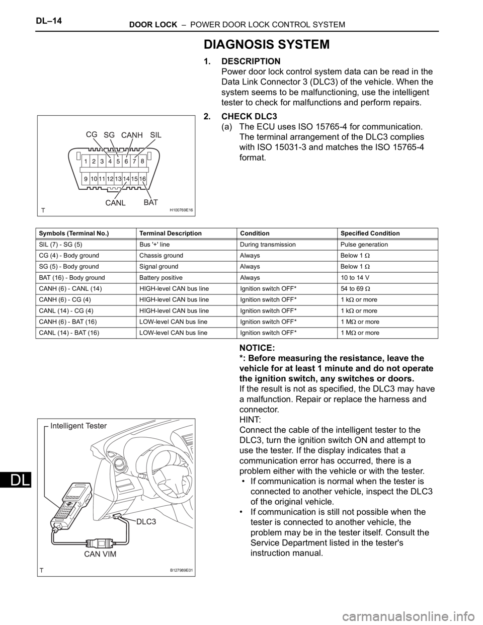
2. CHECK DLC3
(a) The ECU uses ISO 15765-4 for communication.
The terminal arrangement of the DLC3 complies
with ISO 15031-3 and matches the ISO 15765-4
format.
NOTICE:
*: Before measuring the resistance, leave the
vehicle for at least 1 minute and do not operate
the ignition switch, any switches or doors.
If the result is not as specified, the DLC3 may have
a malfunction. Repair or replace the harness and
connector.
HINT:
Connect the cable of the intelligent tester to the
DLC3, turn the ignition switch ON and attempt to
use the tester. If the display indicates that a
communication error has occurred, there is a
problem either with the vehicle or with the tester.
• If communication is normal when the tester is
connected to another vehicle, inspect the DLC3
of the original vehicle.
• If communication is still not possible when the
tester is connected to another vehicle, the
problem may be in the tester itself. Consult the
Service Department listed in the tester's
instruction manual.
H100769E16
Symbols (Terminal No.) Terminal Description Condition Specified Condition
SIL (7) - SG (5) Bus '+' line During transmission Pulse generation
CG (4) - Body ground Chassis ground Always Below 1
SG (5) - Body ground Signal ground Always Below 1
BAT (16) - Body ground Battery positive Always 10 to 14 V
CANH (6) - CANL (14) HIGH-level CAN bus line Ignition switch OFF*54 to 69
CANH (6) - CG (4) HIGH-level CAN bus line Ignition switch OFF* 1 k or more
CANL (14) - CG (4) HIGH-level CAN bus line Ignition switch OFF* 1 k
or more
CANH (6) - BAT (16) LOW-level CAN bus line Ignition switch OFF* 1 M
or more
CANL (14) - BAT (16) LOW-level CAN bus line Ignition switch OFF* 1 M
or more
B127989E01
Page 1911 of 2000

DOOR LOCK – POWER DOOR LOCK CONTROL SYSTEMDL–15
DL
DATA LIST / ACTIVE TEST
1. READ DATA LIST
HINT:
Using the intelligent tester's DATA LIST allows switch,
sensor, actuator and other item values to be read without
removing any parts. Reading the DATA LIST early in
troubleshooting is one way to save time.
(a) Connect the intelligent tester (with CAN VIM) to the
DLC3.
(b) Turn the ignition switch ON.
(c) Read the DATA LIST on the tester's screen.
Main body ECU
Item Measurement Item / Display
(Range)Normal Condition Diagnostic Note
D DOR CTY SW Driver side door courtesy light
switch signal / ON or OFFON: Driver side door is open
OFF: Driver side door is closed-
D LOCK POS SW Driver side door lock position
switch signal / ON or OFFON: Driver side door is unlocked
OFF: Driver side door is locked-
D/L SW-LOCK Door manual lock switch signal
ON or OFFON: Door control switch on power
window regulator master switch is
pushed to lock position
OFF: Door control switch on
power window regulator master
switch is not pushed-
D/L SW UNLOCK Door manual unlock switch signal
/ ON or OFFON: Door control switch on power
window regulator master switch is
pushed to unlock position
OFF: Door control switch on
power window regulator master
switch is not pushed-
DOR KEY SW-LOCK Door key linked lock switch signal
/ ON or OFFON: Driver side door key cylinder
is turned to lock position
OFF: Driver side door key
cylinder is not turned-
D DOR KEY SW-UL Door key linked lock switch signal
/ ON or OFFON: Driver side door key cylinder
is turned to unlock position
OFF: Driver side door key
cylinder is not turned-
P DOR CTY SW Passenger side door courtesy
light signal / ON or OFFON: Passenger side door is open
OFF: Passenger side door is
closed-
P LOCK POS SW Passenger side door lock position
switch signal / ON or OFFON: Passenger side door is
unlocked
OFF: Passenger side door is
locked-
RR DOR CTY SW Rear door RH courtesy light
switch signal / ON or OFFON: Rear door RH is open
OFF: Rear door RH is closed-
RL DOR CTY SW Rear door LH courtesy light
switch signal / ON or OFFON: Rear door LH is open
OFF: Rear door LH is closed-
BK DOR CTY SW Back door courtesy light switch
signal / ON or OFFON: Back door is open
OFF: Back door is closed-
KEY UNLK WRN SW Unlock warning switch signal /
ON or OFFON: Key is in ignition key cylinder
OFF: No key is in ignition key
cylinder-
Page 1912 of 2000

DL–16DOOR LOCK – POWER DOOR LOCK CONTROL SYSTEM
DL
2. PERFORM ACTIVE TEST
HINT:
Performing the intelligent tester's ACTIVE TEST allows
relay, VSV, actuator and other items to be operated
without removing any parts. Performing the ACTIVE
TEST early in troubleshooting is one way to save time.
The DATA LIST can be displayed during the ACTIVE
TEST.
(a) Connect the intelligent tester (with CAN VIM) to the
DLC3.
(b) Turn the ignition switch ON.
(c) Perform the ACTIVE TEST according to the display
on the tester.
Main body ECU
Item Test Details Diagnostic Note
DOOR LOCK Operate door lock motor
LOCK/UNLOCK-
D DOOR UNLOCK Operate driver side door unlock
ON / OFF-
Page 1933 of 2000

2AZ-FE ENGINE CONTROL SYSTEM – SFI SYSTEMES–45
ES
CHECK MODE PROCEDURE
HINT:
Intelligent tester only:
Compared to normal mode, check mode is more sensitive to
malfunctions. Therefore, check mode can detect the
malfunctions that cannot be detected by normal mode.
NOTICE:
All the stored DTCs and freeze frame data are erased if:
1) the ECM is changed from normal mode to check mode
or vice versa; or 2) the ignition switch is turned from ON
to ACC or OFF while in check mode. Before changing
modes, always check and make a note of any DTCs and
freeze frame data.
1. CHECK MODE PROCEDURE (Using intelligent
tester)
(a) Check and ensure the following conditions:
(1) Battery positive voltage 11 V or more.
(2) Throttle valve fully closed.
(3) Transmission in the P or N position.
(4) A/C switch OFF.
(b) Turn the ignition switch OFF.
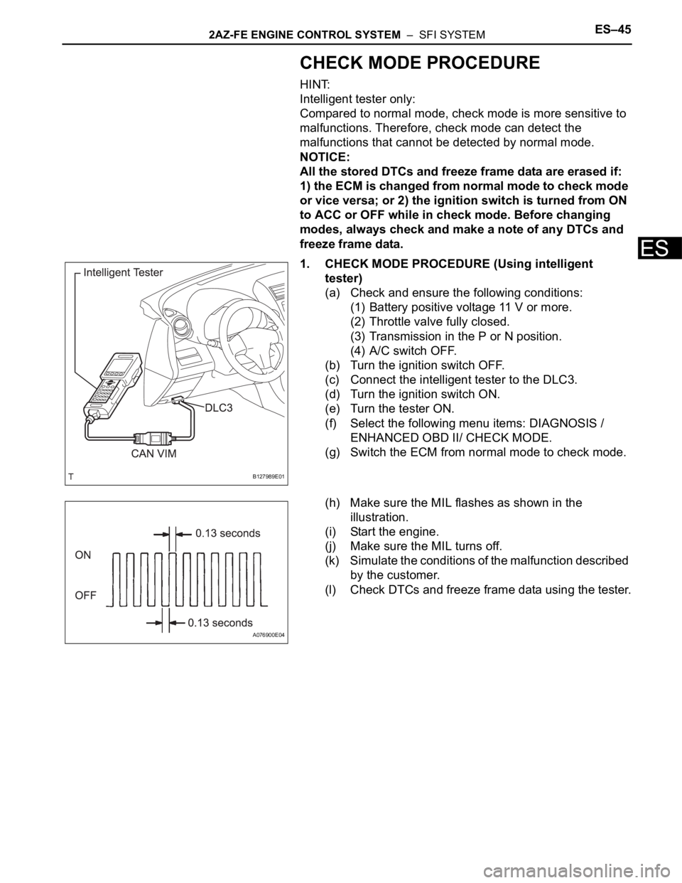
(c) Connect the intelligent tester to the DLC3.
(d) Turn the ignition switch ON.
(e) Turn the tester ON.
(f) Select the following menu items: DIAGNOSIS /
ENHANCED OBD II/ CHECK MODE.
(g) Switch the ECM from normal mode to check mode.
(h) Make sure the MIL flashes as shown in the
illustration.
(i) Start the engine.
(j) Make sure the MIL turns off.
(k) Simulate the conditions of the malfunction described
by the customer.
(l) Check DTCs and freeze frame data using the tester.
B127989E01
A076900E04
Page 1934 of 2000

ES–462AZ-FE ENGINE CONTROL SYSTEM – SFI SYSTEM
ES
FAIL-SAFE CHART
If any of the following DTCs are set, the ECM enters fail-safe
mode to allow the vehicle to be driven temporarily.
HINT:
*: The vehicle can be driven slowly when the accelerator
pedal is depressed firmly and slowly. If the accelerator pedal
is depressed quickly, the vehicle may speed up and slow
down erratically.
DTCs Components Fail-Safe OperationsFail-Safe Deactivation
Conditions
P0031 and P0032Air-Fuel Ratio (A/F) Sensor
HeaterECM turns off A/F sensor heater. Ignition switch OFF
P0037 and P0038Heated Oxygen (HO2) Sensor
HeaterECM turns off HO2 sensor heater. Ignition switch OFF
P0100, P0102 and P0103 Mass Air Flow (MAF) MeterECM calculates ignition timing
according to engine speed and
throttle valve position.Pass condition detected
P0110, P0112 and P0113Intake Air Temperature (IAT)
SensorECM estimates IAT to be 20
C
(68
F).Pass condition detected
P0115, P0117 and P0118Engine Coolant Temperature
(ECT) SensorECM estimates ECT to be 80
C
(176
F).Pass condition detected
P0120, P0121, P0122, P0123,
P0220, P0222, P0223, P0604,
P0606, P0607, P0657, P2102,
P2103, P2111, P2112, P2118,
P2119 and P2135Electronic Throttle Control
System (ETCS)ECM cuts off throttle actuator
current and throttle valve returned
to 6
throttle position by return
spring.
ECM then adjusts engine output
by controlling fuel injection
(intermittent fuel-cut) and ignition
timing in accordance with
accelerator pedal opening angle
to allow vehicle to continue at
minimal speed*.Pass condition detected and then
ignition switch turned OFF
P0327 and P0328 Knock SensorECM sets ignition timing to
maximum retard.Ignition switch OFF
P0351 to P0354 Igniter ECM cuts fuel. Pass condition detected
P1550, P1551, P1552 and P1602 Generator Alternator command is fixed. Pass condition detected
P2120, P2121, P2122, P2123,
P2125, P2127, P2128 and P2138Accelerator Pedal Position (APP)
SensorAPP sensor has 2 sensor circuits:
Main and Sub.
If either circuit malfunctions, ECM
controls engine using other
circuit.
If both circuits malfunction, ECM
regards accelerator pedal as
being released. As result, throttle
valve closed and engine idles.Pass condition detected and then
ignition switch turned OFF