2006 TOYOTA RAV4 ignition
[x] Cancel search: ignitionPage 1944 of 2000
ES–562AZ-FE ENGINE CONTROL SYSTEM – SFI SYSTEM
ES
HINT:
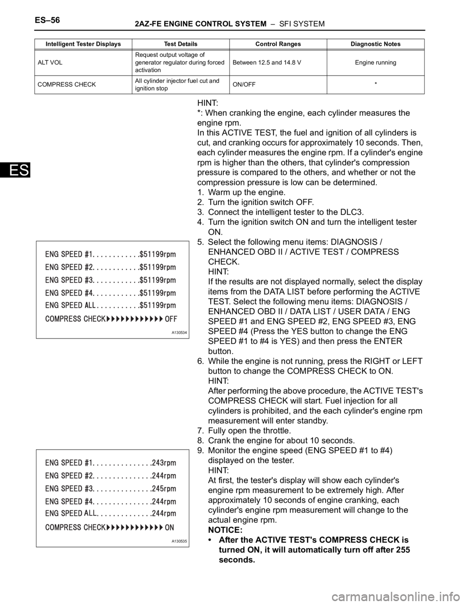
*: When cranking the engine, each cylinder measures the
engine rpm.
In this ACTIVE TEST, the fuel and ignition of all cylinders is
cut, and cranking occurs for approximately 10 seconds. Then,
each cylinder measures the engine rpm. If a cylinder's engine
rpm is higher than the others, that cylinder's compression
pressure is compared to the others, and whether or not the
compression pressure is low can be determined.
1. Warm up the engine.
2. Turn the ignition switch OFF.
3. Connect the intelligent tester to the DLC3.
4. Turn the ignition switch ON and turn the intelligent tester
ON.
5. Select the following menu items: DIAGNOSIS /
ENHANCED OBD II / ACTIVE TEST / COMPRESS
CHECK.
HINT:
If the results are not displayed normally, select the display
items from the DATA LIST before performing the ACTIVE
TEST. Select the following menu items: DIAGNOSIS /
ENHANCED OBD II / DATA LIST / USER DATA / ENG
SPEED #1 and ENG SPEED #2, ENG SPEED #3, ENG
SPEED #4 (Press the YES button to change the ENG
SPEED #1 to #4 is YES) and then press the ENTER
button.
6. While the engine is not running, press the RIGHT or LEFT
button to change the COMPRESS CHECK to ON.
HINT:
After performing the above procedure, the ACTIVE TEST's
COMPRESS CHECK will start. Fuel injection for all
cylinders is prohibited, and the each cylinder's engine rpm
measurement will enter standby.
7. Fully open the throttle.
8. Crank the engine for about 10 seconds.
9. Monitor the engine speed (ENG SPEED #1 to #4)
displayed on the tester.
HINT:
At first, the tester's display will show each cylinder's
engine rpm measurement to be extremely high. After
approximately 10 seconds of engine cranking, each
cylinder's engine rpm measurement will change to the
actual engine rpm.
NOTICE:
• After the ACTIVE TEST's COMPRESS CHECK is
turned ON, it will automatically turn off after 255
seconds.
ALT VOLRequest output voltage of
generator regulator during forced
activationBetween 12.5 and 14.8 V Engine running
COMPRESS CHECKAll cylinder injector fuel cut and
ignition stopON/OFF * Intelligent Tester Displays Test Details Control Ranges Diagnostic Notes
A130534
A130535
Page 1945 of 2000

2AZ-FE ENGINE CONTROL SYSTEM – SFI SYSTEMES–57
ES
• When the COMPRESS CHECK test is OFF and the
engine is cranked, the engine will start.
• If the COMPRESS CHECK test needs to be
performed after it is turned ON and performed once,
press EXIT to return to the ACTIVE TEST menu
screen. Then perform the COMPRESS CHECK test
again.
• Use a fully-charged battery.
3. SYSTEM CHECK
HINT:
Performing a SYSTEM CHECK enables the system,
which consists of multiple actuators, to be operated
without removing any parts. In addition, it can show
whether or not any DTCs are set, and can detect
potential malfunctions in the system. The SYSTEM
CHECK can be performed with the intelligent tester.
(a) Connect the intelligent tester to the DLC3.
(b) Turn the ignition switch ON.
(c) Turn the tester ON.
(d) Select the following menu items: DIAGNOSIS /
ENHANCED OBD II / SYSTEM CHECK.
(e) Perform the SYSTEM CHECK by referring to the
table below.
ECM:
Intelligent Tester Display Test DetailRecommended Fuel
Te m p e r a t u r eDiagnostic Note
EVAP SYS CHECK
(AUTO OPERATION)Perform 5 steps in order to
operate EVAP key-off monitor
automatically35
C (95F) or less• If no DTCs in PENDING
CODE after performing this
test, system functioning
normally
• Refer to EVAP system
EVAP SYS CHECK
(MANUAL OPERATION)Perform 5 steps in order to
operate EVAP key-off monitor
manually35
C (95F) or less• Used to detect malfunctioning
parts
• Refer to EVAP system
Page 1949 of 2000
2AZ-FE ENGINE CONTROL SYSTEM – SFI SYSTEMES–61
ES
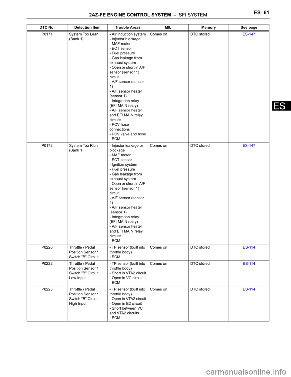
P0171 System Too Lean
(Bank 1)- Air induction system
- Injector blockage
- MAF meter
- ECT sensor
- Fuel pressure
- Gas leakage from
exhaust system
- Open or short in A/F
sensor (sensor 1)
circuit
- A/F sensor (sensor
1)
- A/F sensor heater
(sensor 1)
- Integration relay
(EFI MAIN relay)
- A/F sensor heater
and EFI MAIN relay
circuits
- PCV hose
connections
- PCV valve and hose
- ECMComes on DTC storedES-147
P0172 System Too Rich
(Bank 1)- Injector leakage or
blockage
- MAF meter
- ECT sensor
- Ignition system
- Fuel pressure
- Gas leakage from
exhaust system
- Open or short in A/F
sensor (sensor 1)
circuit
- A/F sensor (sensor
1)
- A/F sensor heater
(sensor 1)
- Integration relay
(EFI MAIN relay)
- A/F sensor heater
and EFI MAIN relay
circuits
- ECMComes on DTC storedES-147
P0220 Throttle / Pedal
Position Sensor /
Switch "B" Circuit- TP sensor (built into
throttle body)
- ECMComes on DTC storedES-114
P0222 Throttle / Pedal
Position Sensor /
Switch "B" Circuit
Low Input- TP sensor (built into
throttle body)
- Short in VTA2 circuit
- Open in VC circuit
- ECMComes on DTC storedES-114
P0223 Throttle / Pedal
Position Sensor /
Switch "B" Circuit
High Input- TP sensor (built into
throttle body)
- Open in VTA2 circuit
- Open in E2 circuit
- Short between VC
and VTA2 circuits
- ECMComes on DTC storedES-114 DTC No. Detection Item Trouble Areas MIL Memory See page
Page 1950 of 2000
ES–622AZ-FE ENGINE CONTROL SYSTEM – SFI SYSTEM
ES
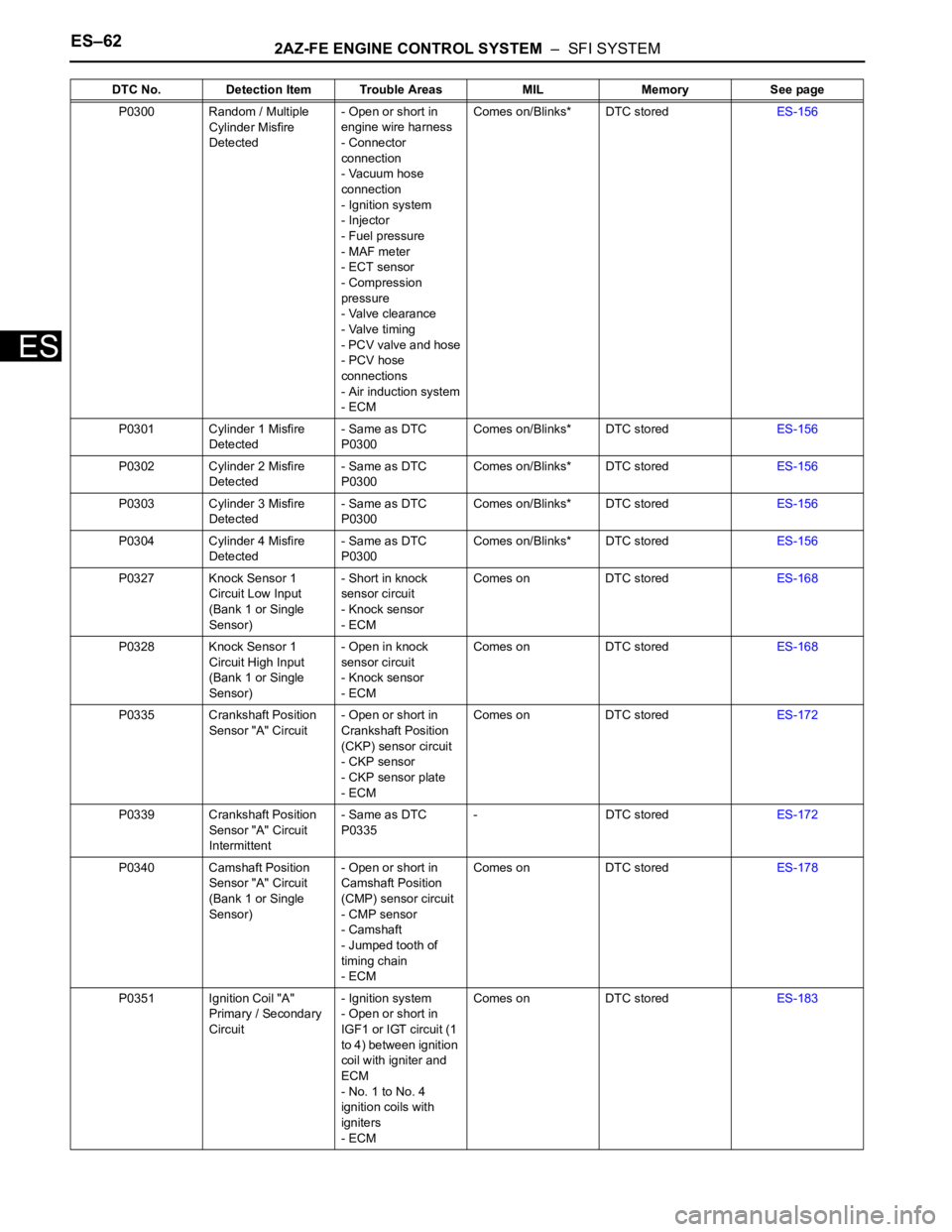
P0300 Random / Multiple
Cylinder Misfire
Detected- Open or short in
engine wire harness
- Connector
connection
- Vacuum hose
connection
- Ignition system
- Injector
- Fuel pressure
- MAF meter
- ECT sensor
- Compression
pressure
- Valve clearance
- Valve timing
- PCV valve and hose
- PCV hose
connections
- Air induction system
- ECMComes on/Blinks* DTC storedES-156
P0301 Cylinder 1 Misfire
Detected- Same as DTC
P0300Comes on/Blinks* DTC storedES-156
P0302 Cylinder 2 Misfire
Detected- Same as DTC
P0300Comes on/Blinks* DTC storedES-156
P0303 Cylinder 3 Misfire
Detected- Same as DTC
P0300Comes on/Blinks* DTC storedES-156
P0304 Cylinder 4 Misfire
Detected- Same as DTC
P0300Comes on/Blinks* DTC storedES-156
P0327 Knock Sensor 1
Circuit Low Input
(Bank 1 or Single
Sensor)- Short in knock
sensor circuit
- Knock sensor
- ECMComes on DTC storedES-168
P0328 Knock Sensor 1
Circuit High Input
(Bank 1 or Single
Sensor)- Open in knock
sensor circuit
- Knock sensor
- ECMComes on DTC storedES-168
P0335 Crankshaft Position
Sensor "A" Circuit- Open or short in
Crankshaft Position
(CKP) sensor circuit
- CKP sensor
- CKP sensor plate
- ECMComes on DTC storedES-172
P0339 Crankshaft Position
Sensor "A" Circuit
Intermittent- Same as DTC
P0335- DTC storedES-172
P0340 Camshaft Position
Sensor "A" Circuit
(Bank 1 or Single
Sensor)- Open or short in
Camshaft Position
(CMP) sensor circuit
- CMP sensor
- Camshaft
- Jumped tooth of
timing chain
- ECMComes on DTC storedES-178
P0351 Ignition Coil "A"
Primary / Secondary
Circuit- Ignition system
- Open or short in
IGF1 or IGT circuit (1
to 4) between ignition
coil with igniter and
ECM
- No. 1 to No. 4
ignition coils with
igniters
- ECMComes on DTC storedES-183 DTC No. Detection Item Trouble Areas MIL Memory See page
Page 1951 of 2000
2AZ-FE ENGINE CONTROL SYSTEM – SFI SYSTEMES–63
ES
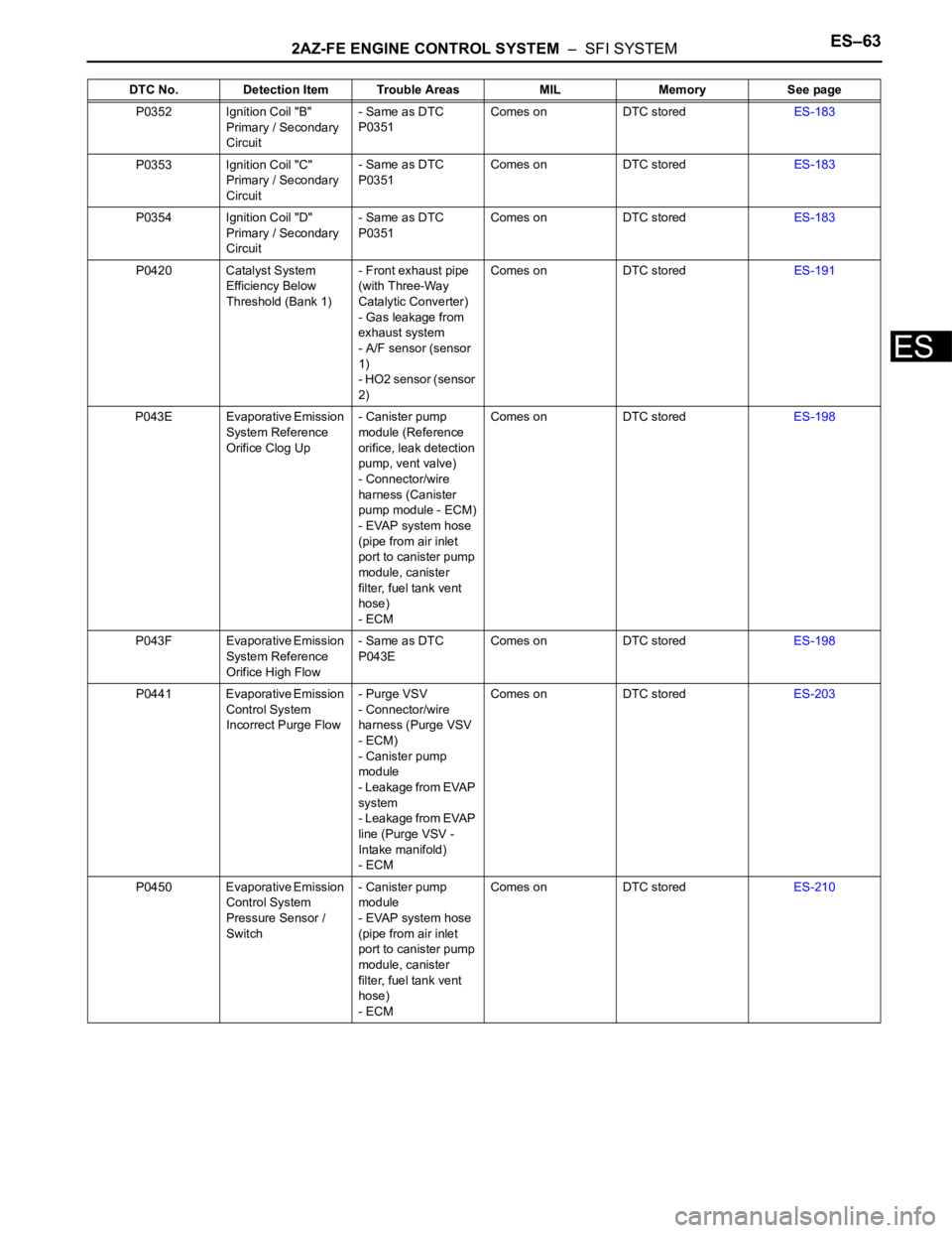
P0352 Ignition Coil "B"
Primary / Secondary
Circuit- Same as DTC
P0351Comes on DTC storedES-183
P0353 Ignition Coil "C"
Primary / Secondary
Circuit- Same as DTC
P0351Comes on DTC storedES-183
P0354 Ignition Coil "D"
Primary / Secondary
Circuit- Same as DTC
P0351Comes on DTC storedES-183
P0420 Catalyst System
Efficiency Below
Threshold (Bank 1)- Front exhaust pipe
(with Three-Way
Catalytic Converter)
- Gas leakage from
exhaust system
- A/F sensor (sensor
1)
- HO2 sensor (sensor
2)Comes on DTC storedES-191
P043E Evaporative Emission
System Reference
Orifice Clog Up- Canister pump
module (Reference
orifice, leak detection
pump, vent valve)
- Connector/wire
harness (Canister
pump module - ECM)
- EVAP system hose
(pipe from air inlet
port to canister pump
module, canister
filter, fuel tank vent
hose)
- ECMComes on DTC storedES-198
P043F Evaporative Emission
System Reference
Orifice High Flow- Same as DTC
P043EComes on DTC storedES-198
P0441 Evaporative Emission
Control System
Incorrect Purge Flow- Purge VSV
- Connector/wire
harness (Purge VSV
- ECM)
- Canister pump
module
- Leakage from EVAP
system
- Leakage from EVAP
line (Purge VSV -
Intake manifold)
- ECMComes on DTC storedES-203
P0450 Evaporative Emission
Control System
Pressure Sensor /
Switch- Canister pump
module
- EVAP system hose
(pipe from air inlet
port to canister pump
module, canister
filter, fuel tank vent
hose)
- ECMComes on DTC storedES-210 DTC No. Detection Item Trouble Areas MIL Memory See page
Page 1953 of 2000
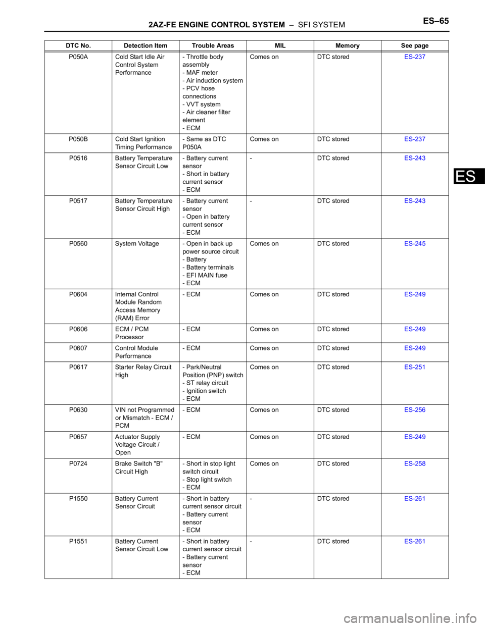
2AZ-FE ENGINE CONTROL SYSTEM – SFI SYSTEMES–65
ES
P050A Cold Start Idle Air
Control System
Performance- Throttle body
assembly
- MAF meter
- Air induction system
- PCV hose
connections
- VVT system
- Air cleaner filter
element
- ECMComes on DTC storedES-237
P050B Cold Start Ignition
Timing Performance- Same as DTC
P050AComes on DTC storedES-237
P0516 Battery Temperature
Sensor Circuit Low- Battery current
sensor
- Short in battery
current sensor
- ECM- DTC storedES-243
P0517 Battery Temperature
Sensor Circuit High- Battery current
sensor
- Open in battery
current sensor
- ECM- DTC storedES-243
P0560 System Voltage - Open in back up
power source circuit
- Battery
- Battery terminals
- EFI MAIN fuse
- ECMComes on DTC storedES-245
P0604 Internal Control
Module Random
Access Memory
(RAM) Error- ECM Comes on DTC storedES-249
P0606 ECM / PCM
Processor- ECM Comes on DTC storedES-249
P0607 Control Module
Performance- ECM Comes on DTC storedES-249
P0617 Starter Relay Circuit
High- Park/Neutral
Position (PNP) switch
- ST relay circuit
- Ignition switch
- ECMComes on DTC storedES-251
P0630 VIN not Programmed
or Mismatch - ECM /
PCM- ECM Comes on DTC storedES-256
P0657 Actuator Supply
Voltage Circuit /
Open- ECM Comes on DTC storedES-249
P0724 Brake Switch "B"
Circuit High- Short in stop light
switch circuit
- Stop light switch
- ECMComes on DTC storedES-258
P1550 Battery Current
Sensor Circuit- Short in battery
current sensor circuit
- Battery current
sensor
- ECM- DTC storedES-261
P1551 Battery Current
Sensor Circuit Low- Short in battery
current sensor circuit
- Battery current
sensor
- ECM- DTC storedES-261 DTC No. Detection Item Trouble Areas MIL Memory See page
Page 1958 of 2000

E S –702AZ-FE ENGINE CONTROL SYSTEM – SFI SYSTEM
ES
MONITOR DESCRIPTION
The ECM optimizes the valve timing using the VVT system to control the intake camshaft. The VVT
system includes the ECM, the OCV and the VVT controller. The ECM sends a target duty-cycle control
signal to the OCV. This control signal regulates the oil pressure supplied to the VVT controller. The VVT
controller can advance or retard the intake camshaft.
After the ECM sends the target duty-cycle control signal to the OCV, the ECM monitors the OCV current
to establish an actual duty-cycle. The ECM determines the existence of a malfunction and sets the DTC
when the actual duty-cycle ratio varies from the target duty-cycle ratio.
MONITOR STRATEGY
TYPICAL ENABLING CONDITIONS
TYPICAL MALFUNCTION THRESHOLDS
COMPONENT OPERATING RANGE
Related DTCs P0010: VVT OCV range check
Required Sensors/Components (Main) VVT OCV
Required Sensors/Components (Related) -
Frequency of Operation Continuous
Duration 1 second
MIL Operation Immediate
Sequence of Operation None
Monitor runs whenever following DTCs not present None
All of following conditions met -
Starter OFF
Ignition switch ON
Time after ignition switch OFF to ON 0.5 seconds or more
One of following conditions met -
A. All of following conditions met -
Battery voltage 11 to 13 V
Target duty ratio Less than 70 %
Output signal duty ratio 100 %
B. All of following conditions met -
Battery voltage 13 V or more
Target duty ratio Less than 80 %
Output signal duty ratio 100 %
C. Both of following conditions met -
Current cut status Not cut
Output signal duty ratio 3 % or less
VVT OCV duty ratio 3 to 100 %
Page 1963 of 2000

2AZ-FE ENGINE CONTROL SYSTEM – SFI SYSTEMES–75
ES
TYPICAL ENABLING CONDITIONS
TYPICAL MALFUNCTION THRESHOLDS
Advanced camshaft timing:
Retard camshaft timing:
If the difference between the target and actual camshaft timings is greater than the specified value, the
ECM operates the VVT actuator.
Then, the ECM monitors the camshaft timing change for 5 seconds.
WIRING DIAGRAM
Refer to DTC P0010 (see page ES-64).
INSPECTION PROCEDURE
NOTICE:
DTC P0011 or P0012 may be set when foreign objects in the engine oil are caught in some parts of
the system. The DTC will remain set even if the system returns to normal after a short time.
Foreign objects are filtered out by the oil filter.
HINT:
If DTC P0011 or P0012 is present, check the VVT (Variable Valve Timing) system.
Read freeze frame data using the intelligent tester. Freeze frame data records the engine condition when
malfunctions are detected. When troubleshooting, freeze frame data can help determine if the vehicle was
moving or stationary, if the engine was warmed up or not, if the air-fuel ratio was lean or rich, and other
data from the time the malfunction occurred.
(a) Connect the intelligent tester to the DLC3.
(b) Turn the ignition switch ON and turn the tester ON.
(c) Select the following menu items: DIAGNOSIS /
ENHANCED OBD II / DTC INFO / CURRENT CODES.
(d) Read DTCs.
Result
Monitor runs whenever following DTCs not presentP0100 - P0103 (MAF meter)
P0115 - P0118 (ECT sensor)
P0125 (Insufficient ECT for closed loop)
P0335 (CKP sensor)
P0340 (CMP sensor)
P0351 - P0354 (Igniter)
Battery voltage 11 V or more
Engine RPM 550 to 4,000 rpm
ECT 75
C (167F) to 100C (212F)
All of following conditions met -
Crank angle between reference position and actual intake camshaft
angle67
CA or more
Valve timing No change at advanced valve timing
All of following conditions met -
Crank angle between reference point and actual intake camshaft
angleLess than 67
CA
Valve timing No change at retarded valve timing
1CHECK ANY OTHER DTCS OUTPUT (IN ADDITION TO DTC P0011 OR P0012)
Display (DTC Output) Proceed To