Page 1964 of 2000
ES–762AZ-FE ENGINE CONTROL SYSTEM – SFI SYSTEM
ES
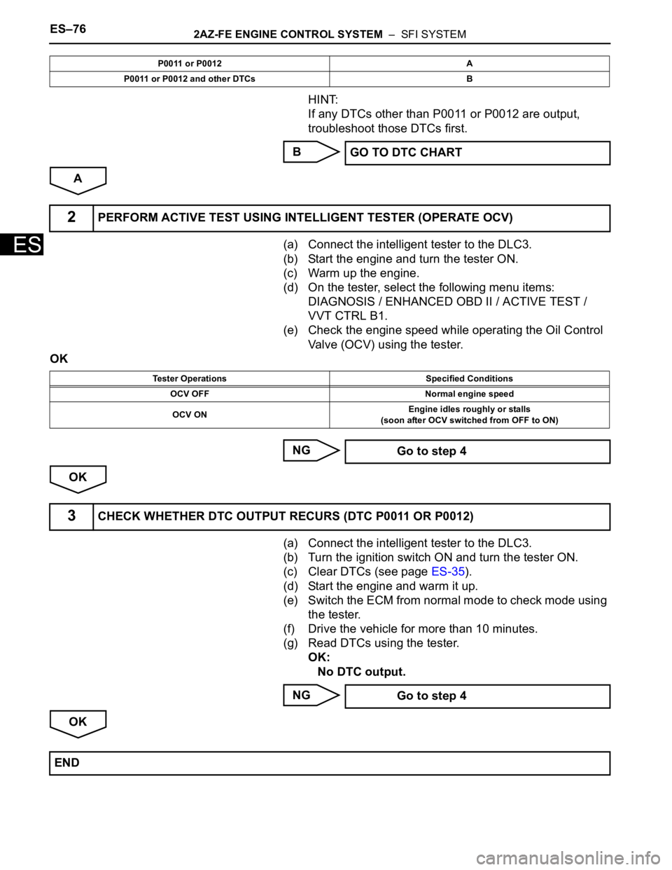
HINT:
If any DTCs other than P0011 or P0012 are output,
troubleshoot those DTCs first.
B
A
(a) Connect the intelligent tester to the DLC3.
(b) Start the engine and turn the tester ON.
(c) Warm up the engine.
(d) On the tester, select the following menu items:
DIAGNOSIS / ENHANCED OBD II / ACTIVE TEST /
VVT CTRL B1.
(e) Check the engine speed while operating the Oil Control
Valve (OCV) using the tester.
OK
NG
OK
(a) Connect the intelligent tester to the DLC3.
(b) Turn the ignition switch ON and turn the tester ON.
(c) Clear DTCs (see page ES-35).
(d) Start the engine and warm it up.
(e) Switch the ECM from normal mode to check mode using
the tester.
(f) Drive the vehicle for more than 10 minutes.
(g) Read DTCs using the tester.
OK:
No DTC output.
NG
OK
P0011 or P0012 A
P0011 or P0012 and other DTCs B
GO TO DTC CHART
2PERFORM ACTIVE TEST USING INTELLIGENT TESTER (OPERATE OCV)
Tester Operations Specified Conditions
OCV OFF Normal engine speed
OCV ONEngine idles roughly or stalls
(soon after OCV switched from OFF to ON)
Go to step 4
3CHECK WHETHER DTC OUTPUT RECURS (DTC P0011 OR P0012)
Go to step 4
END
Page 1966 of 2000
ES–782AZ-FE ENGINE CONTROL SYSTEM – SFI SYSTEM
ES
OK
NEXT
(a) Connect the intelligent tester to the DLC3.
(b) Turn the ignition switch ON and turn the tester ON.
(c) Clear DTCs (see page ES-35).
(d) Start the engine and warm it up.
(e) Switch the ECM from normal mode to check mode using
the tester.
(f) Drive the vehicle for more than 10 minutes.
(g) Read output DTCs using the tester.
Standard:
No DTC output.
HINT:
DTC P0011 or P0012 is output when foreign objects in
engine oil are caught in some parts of the system. These
codes will stay registered even if the system returns to
normal after a short time. These foreign objects are then
captured by the oil filter, thus eliminating the source of
the problem.
OK
NG
7REPLACE CAMSHAFT TIMING GEAR ASSEMBLY
8CHECK WHETHER DTC OUTPUT RECURS
SYSTEM OK
REPLACE ECM
Page 1968 of 2000
ES–802AZ-FE ENGINE CONTROL SYSTEM – SFI SYSTEM
ES
WIRING DIAGRAM
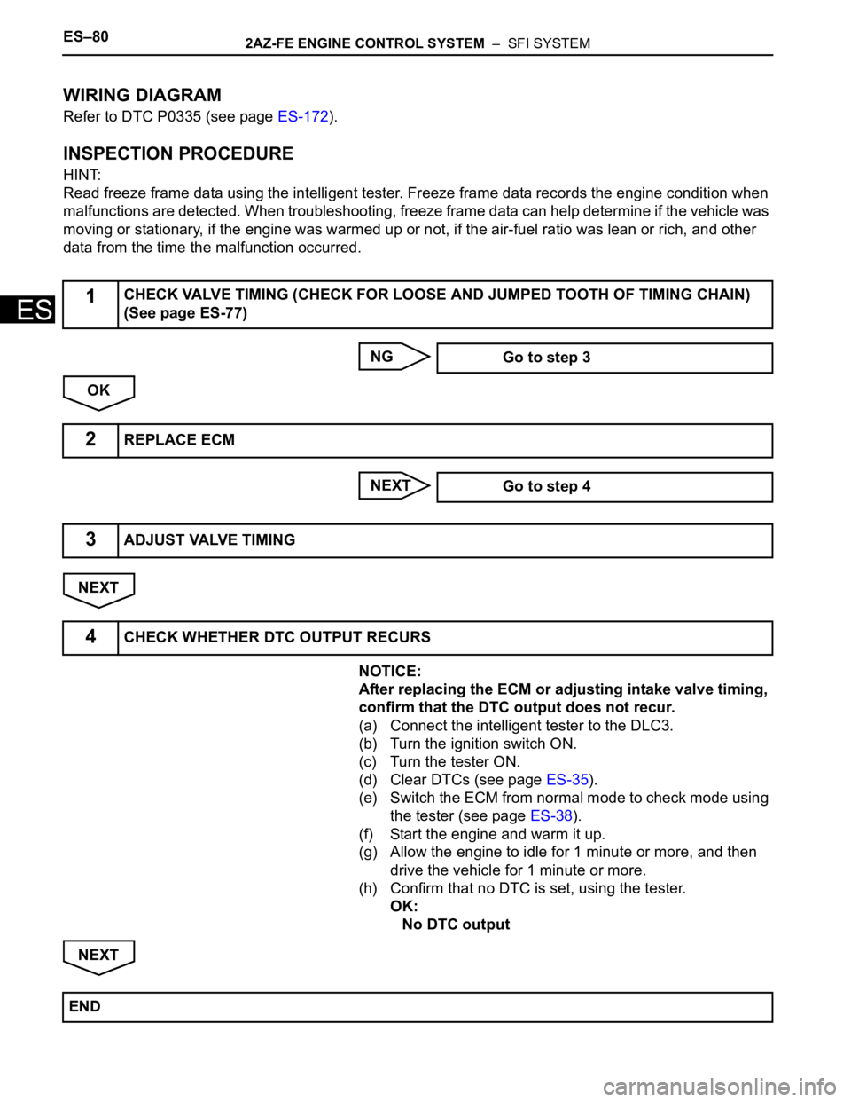
Refer to DTC P0335 (see page ES-172).
INSPECTION PROCEDURE
HINT:
Read freeze frame data using the intelligent tester. Freeze frame data records the engine condition when
malfunctions are detected. When troubleshooting, freeze frame data can help determine if the vehicle was
moving or stationary, if the engine was warmed up or not, if the air-fuel ratio was lean or rich, and other
data from the time the malfunction occurred.
NG
OK
NEXT
NEXT
NOTICE:
After replacing the ECM or adjusting intake valve timing,
confirm that the DTC output does not recur.
(a) Connect the intelligent tester to the DLC3.
(b) Turn the ignition switch ON.
(c) Turn the tester ON.
(d) Clear DTCs (see page ES-35).
(e) Switch the ECM from normal mode to check mode using
the tester (see page ES-38).
(f) Start the engine and warm it up.
(g) Allow the engine to idle for 1 minute or more, and then
drive the vehicle for 1 minute or more.
(h) Confirm that no DTC is set, using the tester.
OK:
No DTC output
NEXT
1CHECK VALVE TIMING (CHECK FOR LOOSE AND JUMPED TOOTH OF TIMING CHAIN)
(See page ES-77)
Go to step 3
2REPLACE ECM
Go to step 4
3ADJUST VALVE TIMING
4CHECK WHETHER DTC OUTPUT RECURS
END
Page 1969 of 2000
2AZ-FE ENGINE CONTROL SYSTEM – SFI SYSTEMES–81
ES
HINT:
• Although the DTC titles say oxygen sensor, these DTCs relate to the Air-Fuel Ratio (A/F) sensor.
• Sensor 1 refers to the sensor mounted in front of the Three-Way Catalytic Converter (TWC) and
located near the engine assembly.
DESCRIPTION
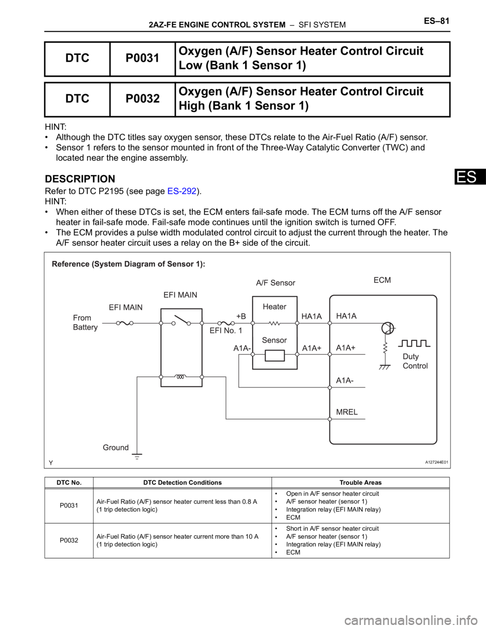
Refer to DTC P2195 (see page ES-292).
HINT:
• When either of these DTCs is set, the ECM enters fail-safe mode. The ECM turns off the A/F sensor
heater in fail-safe mode. Fail-safe mode continues until the ignition switch is turned OFF.
• The ECM provides a pulse width modulated control circuit to adjust the current through the heater. The
A/F sensor heater circuit uses a relay on the B+ side of the circuit.
DTC P0031Oxygen (A/F) Sensor Heater Control Circuit
Low (Bank 1 Sensor 1)
DTC P0032Oxygen (A/F) Sensor Heater Control Circuit
High (Bank 1 Sensor 1)
DTC No. DTC Detection Conditions Trouble Areas
P0031Air-Fuel Ratio (A/F) sensor heater current less than 0.8 A
(1 trip detection logic)• Open in A/F sensor heater circuit
• A/F sensor heater (sensor 1)
• Integration relay (EFI MAIN relay)
•ECM
P0032Air-Fuel Ratio (A/F) sensor heater current more than 10 A
(1 trip detection logic)• Short in A/F sensor heater circuit
• A/F sensor heater (sensor 1)
• Integration relay (EFI MAIN relay)
•ECM
A127244E01
Page 1971 of 2000
2AZ-FE ENGINE CONTROL SYSTEM – SFI SYSTEMES–83
ES
COMPONENT OPERATING RANGE
WIRING DIAGRAM
Refer to DTC P2195 (see page ES-296).
INSPECTION PROCEDURE
HINT:
Read freeze frame data using the intelligent tester. Freeze frame data records the engine condition when
malfunctions are detected. When troubleshooting, freeze frame data can help determine if the vehicle was
moving or stationary, if the engine was warmed up or not, if the air-fuel ratio was lean or rich, and other
data from the time the malfunction occurred.
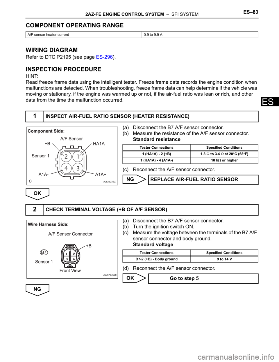
(a) Disconnect the B7 A/F sensor connector.
(b) Measure the resistance of the A/F sensor connector.
Standard resistance
(c) Reconnect the A/F sensor connector.
NG
OK
(a) Disconnect the B7 A/F sensor connector.
(b) Turn the ignition switch ON.
(c) Measure the voltage between the terminals of the B7 A/F
sensor connector and body ground.
Standard voltage
(d) Reconnect the A/F sensor connector.
OK
NG
A/F sensor heater current 0.9 to 9.9 A
1INSPECT AIR-FUEL RATIO SENSOR (HEATER RESISTANCE)
A052607E27
Tester Connections Specified Conditions
1 (HA1A) - 2 (+B) 1.8
to 3.4 at 20C (68F)
1 (HA1A) - 4 (A1A-) 10 k
or higher
REPLACE AIR-FUEL RATIO SENSOR
2CHECK TERMINAL VOLTAGE (+B OF A/F SENSOR)
A076787E08
Tester Connections Specified Conditions
B7-2 (+B) - Body ground 9 to 14 V
Go to step 5
Page 1974 of 2000
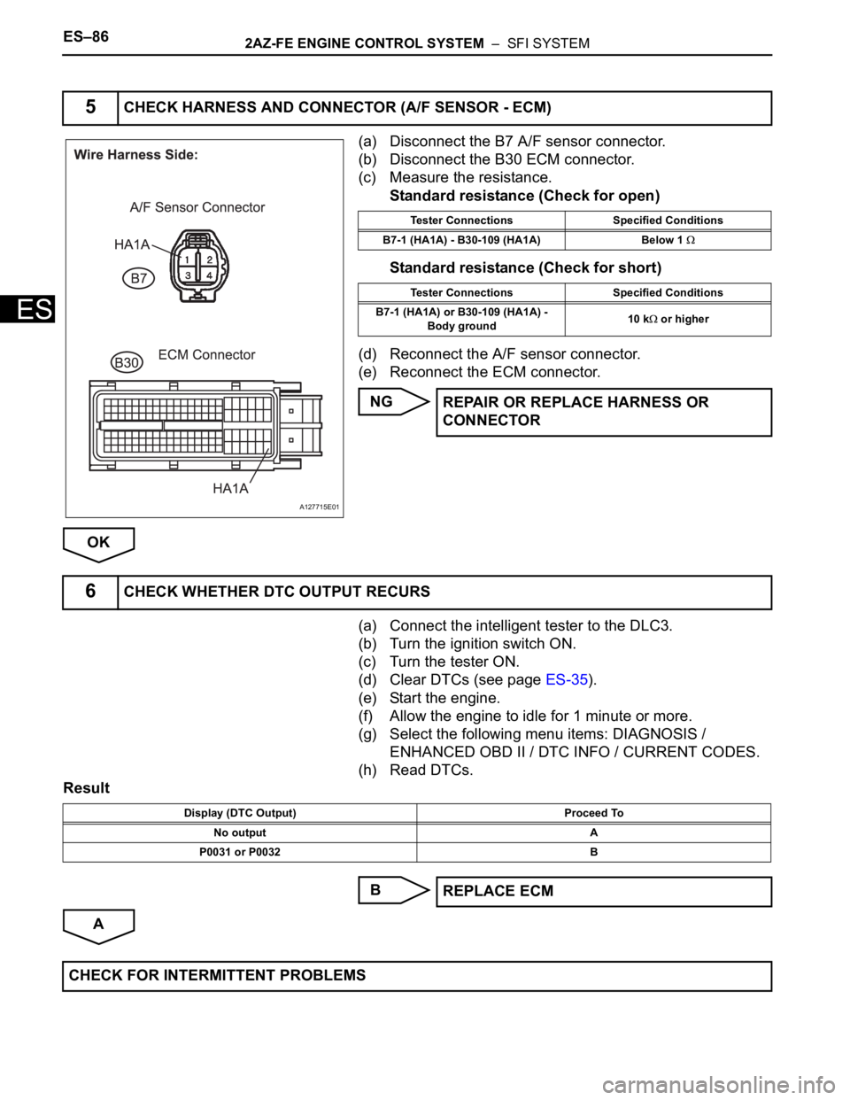
ES–862AZ-FE ENGINE CONTROL SYSTEM – SFI SYSTEM
ES
(a) Disconnect the B7 A/F sensor connector.
(b) Disconnect the B30 ECM connector.
(c) Measure the resistance.
Standard resistance (Check for open)
Standard resistance (Check for short)
(d) Reconnect the A/F sensor connector.
(e) Reconnect the ECM connector.
NG
OK
(a) Connect the intelligent tester to the DLC3.
(b) Turn the ignition switch ON.
(c) Turn the tester ON.
(d) Clear DTCs (see page ES-35).
(e) Start the engine.
(f) Allow the engine to idle for 1 minute or more.
(g) Select the following menu items: DIAGNOSIS /
ENHANCED OBD II / DTC INFO / CURRENT CODES.
(h) Read DTCs.
Result
B
A
5CHECK HARNESS AND CONNECTOR (A/F SENSOR - ECM)
A127715E01
Tester Connections Specified Conditions
B7-1 (HA1A) - B30-109 (HA1A) Below 1
Tester Connections Specified Conditions
B7-1 (HA1A) or B30-109 (HA1A) -
Body ground10 k
or higher
REPAIR OR REPLACE HARNESS OR
CONNECTOR
6CHECK WHETHER DTC OUTPUT RECURS
Display (DTC Output) Proceed To
No output A
P0031 or P0032 B
REPLACE ECM
CHECK FOR INTERMITTENT PROBLEMS
Page 1975 of 2000
2AZ-FE ENGINE CONTROL SYSTEM – SFI SYSTEMES–87
ES
DESCRIPTION
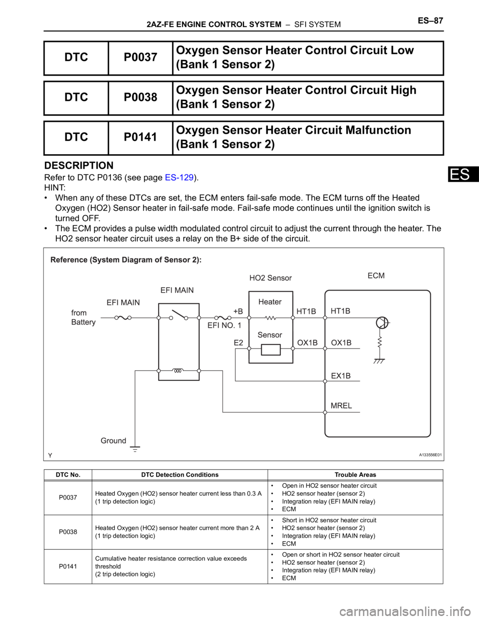
Refer to DTC P0136 (see page ES-129).
HINT:
• When any of these DTCs are set, the ECM enters fail-safe mode. The ECM turns off the Heated
Oxygen (HO2) Sensor heater in fail-safe mode. Fail-safe mode continues until the ignition switch is
turned OFF.
• The ECM provides a pulse width modulated control circuit to adjust the current through the heater. The
HO2 sensor heater circuit uses a relay on the B+ side of the circuit.
DTC P0037Oxygen Sensor Heater Control Circuit Low
(Bank 1 Sensor 2)
DTC P0038Oxygen Sensor Heater Control Circuit High
(Bank 1 Sensor 2)
DTC P0141Oxygen Sensor Heater Circuit Malfunction
(Bank 1 Sensor 2)
DTC No. DTC Detection Conditions Trouble Areas
P0037Heated Oxygen (HO2) sensor heater current less than 0.3 A
(1 trip detection logic)• Open in HO2 sensor heater circuit
• HO2 sensor heater (sensor 2)
• Integration relay (EFI MAIN relay)
•ECM
P0038Heated Oxygen (HO2) sensor heater current more than 2 A
(1 trip detection logic)• Short in HO2 sensor heater circuit
• HO2 sensor heater (sensor 2)
• Integration relay (EFI MAIN relay)
•ECM
P0141Cumulative heater resistance correction value exceeds
threshold
(2 trip detection logic)• Open or short in HO2 sensor heater circuit
• HO2 sensor heater (sensor 2)
• Integration relay (EFI MAIN relay)
•ECM
A133556E01
Page 1978 of 2000
ES–902AZ-FE ENGINE CONTROL SYSTEM – SFI SYSTEM
ES
(a) Disconnect the B19 HO2 sensor connector.
(b) Turn the ignition switch ON.
(c) Measure the voltage between the terminals of the B19
HO2 sensor connector and body ground.
Standard voltage
(d) Reconnect the HO2 sensor connector.
OK
NG
NG
OK
2CHECK TERMINAL VOLTAGE (+B OF HO2 SENSOR)
A072895E07
Tester Connections Specified Conditions
B19-2 (+B) - Body ground 9 to 14 V
Go to step 5
3INSPECT INTEGRATION RELAY (EFI MAIN RELAY) (See page ES-84)
REPLACE INTEGRATION RELAY