Page 564 of 2000
ES–402GR-FE ENGINE CONTROL SYSTEM – SFI SYSTEM
ES
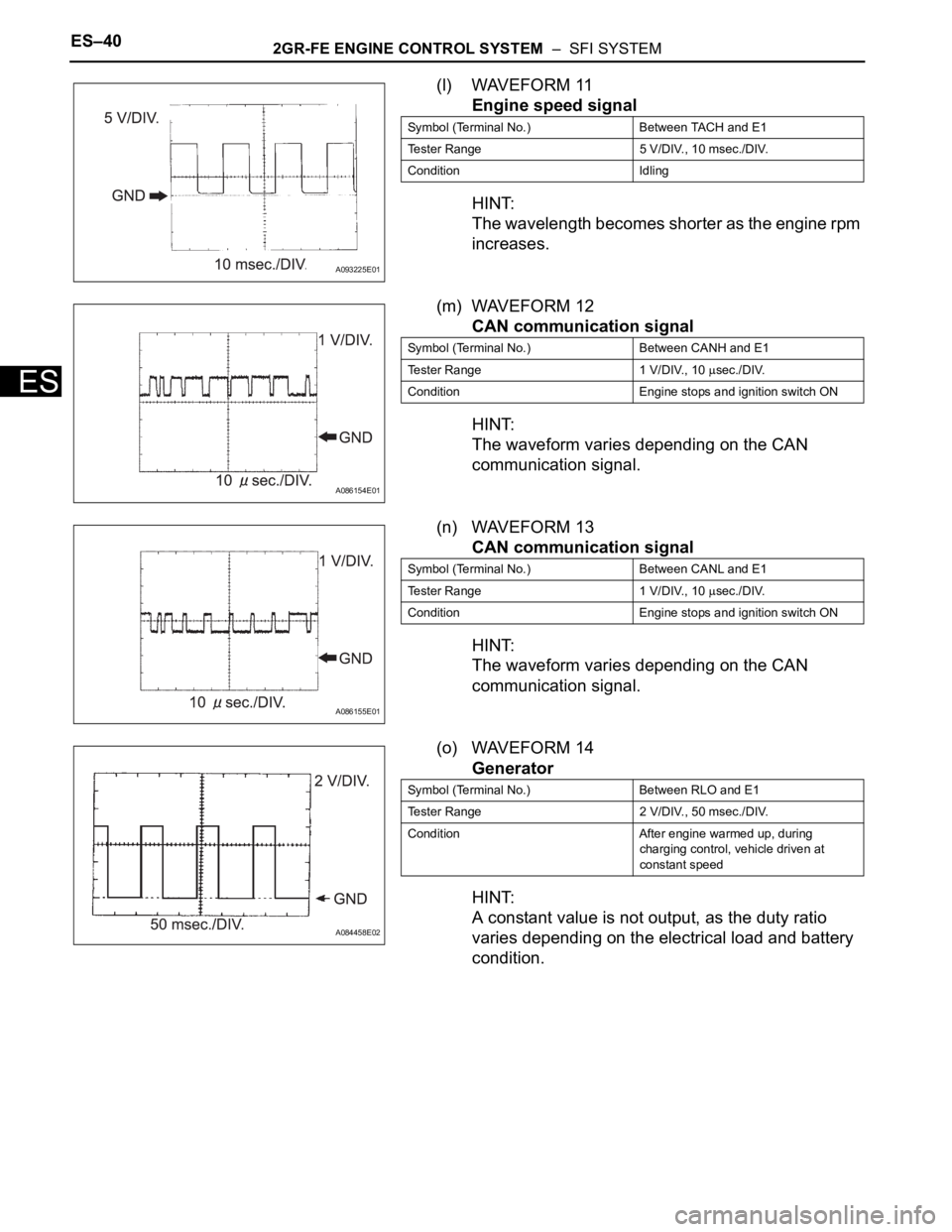
(l) WAVEFORM 11
Engine speed signal
HINT:
The wavelength becomes shorter as the engine rpm
increases.
(m) WAVEFORM 12
CAN communication signal
HINT:
The waveform varies depending on the CAN
communication signal.
(n) WAVEFORM 13
CAN communication signal
HINT:
The waveform varies depending on the CAN
communication signal.
(o) WAVEFORM 14
Generator
HINT:
A constant value is not output, as the duty ratio
varies depending on the electrical load and battery
condition.
A093225E01
Symbol (Terminal No.) Between TACH and E1
Tester Range 5 V/DIV., 10 msec./DIV.
Condition Idling
A086154E01
Symbol (Terminal No.) Between CANH and E1
Tester Range 1 V/DIV., 10
sec./DIV.
Condition Engine stops and ignition switch ON
A086155E01
Symbol (Terminal No.) Between CANL and E1
Tester Range 1 V/DIV., 10
sec./DIV.
Condition Engine stops and ignition switch ON
A084458E02
Symbol (Terminal No.) Between RLO and E1
Tester Range 2 V/DIV., 50 msec./DIV.
Condition After engine warmed up, during
charging control, vehicle driven at
constant speed
Page 565 of 2000
2GR-FE ENGINE CONTROL SYSTEM – SFI SYSTEMES–41
ES
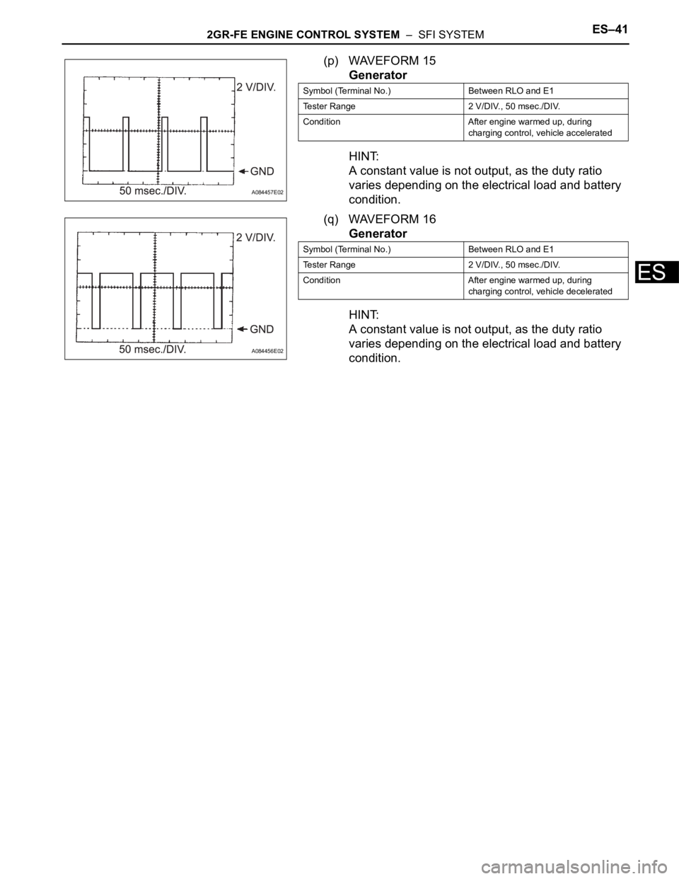
(p) WAVEFORM 15
Generator
HINT:
A constant value is not output, as the duty ratio
varies depending on the electrical load and battery
condition.
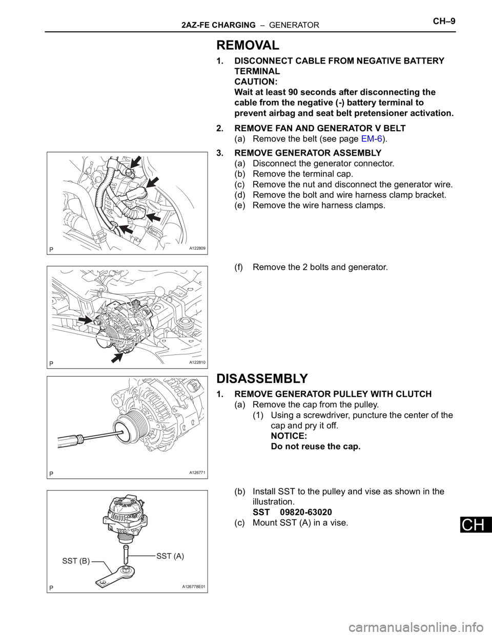
(q) WAVEFORM 16
Generator
HINT:
A constant value is not output, as the duty ratio
varies depending on the electrical load and battery
condition.
A084457E02
Symbol (Terminal No.) Between RLO and E1
Tester Range 2 V/DIV., 50 msec./DIV.
Condition After engine warmed up, during
charging control, vehicle accelerated
A084456E02
Symbol (Terminal No.) Between RLO and E1
Tester Range 2 V/DIV., 50 msec./DIV.
Condition After engine warmed up, during
charging control, vehicle decelerated
Page 920 of 2000
2AZ-FE CHARGING – GENERATORCH–9
CH
REMOVAL
1. DISCONNECT CABLE FROM NEGATIVE BATTERY
TERMINAL
CAUTION:
Wait at least 90 seconds after disconnecting the
cable from the negative (-) battery terminal to
prevent airbag and seat belt pretensioner activation.
2. REMOVE FAN AND GENERATOR V BELT
(a) Remove the belt (see page EM-6).
3. REMOVE GENERATOR ASSEMBLY
(a) Disconnect the generator connector.
(b) Remove the terminal cap.
(c) Remove the nut and disconnect the generator wire.
(d) Remove the bolt and wire harness clamp bracket.
(e) Remove the wire harness clamps.
(f) Remove the 2 bolts and generator.
DISASSEMBLY
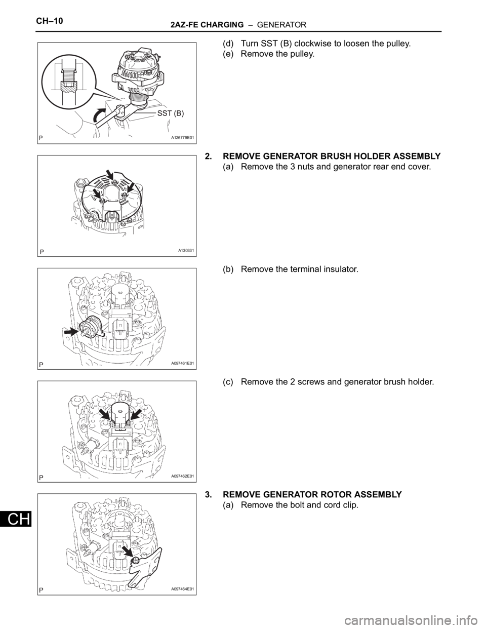
1. REMOVE GENERATOR PULLEY WITH CLUTCH
(a) Remove the cap from the pulley.
(1) Using a screwdriver, puncture the center of the
cap and pry it off.
NOTICE:
Do not reuse the cap.
(b) Install SST to the pulley and vise as shown in the
illustration.
SST 09820-63020
(c) Mount SST (A) in a vise.
A122809
A122810
A126771
A126778E01
Page 921 of 2000
CH–102AZ-FE CHARGING – GENERATOR
CH
(d) Turn SST (B) clockwise to loosen the pulley.
(e) Remove the pulley.
2. REMOVE GENERATOR BRUSH HOLDER ASSEMBLY
(a) Remove the 3 nuts and generator rear end cover.
(b) Remove the terminal insulator.
(c) Remove the 2 screws and generator brush holder.
3. REMOVE GENERATOR ROTOR ASSEMBLY
(a) Remove the bolt and cord clip.
A126779E01
A130331
A097461E01
A097462E01
A097464E01
Page 922 of 2000
2AZ-FE CHARGING – GENERATORCH–11
CH
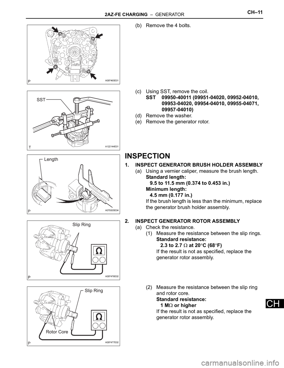
(b) Remove the 4 bolts.
(c) Using SST, remove the coil.
SST 09950-40011 (09951-04020, 09952-04010,
09953-04020, 09954-04010, 09955-04071,
09957-04010)
(d) Remove the washer.
(e) Remove the generator rotor.
INSPECTION
1. INSPECT GENERATOR BRUSH HOLDER ASSEMBLY
(a) Using a vernier caliper, measure the brush length.
Standard length:
9.5 to 11.5 mm (0.374 to 0.453 in.)
Minimum length:
4.5 mm (0.177 in.)
If the brush length is less than the minimum, replace
the generator brush holder assembly.
2. INSPECT GENERATOR ROTOR ASSEMBLY
(a) Check the resistance.
(1) Measure the resistance between the slip rings.
Standard resistance:
2.3 to 2.7
at 20C (68F)
If the result is not as specified, replace the
generator rotor assembly.
(2) Measure the resistance between the slip ring
and rotor core.
Standard resistance:
1 M
or higher
If the result is not as specified, replace the
generator rotor assembly.
A097465E01
A122144E01
A079305E04
A097476E02
A097477E02
Page 923 of 2000
CH–122AZ-FE CHARGING – GENERATOR
CH
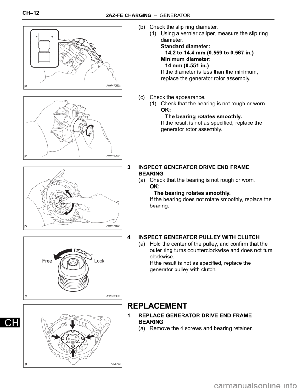
(b) Check the slip ring diameter.
(1) Using a vernier caliper, measure the slip ring
diameter.
Standard diameter:
14.2 to 14.4 mm (0.559 to 0.567 in.)
Minimum diameter:
14 mm (0.551 in.)
If the diameter is less than the minimum,
replace the generator rotor assembly.
(c) Check the appearance.
(1) Check that the bearing is not rough or worn.
OK:
The bearing rotates smoothly.
If the result is not as specified, replace the
generator rotor assembly.
3. INSPECT GENERATOR DRIVE END FRAME
BEARING
(a) Check that the bearing is not rough or worn.
OK:
The bearing rotates smoothly.
If the bearing does not rotate smoothly, replace the
bearing.
4. INSPECT GENERATOR PULLEY WITH CLUTCH
(a) Hold the center of the pulley, and confirm that the
outer ring turns counterclockwise and does not turn
clockwise.
If the result is not as specified, replace the
generator pulley with clutch.
REPLACEMENT
1. REPLACE GENERATOR DRIVE END FRAME
BEARING
(a) Remove the 4 screws and bearing retainer.
A097470E02
A097469E01
A097471E01
A126783E01
A126772
Page 924 of 2000
2AZ-FE CHARGING – GENERATORCH–13
CH
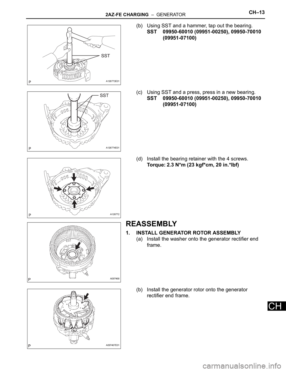
(b) Using SST and a hammer, tap out the bearing.
SST 09950-60010 (09951-00250), 09950-70010
(09951-07100)
(c) Using SST and a press, press in a new bearing.
SST 09950-60010 (09951-00250), 09950-70010
(09951-07100)
(d) Install the bearing retainer with the 4 screws.
Torque: 2.3 N*m (23 kgf*cm, 20 in.*lbf)
REASSEMBLY
1. INSTALL GENERATOR ROTOR ASSEMBLY
(a) Install the washer onto the generator rectifier end
frame.
(b) Install the generator rotor onto the generator
rectifier end frame.
A126773E01
A126774E01
A126772
A097468
A097467E01
Page 925 of 2000
CH–142AZ-FE CHARGING – GENERATOR
CH
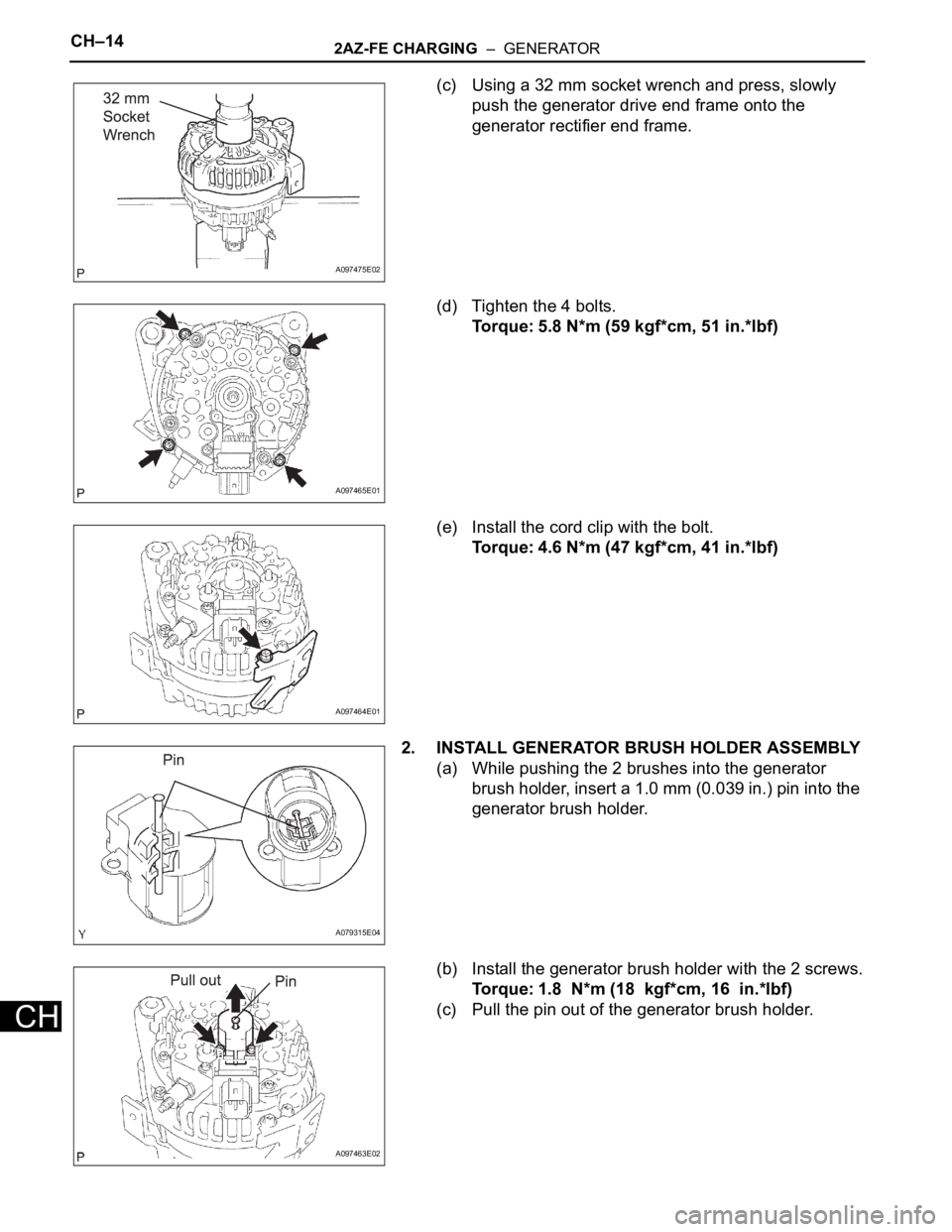
(c) Using a 32 mm socket wrench and press, slowly
push the generator drive end frame onto the
generator rectifier end frame.
(d) Tighten the 4 bolts.
Torque: 5.8 N*m (59 kgf*cm, 51 in.*lbf)
(e) Install the cord clip with the bolt.
Torque: 4.6 N*m (47 kgf*cm, 41 in.*lbf)
2. INSTALL GENERATOR BRUSH HOLDER ASSEMBLY
(a) While pushing the 2 brushes into the generator
brush holder, insert a 1.0 mm (0.039 in.) pin into the
generator brush holder.
(b) Install the generator brush holder with the 2 screws.
Torque: 1.8 N*m (18 kgf*cm, 16 in.*lbf)
(c) Pull the pin out of the generator brush holder.
A097475E02
A097465E01
A097464E01
A079315E04
A097463E02