Page 934 of 2000
2GR-FE CHARGING – GENERATORCH–15
CH
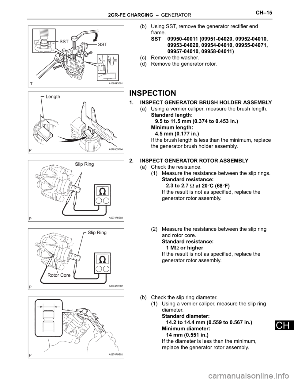
(b) Using SST, remove the generator rectifier end
frame.
SST 09950-40011 (09951-04020, 09952-04010,
09953-04020, 09954-04010, 09955-04071,
09957-04010, 09958-04011)
(c) Remove the washer.
(d) Remove the generator rotor.
INSPECTION
1. INSPECT GENERATOR BRUSH HOLDER ASSEMBLY
(a) Using a vernier caliper, measure the brush length.
Standard length:
9.5 to 11.5 mm (0.374 to 0.453 in.)
Minimum length:
4.5 mm (0.177 in.)
If the brush length is less than the minimum, replace
the generator brush holder assembly.
2. INSPECT GENERATOR ROTOR ASSEMBLY
(a) Check the resistance.
(1) Measure the resistance between the slip rings.
Standard resistance:
2.3 to 2.7
at 20C (68F)
If the result is not as specified, replace the
generator rotor assembly.
(2) Measure the resistance between the slip ring
and rotor core.
Standard resistance:
1 M
or higher
If the result is not as specified, replace the
generator rotor assembly.
(b) Check the slip ring diameter.
(1) Using a vernier caliper, measure the slip ring
diameter.
Standard diameter:
14.2 to 14.4 mm (0.559 to 0.567 in.)
Minimum diameter:
14 mm (0.551 in.)
If the diameter is less than the minimum,
replace the generator rotor assembly.
A136843E01
A079305E04
A097476E02
A097477E02
A097470E02
Page 935 of 2000
CH–162GR-FE CHARGING – GENERATOR
CH
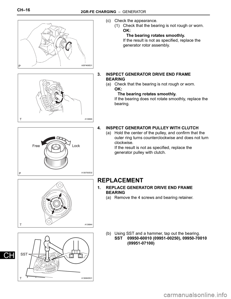
(c) Check the appearance.
(1) Check that the bearing is not rough or worn.
OK:
The bearing rotates smoothly.
If the result is not as specified, replace the
generator rotor assembly.
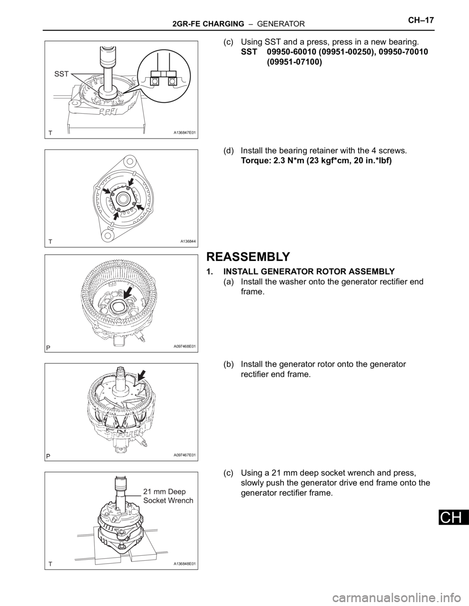
3. INSPECT GENERATOR DRIVE END FRAME
BEARING
(a) Check that the bearing is not rough or worn.
OK:
The bearing rotates smoothly.
If the bearing does not rotate smoothly, replace the
bearing.
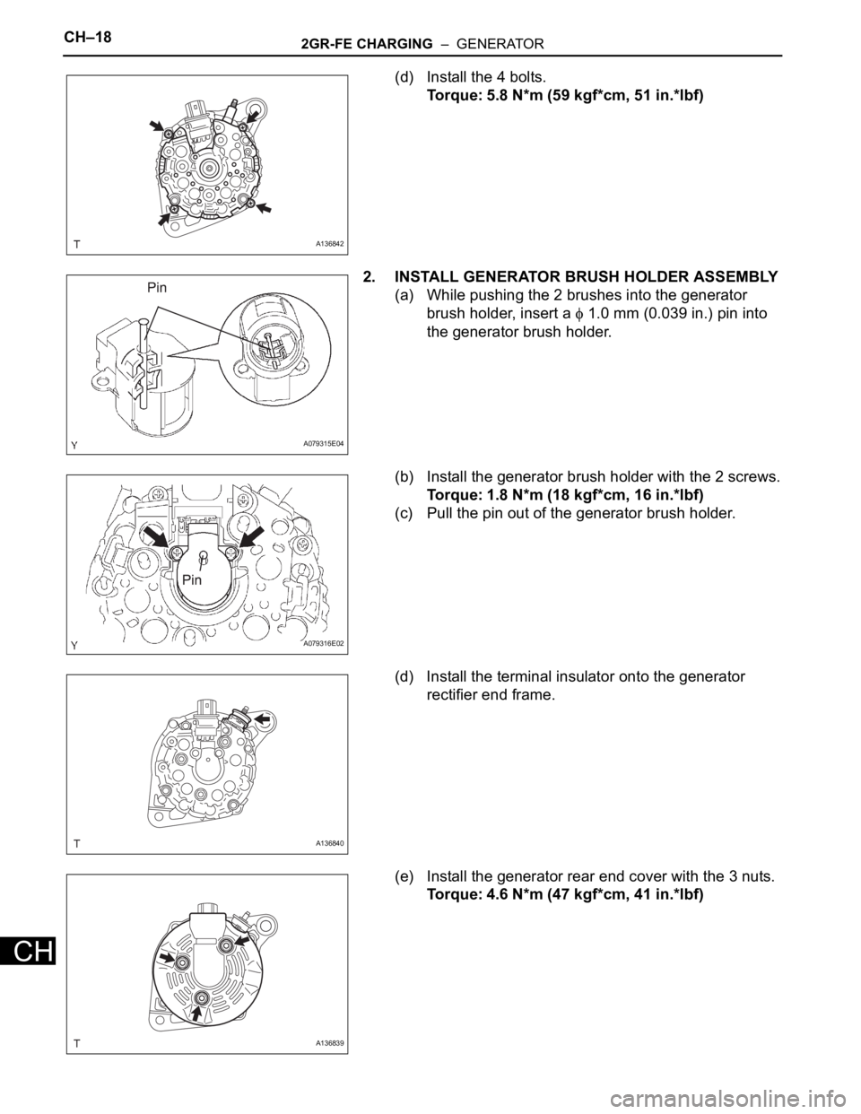
4. INSPECT GENERATOR PULLEY WITH CLUTCH
(a) Hold the center of the pulley, and confirm that the
outer ring turns counterclockwise and does not turn
clockwise.
If the result is not as specified, replace the
generator pulley with clutch.
REPLACEMENT
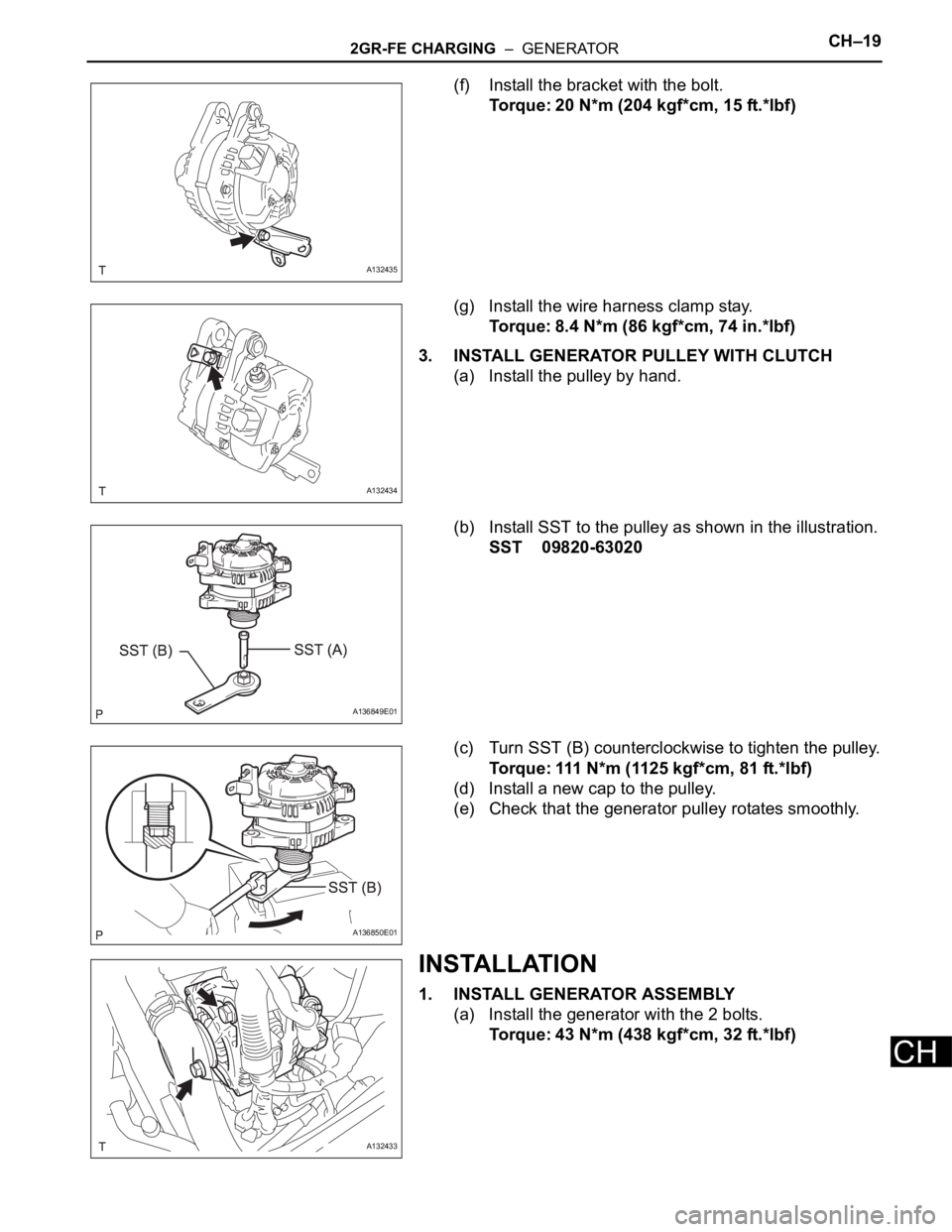
1. REPLACE GENERATOR DRIVE END FRAME
BEARING
(a) Remove the 4 screws and bearing retainer.
(b) Using SST and a hammer, tap out the bearing.
SST 09950-60010 (09951-00250), 09950-70010
(09951-07100)
A097469E01
A136846
A126783E02
A136844
A136845E01
Page 936 of 2000
2GR-FE CHARGING – GENERATORCH–17
CH
(c) Using SST and a press, press in a new bearing.
SST 09950-60010 (09951-00250), 09950-70010
(09951-07100)
(d) Install the bearing retainer with the 4 screws.
Torque: 2.3 N*m (23 kgf*cm, 20 in.*lbf)
REASSEMBLY
1. INSTALL GENERATOR ROTOR ASSEMBLY
(a) Install the washer onto the generator rectifier end
frame.
(b) Install the generator rotor onto the generator
rectifier end frame.
(c) Using a 21 mm deep socket wrench and press,
slowly push the generator drive end frame onto the
generator rectifier frame.
A136847E01
A136844
A097468E01
A097467E01
A136848E01
Page 937 of 2000
CH–182GR-FE CHARGING – GENERATOR
CH
(d) Install the 4 bolts.
Torque: 5.8 N*m (59 kgf*cm, 51 in.*lbf)
2. INSTALL GENERATOR BRUSH HOLDER ASSEMBLY
(a) While pushing the 2 brushes into the generator
brush holder, insert a
1.0 mm (0.039 in.) pin into
the generator brush holder.
(b) Install the generator brush holder with the 2 screws.
Torque: 1.8 N*m (18 kgf*cm, 16 in.*lbf)
(c) Pull the pin out of the generator brush holder.
(d) Install the terminal insulator onto the generator
rectifier end frame.
(e) Install the generator rear end cover with the 3 nuts.
Torque: 4.6 N*m (47 kgf*cm, 41 in.*lbf)
A136842
A079315E04
A079316E02
A136840
A136839
Page 938 of 2000
2GR-FE CHARGING – GENERATORCH–19
CH
(f) Install the bracket with the bolt.
Torque: 20 N*m (204 kgf*cm, 15 ft.*lbf)
(g) Install the wire harness clamp stay.
Torque: 8.4 N*m (86 kgf*cm, 74 in.*lbf)
3. INSTALL GENERATOR PULLEY WITH CLUTCH
(a) Install the pulley by hand.
(b) Install SST to the pulley as shown in the illustration.
SST 09820-63020
(c) Turn SST (B) counterclockwise to tighten the pulley.
Torque: 111 N*m (1125 kgf*cm, 81 ft.*lbf)
(d) Install a new cap to the pulley.
(e) Check that the generator pulley rotates smoothly.
INSTALLATION
1. INSTALL GENERATOR ASSEMBLY
(a) Install the generator with the 2 bolts.
Torque: 43 N*m (438 kgf*cm, 32 ft.*lbf)
A132435
A132434
A136849E01
A136850E01
A132433
Page 939 of 2000
CH–202GR-FE CHARGING – GENERATOR
CH
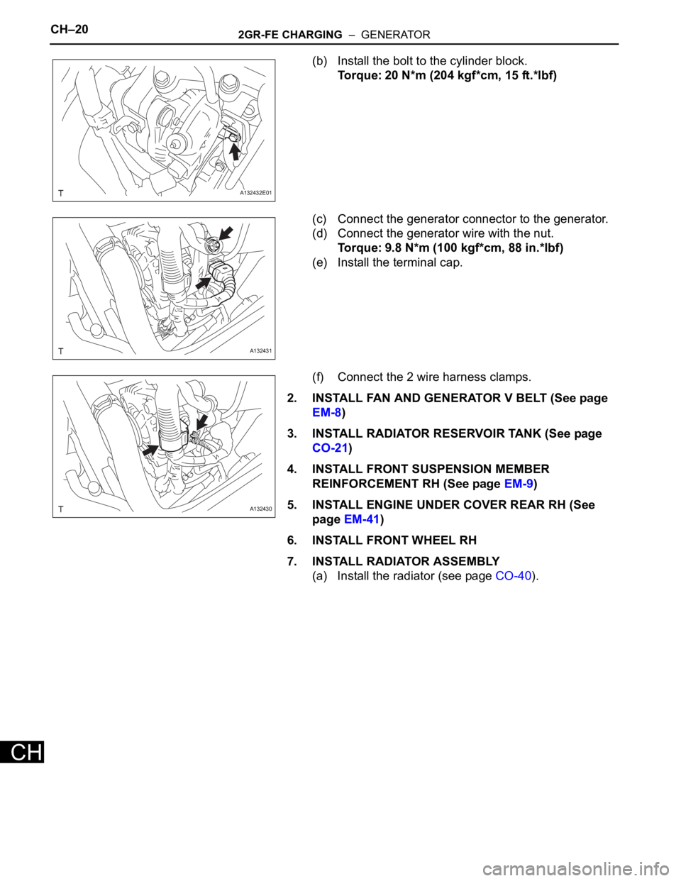
(b) Install the bolt to the cylinder block.
Torque: 20 N*m (204 kgf*cm, 15 ft.*lbf)
(c) Connect the generator connector to the generator.
(d) Connect the generator wire with the nut.
Torque: 9.8 N*m (100 kgf*cm, 88 in.*lbf)
(e) Install the terminal cap.
(f) Connect the 2 wire harness clamps.
2. INSTALL FAN AND GENERATOR V BELT (See page
EM-8)
3. INSTALL RADIATOR RESERVOIR TANK (See page
CO-21)
4. INSTALL FRONT SUSPENSION MEMBER
REINFORCEMENT RH (See page EM-9)
5. INSTALL ENGINE UNDER COVER REAR RH (See
page EM-41)
6. INSTALL FRONT WHEEL RH
7. INSTALL RADIATOR ASSEMBLY
(a) Install the radiator (see page CO-40).
A132432E01
A132431
A132430
Page 1939 of 2000

2AZ-FE ENGINE CONTROL SYSTEM – SFI SYSTEMES–51
ES
CAT TEMP B1S2Estimated catalyst temperature
(sensor 2):
Min.: -40C, Max.: 6,513.5C--
S O2S B1S2Sub heated oxygen sensor
impedance (sensor2):
Min.: 0
, Max.: 21247.68
--
INI COOL TEMPEngine coolant temperature at
engine start:
Min.: -40
C, Max.: 120CClose to ambient air
temperature-
INI INTAKE TEMPIntake air temperature at engine
start:
Min.: -40
C, Max.: 120CClose to ambient air
temperature-
INJ VOLInjection volume (Cylinder 1):
Min.: 0 ml, Max.: 2.048 ml0 to 0.15 ml: IdlingQuantity of fuel injection volume
for 10 times
STARTER SIGStarter switch (STSW) signal:
ON or OFFON: Cranking -
PS SWPower steering signal:
ON or OFFON: Power steering operation -
PS SIGNALPower steering signal (history):
ON or OFFON: When steering wheel first
turned after battery terminals
connectedSignal status usually ON until
battery terminals disconnected
CTP SWClosed throttle position switch:
ON or OFF• ON: Throttle fully closed
• OFF: Throttle open-
A/C SIGNALA/C signal:
ON or OFFON: A/C ON -
PNP SW [NSW]PNP switch status:
ON or OFFON: P or N position -
ELECT LOAD SIGElectrical load signal:
ON or OFFON: Headlights or defogger
turned ON-
STOP LIGHT SWStop light switch:
ON or OFFON: Brake pedal depressed -
+BMWhether or not electric throttle
control system power inputted:
ON or OFFON: Ignition switch ON and
system normal-
+BM VOLTAGE+BM voltage:
Min.: 0, Max.: 19.9229 to 14 (V): Ignition switch ON
and system normalETCS service data
BATTERY VOLTAGEBattery voltage:
Min.: 0 V, Max.: 65.535 V9 to 14 V: Ignition switch ON -
ACTUATOR POWERActuator power supply:
ON or OFFON: Idling ETCS service data
ATM PRESSUREAtmospheric pressure:
Min.: 0 kPa, Max.: 255 kPaApproximately 100 kPa: Ignition
switch ON-
BATTERY CURRENTBattery current:
Min.: -100 A, Max.: 100 A--
BATTERY TEMPBattery temperature:
Min.: -45
C, Max.: 156.4 F--
ALT OUTPUT DUTYGenerator output duty ratio:
Min.: 0 %, Max.: 100 %- During charge control
ALT V NORMALRequest voltage when regulator
not under forced activation:
Min.: 0 V, Max.: 20 VBattery electrolyte temperature
varies (12.5 to 14.8 V) while
driving:
After engine startAlternator regulator output voltage
is out put
When performing Active Test,
value is 0V
ALT V TSTRequest voltage when regulator
under forced activation:
Min.: 0 V, Max.: 20 VRequest instruction voltage
value:
After engine startCharging control service data
When not performing Active Test,
value is 0V
EVAP (Purge) VSVPurge VSV status:
ON or OFF--
FUEL PUMP / SPDFuel pump status:
ON or OFFON: Engine running Active Test support data Intelligent Tester Display Measurement: Range (Display) Normal Condition*1 Diagnostic Note