Page 97 of 2000

ENGINE - 2GR-FE ENGINEEG-101
ENGINE CONTROL SYSTEM
1. General
The engine control system of the 2GR-FE engine has the following features.
System
Outline
SFI
(Sequential Multiport
Fuel Injection)
[See page EG-117]
An L-type SFI system detects the intake air mass with a hot-wire type air
flow meter.
ESA
(Electronic Spark
Advance)
Ignition timing is determined by the ECM based on signals from various
sensors. The ECM corrects ignition timing in response to engine
knocking.
This system selects the optimal ignition timing in accordance with the
signals received from the sensors and sends the (IGT) ignition signal to
the igniter.
ETCS-i
(Electronic Throttle
Control
System-intelligent)
[See page EG-118]
Optimally controls the throttle valve opening in accordance with the amount
of accelerator pedal effort and the condition of the engine and the vehicle.
Dual VVT-i
(Variable Valve
Timing-intelligent)
System
[See page EG-120]
Controls the intake and exhaust camshafts to an optimal valve timing in
accordance with the engine condition.
ACIS
(Acoustic Control
Induction System)
[See page EG-126]The intake air passages are switched according to the engine speed and
throttle valve opening angle to provided high performance in all speed
ranges.
Air Intake Control
System
[See page EG-128]The intake air duct is divided into two areas, and the ECM controls the air
intake control valve and the actuator that are provided in one of the areas to
reduce the amount of engine noise.
Fuel Pump Control
[See page EG-53 in
2AZ-FE section]Fuel pump operation is controlled by signals from the ECM.
The fuel pump is stopped, when the SRS airbag is deployed in a frontal,
side, and rear side collision.
Air Conditioning Cut-off
ControlBy turning the air conditioning compressor ON or OFF in accordance with
the engine condition, drivability is maintained.
Charging Control
[See page EG-65 in
2AZ-FE section]The engine ECU regulates the charging voltage of the generator in
accordance with the driving conditions and the charging state of the battery.
Cooling Fan Control
[See page EG-129]
The cooling fan ECU steplessly controls the speed of the fans in accordance
with the engine coolant temperature, vehicle speed, engine speed, and air
conditioning operating conditions. As a result, the cooling performance is
improved.
(Continued)
Page 100 of 2000
ENGINE - 2GR-FE ENGINE
01MEG06Y
COMBINATION METER
Vehicle Speed Signal
AIR-FUEL RATIO SENSOR
Bank 1, Sensor 1
Bank 2, Sensor 1
HEATED OXYGEN SENSOR
Bank 1, Sensor 2
Bank 2, Sensor 2
CANISTER PUMP MODULE
CANISTER PRESSURE
SENSOR
PARK / NEUTRAL POSITION
SWITCH
TRANSMISSION CONTROL
SWITCH
TRANSPONDER KEY ECU
GENERATOR
BATTERY CURRENT SENSOR
(BUILT-IN BATTERY
TEMPERATURE SENSOR)
WIPER CONTROL SWITCHSPD
A1A
A2A
OX1B
OX2B
PPMP
STA
P, R, N, D
4, L
IMI
IMO
DF
THB VCIB
INHECMACIS
AICV
FC
FPR
HA1A
HA2A
HT1B
HT2B
RLOACIS
ACIS ACTUATOR
AIR INTAKE CONTROL
SYSTEM
VSV
FUEL PUMP CONTROL
CIRCUIT OPENING RELAY
FUEL PUMP RELAY
AIR-FUEL RATIO SENSOR
HEATER CONTROL
AIR-FUEL RATIO SENSOR
HEATER
Bank 1, Sensor 1
Bank 2, Sensor 1
HEATED OXYGEN SENSOR
HEATER CONTROL
HEATED OXYGEN SENSOR
HEATER
Bank 1, Sensor 2
Bank 2, Sensor 2
CHARGING CONTROL
GENERATOR EG-104
(Continued)
Page 174 of 2000
PREPARATION – 2AZ-FE CHARGINGPP–31
PP
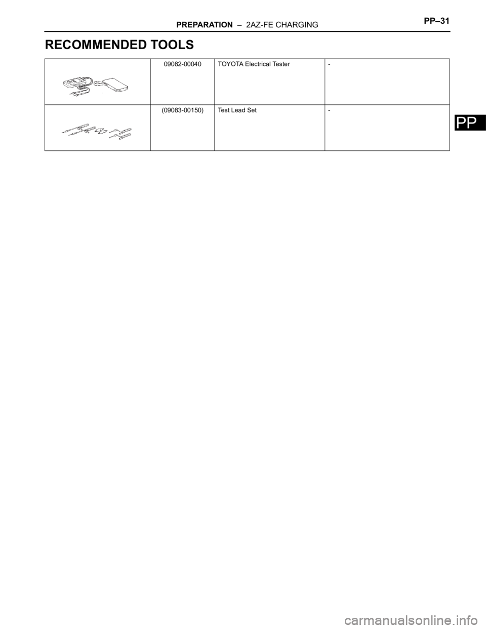
RECOMMENDED TOOLS
09082-00040 TOYOTA Electrical Tester -
(09083-00150) Test Lead Set -
Page 175 of 2000
PP–32PREPARATION – 2AZ-FE CHARGING
PP
EQUIPMENT
Ammeter -
Ohmmeter -
Service wire -
To r q u e w r e n c h -
Page 308 of 2000
PREPARATION – 2GR-FE CHARGINGPP–33
PP
RECOMMENDED TOOLS
09082-00040 TOYOTA Electrical Tester -
(09083-00150) Test Lead Set -
Page 309 of 2000
PP–34PREPARATION – 2GR-FE CHARGING
PP
EQUIPMENT
Ammeter -
Ohmmeter -
Service wire -
To r q u e w r e n c h -
Vernier calipers -
Page 338 of 2000
2AZ-FE CHARGING – CHARGING SYSTEMCH–3
CH
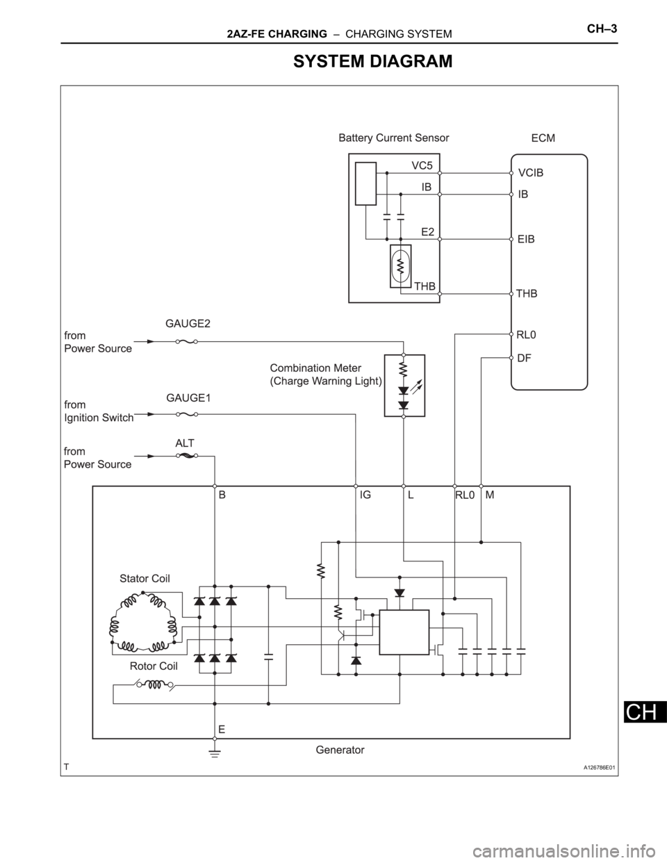
SYSTEM DIAGRAM
A126786E01
Page 339 of 2000
CH–42AZ-FE CHARGING – CHARGING SYSTEM
CH
ON-VEHICLE INSPECTION
1. CHECK BATTERY CONDITION
NOTICE:
If the battery is weak or if the engine is difficult to
start, perform the following procedures.
(a) Check the battery for damage and deformation. If
severe damage, deformation or leakage is found,
replace the battery.
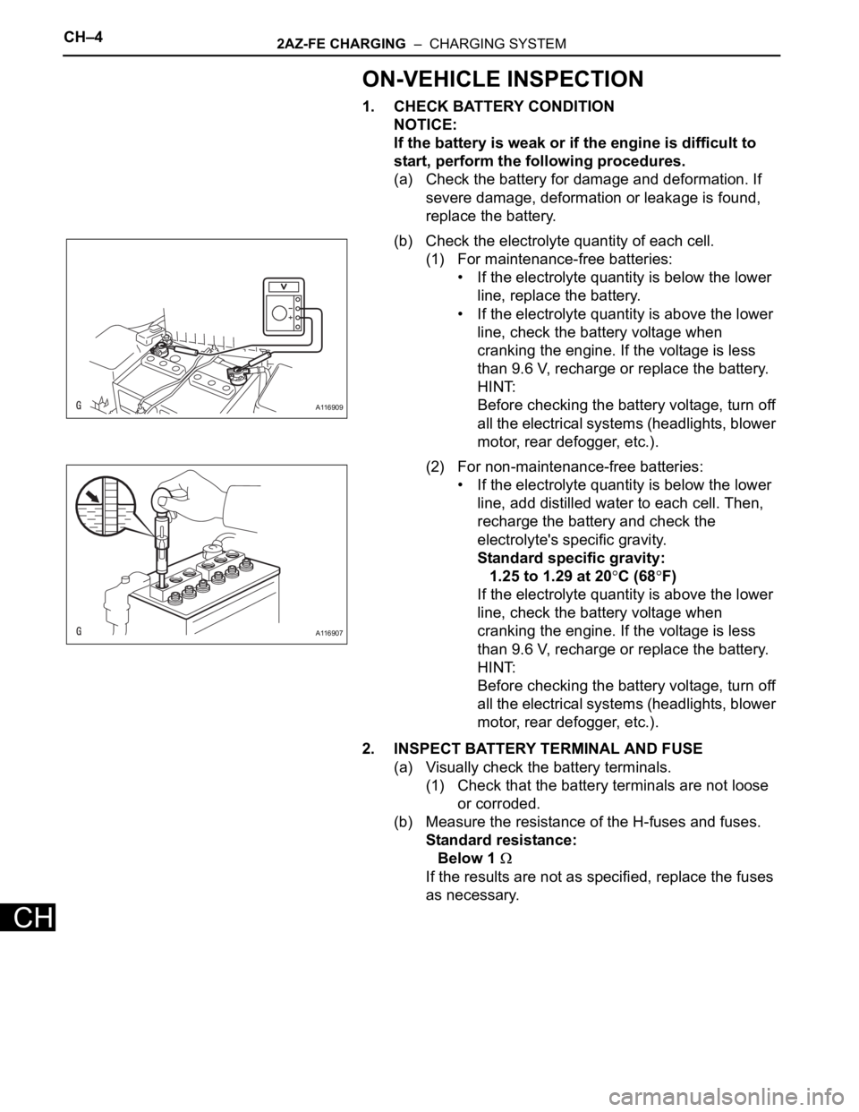
(b) Check the electrolyte quantity of each cell.
(1) For maintenance-free batteries:
• If the electrolyte quantity is below the lower
line, replace the battery.
• If the electrolyte quantity is above the lower
line, check the battery voltage when
cranking the engine. If the voltage is less
than 9.6 V, recharge or replace the battery.
HINT:
Before checking the battery voltage, turn off
all the electrical systems (headlights, blower
motor, rear defogger, etc.).
(2) For non-maintenance-free batteries:
• If the electrolyte quantity is below the lower
line, add distilled water to each cell. Then,
recharge the battery and check the
electrolyte's specific gravity.
Standard specific gravity:
1.25 to 1.29 at 20
C (68F)
If the electrolyte quantity is above the lower
line, check the battery voltage when
cranking the engine. If the voltage is less
than 9.6 V, recharge or replace the battery.
HINT:
Before checking the battery voltage, turn off
all the electrical systems (headlights, blower
motor, rear defogger, etc.).
2. INSPECT BATTERY TERMINAL AND FUSE
(a) Visually check the battery terminals.
(1) Check that the battery terminals are not loose
or corroded.
(b) Measure the resistance of the H-fuses and fuses.
Standard resistance:
Below 1
If the results are not as specified, replace the fuses
as necessary.
A116909
A116907