Page 340 of 2000
2AZ-FE CHARGING – CHARGING SYSTEMCH–5
CH
3. INSPECT V-RIBBED BELT
(a) Visually check the belt for excessive wear, frayed
cords, etc.
If any defects are found, replace the V-ribbed belt.
HINT:
Cracks on the rib side of the belt are considered
acceptable. If the belt has chunks missing from the
ribs, it should be replaced.
(b) Check that the belt fits properly in the ribbed
grooves.
HINT:
Confirm by hand that the belt has not slipped out of
the grooves on the bottom of the pulley.
4. INSPECT GENERATOR WIRING
(a) Visually check the generator wiring.
(1) Check that the wiring is in good condition.
5. CHECK FOR ABNORMAL NOISES
(a) Listen for abnormal noises from the generator.
(1) Check that no abnormal noises are heard from
the generator while the engine is running.
6. INSPECT CHARGE WARNING LIGHT CIRCUIT
(a) Turn the ignition switch ON. Check that the charge
warning light comes on.
(b) Start the engine and check that the light goes off.
If the light does not operate as specified,
troubleshoot the charge warning light circuit.
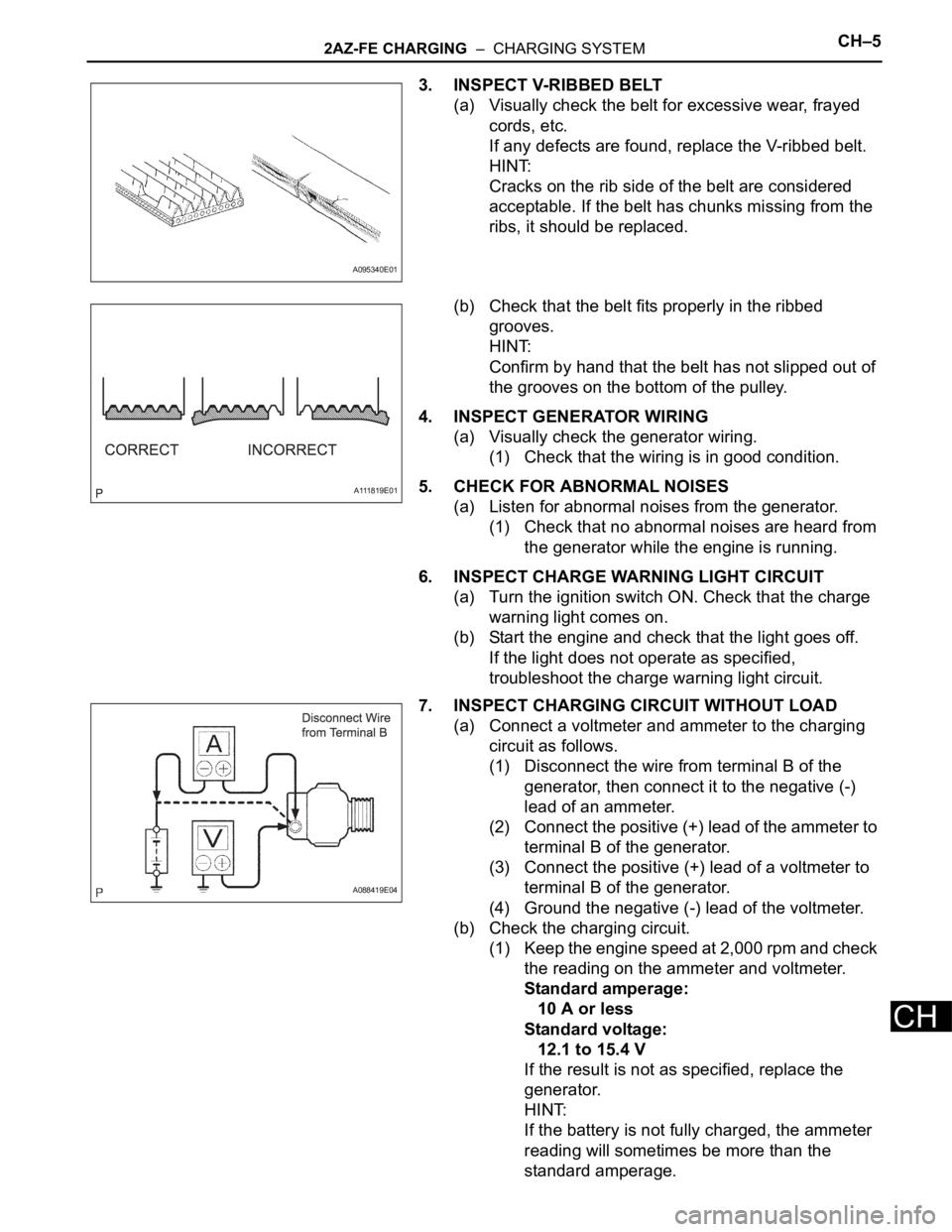
7. INSPECT CHARGING CIRCUIT WITHOUT LOAD
(a) Connect a voltmeter and ammeter to the charging
circuit as follows.
(1) Disconnect the wire from terminal B of the
generator, then connect it to the negative (-)
lead of an ammeter.
(2) Connect the positive (+) lead of the ammeter to
terminal B of the generator.
(3) Connect the positive (+) lead of a voltmeter to
terminal B of the generator.
(4) Ground the negative (-) lead of the voltmeter.
(b) Check the charging circuit.
(1) Keep the engine speed at 2,000 rpm and check
the reading on the ammeter and voltmeter.
Standard amperage:
10 A or less
Standard voltage:
12.1 to 15.4 V
If the result is not as specified, replace the
generator.
HINT:
If the battery is not fully charged, the ammeter
reading will sometimes be more than the
standard amperage.
A095340E01
A111819E01
A088419E04
Page 341 of 2000
CH–62AZ-FE CHARGING – CHARGING SYSTEM
CH
8. INSPECT CHARGING CIRCUIT WITH LOAD
(a) With the engine running at 2,000 rpm, turn the high
beam headlights ON and turn the heater blower
switch to the "HI" position.
(b) Check the reading on the ammeter.
Standard amperage:
30 A or more
If the ammeter reading is less than the standard
amperage, repair the generator.
HINT:
If the battery is fully charged, the indication will
sometimes be less than the standard amperage. If
this is the case, add more electrical load (operate
the wipers, rear window defogger, etc.) and check
the reading on the ammeter again.
Page 342 of 2000
2GR-FE CHARGING – CHARGING SYSTEMCH–3
CH
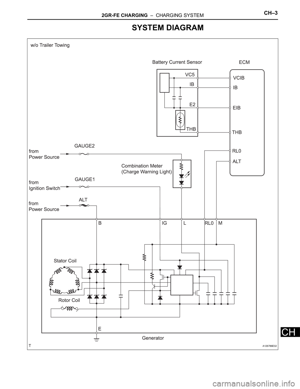
SYSTEM DIAGRAM
A126786E02
Page 343 of 2000
CH–42GR-FE CHARGING – CHARGING SYSTEM
CH
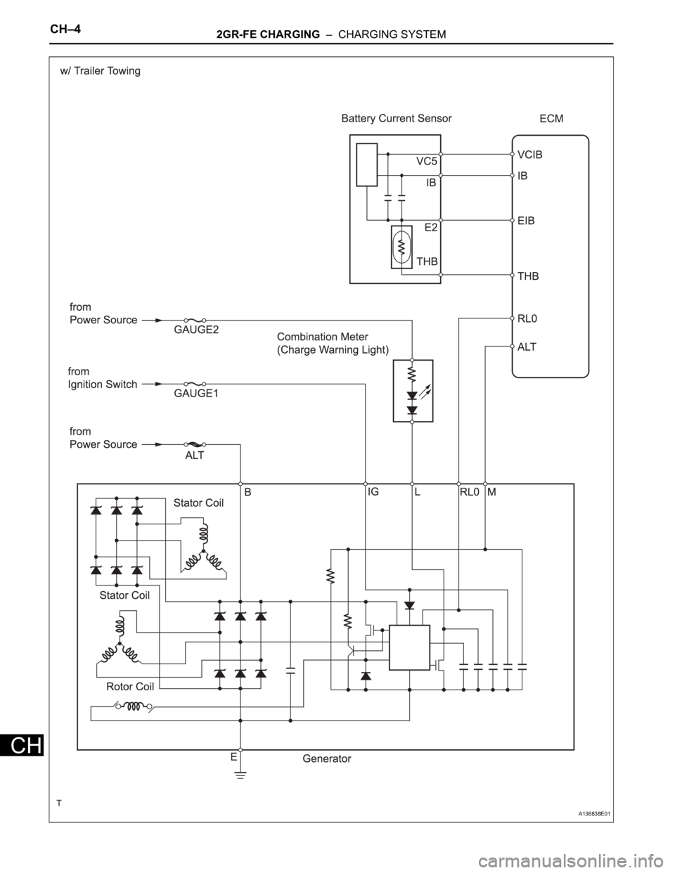
A136838E01
Page 487 of 2000

2AZ-FE ENGINE CONTROL SYSTEM – SFI SYSTEMES–33
ES
HINT:
*: The ECM terminal voltage is constant regardless of the
output voltage from the sensor.
M- (B30-41) - ME01 (B30-43) W - W-B Throttle actuator Idling with warm enginePulse generation (see
waveform 10)
FC (A9-7) - E1 (B30-104) W - BR Fuel pump controlIgnition switch ON 9 to 14 V
Idling Below 1.5 V
W (A9-24) - E1 (B30-104) R - BR MILIgnition switch ON Below 1.5 V
Idling 9 to 14 V
TC (A9-27) - E1 (B30-104) G - BR Terminal TC of DLC3 Ignition switch ON 9 to 14 V
TACH (A9-15) - E1 (B30-104) GR - BR Engine speed IdlingPulse generation (see
waveform 11)
VPMP (A9-42) - E1 (B30-104) W - BRVent valve (built into
canister pump module)Ignition switch ON 9 to 14 V
MPMP (A9-34) - E1 (B30-104) B - BRLeak detection pump (built
into canister pump
module)Leak detection pump OFF Below 3 V
Leak detection pump ON 9 to 14 V
VCPP (B30-70) - EPPM (B30-94) Y - BRPower source for canister
pressure sensor (specific
voltage)Ignition switch ON 4.5 to 5.5 V
PPMP (B30-71) - EPPM (B30-94) V - BRCanister pressure sensor
(built into canister pump
module)Ignition switch ON 3 to 3.6 V
ELS1 (A9-31) - E1 (B30-104) O - BR Electric loadTaillight switch ON 7.5 to 14 V
Taillight switch OFF Below 1.5 V
ELS3 (A9-33) - E1 (B30-104) G - BR Electric loadDefogger switch ON 7.5 to 14 V
Defogger switch OFF Below 1.5 V
FANL (A9-21) - E1 (B30-104) R - BR Fan No. 1 relayIgnition switch ON 9 to 14 V
Idling with A/C ON, or high engine
coolant temperatureBelow 1.5 V
FANH (A9-22) - E1 (B30-104) W - BR Fan No. 2 relayIdling with high engine coolant
temperatureBelow 1.5 V
ALT (B30-50) - E1 (B30-104) B - BR Generator Ignition switch ON 9 to 14 V
CANH (A9-41) - E1 (B30-104) Y - BR CAN communication line Ignition switch ONPulse generation (see
waveform 12)
CANL (A9-49) - E1 (B30-104) W - BR CAN communication line Ignition switch ONPulse generation (see
waveform 13)
VCIB (B30-69) - EIB (B30-92) R - BR Battery current sensor Ignition switch ON 4.5 to 5.5 V
IB (B30-68) - EIB (B30-92) B - BR Battery current sensor Ignition switch ON 0.5 to 2.5 V
THB (B30-120) - EIB (B30-92) LG - BRBattery temperature
sensorIgnition switch ON, Battery
temperature -30 to 80
C (-22 to
176
F)0.5 to 4.5 V
RLO (B30-51) - E1 (B30-104) GR - BR GeneratorAfter engine warmed up, during
charging control, vehicle driven at
constant speedPulse generation (see
waveform 14)
RLO (B30-51) - E1 (B30-104) GR - BR GeneratorAfter engine warmed up, during
charging control, vehicle
acceleratedPulse generation (see
waveform 15)
RLO (B30-51) - E1 (B30-104) GR - BR GeneratorAfter engine warmed up, during
charging control, vehicle
deceleratedPulse generation (see
waveform 16) Symbols (Terminal No.) Wiring Colors Terminal Descriptions ConditionsSpecified
Conditions
Page 490 of 2000

ES–362AZ-FE ENGINE CONTROL SYSTEM – SFI SYSTEM
ES
10. WAVEFORM 10
Throttle actuator negative terminal
HINT:
The duty ratio varies depending on the throttle actuator
operation.
11 . WAVE F OR M 11
Engine speed signal
HINT:
The wavelength becomes shorter as the engine rpm
increases.
12. WAVEFORM 12
CAN communication signal
HINT:
The waveform varies depending on the CAN
communication signal.
13. WAVEFORM 13
CAN communication signal
HINT:
The waveform varies depending on the CAN
communication signal.
14. WAVEFORM 14
Generator
HINT:
A constant value is not output, as the duty ratio varies
depending on the electrical load and battery condition.
A093275E03
ECM Terminal Names Between M- and ME01
Tester Ranges 5 V/DIV., 1 msec./DIV.
Conditions Idling with warm engine
A093225E01
ECM Terminal Names Between TACH and E1
Tester Ranges 5 V/DIV., 10 msec./DIV.
Conditions Idling
A086154E01
ECM Terminal Names Between CANH and E1
Tester Ranges 1 V/DIV., 10
sec./DIV.
Conditions Engine stops and ignition switch ON
A086155E01
ECM Terminal Names Between CANL and E1
Tester Ranges 1 V/DIV., 10
sec./DIV.
Conditions Engine stops and ignition switch ON
A084458
ECM Terminal Names Between RLO and E1
Tester Ranges 2 V/DIV., 50 msec./DIV.
Conditions After engine warmed up, during
charging control, vehicle driven at
constant speed
Page 491 of 2000
2AZ-FE ENGINE CONTROL SYSTEM – SFI SYSTEMES–37
ES
15. WAVEFORM 15
Generator
HINT:
A constant value is not output, as the duty ratio varies
depending on the electrical load and battery condition.
16. WAVEFORM 16
Generator
HINT:
A constant value is not output, as the duty ratio varies
depending on the electrical load and battery condition.
A084457
ECM Terminal Names Between RLO and E1
Tester Ranges 2 V/DIV., 50 msec./DIV.
Conditions After engine warmed up, during
charging control, vehicle accelerated
A084456
ECM Terminal Names Between RLO and E1
Tester Ranges 2 V/DIV., 50 msec./DIV.
Conditions After engine warmed up, during
charging control, vehicle decelerated
Page 561 of 2000

2GR-FE ENGINE CONTROL SYSTEM – SFI SYSTEMES–37
ES
HINT:
*: The ECM terminal voltage is constant regardless
of the output voltage from the sensor.
(b) WAVEFORM 1
Camshaft timing oil control valve (OCV)
PPMP (B30-77) - EPPM (B30-76) L - BR Canister pressure sensor
(built into canister pump
module)Ignition switch ON 3 to 3.6 V
ELS (A9-31) - E1 (B30-81) O - BR Electric load Taillight switch ON7.5 to 14 V
Taillight switch OFF Below 1.5 V
ELS2 (A9-33) - E1 (B30-81) G - BR Electric load Defogger switch ON7.5 to 14 V
Defogger switch OFF Below 1.5 V
ALT (B30-32) - E1 (B30-81) P - BR Generator Ignition switch ON 9 to 14 V
CANH (A9-41) - E1 (B30-81) Y - BR CAN communication line Ignition switch ON Pulse generation (see
waveform 12)
CANL (A9-49) - E1 (B30-81) W - BR CAN communication line Ignition switch ON Pulse generation (see
waveform 13)
VCIB (B30-80) - EIB (B30-101) LG - P Battery current sensor Ignition switch ON 4.5 to 5.5 V
IB (B30-100) - EIB (B30-101) R - P Battery current sensor Ignition switch ON 0.5 to 2.5 V
THB (B30-103) - EIB (B30-101) G-R - P Battery temperature
sensorIgnition switch ON, battery
temperature -30 to 80
C (-22 to
176
F)0.5 to 4.5 V
RLO (B30-31) - E1 (B30-81) Y - BR Generator After engine warmed up, during
charging control, vehicle driven at
constant speedPulse generation (see
waveform 14)
RLO (B30-31) - E1 (B30-81) Y - BR Generator After engine warmed up, during
charging control, vehicle
acceleratedPulse generation (see
waveform 15)
RLO (B30-31) - E1 (B30-81) Y - BR Generator After engine warmed up, during
charging control, vehicle
deceleratedPulse generation (see
waveform 16)
AICV (A9-4) - E1 (B30-81) L - BR VSV for air intake control
system operation signalIgnition switch ON 9 to 14 V
ACIS (B30-107) - E1 (B30-81) R - BR VSV for ACIS (Acoustic
Control Induction System)
operation signalIgnition switch ON 9 to 14 V Symbol (Terminal No.) Wiring Color Terminal Description Condition Specified Condition
A093229E02
Symbol (Terminal No.) Between OC1+ and OC1-
Between OC2+ and OC2-
Between OE1+ and OE1-
Between OE2+ and OE2-
Tester Range 5 V/DIV., 1 msec./DIV.
Condition Idling