2006 TOYOTA RAV4 Parts list
[x] Cancel search: Parts listPage 1350 of 2000

TF–22GF1A TRANSFER – ACTIVE TORQUE CONTROL 4WD SYSTEM
TF
2. PERFORM ACTIVE TEST
HINT:
Performing the intelligent tester's (with CAN VIM)
ACTIVE TEST allows switch and other items to be
operated without removing any parts. Performing the
ACTIVE TEST early in troubleshooting is one way to
save time. The DATA LIST can be displayed during the
ACTIVE TEST.
(a) Connect the intelligent tester (with CAM VIN) to the
DLC3.
(b) Turn the ignition switch ON.
(c) Perform the ACTIVE TEST according to the display
on the tester.
4WD control ECU
Skid control ECU
Item Test Details Diagnostic Note
4WD WARN LAMP 4WD indicator light ON / OFF
ON: 4WD indicator light ON
OFF: 4WD indicator light OFFObserve combination meter
LOCK LAMP 4WD lock light / ON / OFF
OFF: 4WD lock switch OFF
ON: 4WD lock switch ONObserve combination meter
Item Test Details Diagnostic Note
SLIP INDI LAMP SLIP indicator Light / ON / OFF
ON: SLIP indicator light ON
OFF: SLIP indicator light OFFObserve combination meter
Page 1490 of 2000
TW–18TIRE AND WHEEL – TIRE PRESSURE WARNING SYSTEM
TW
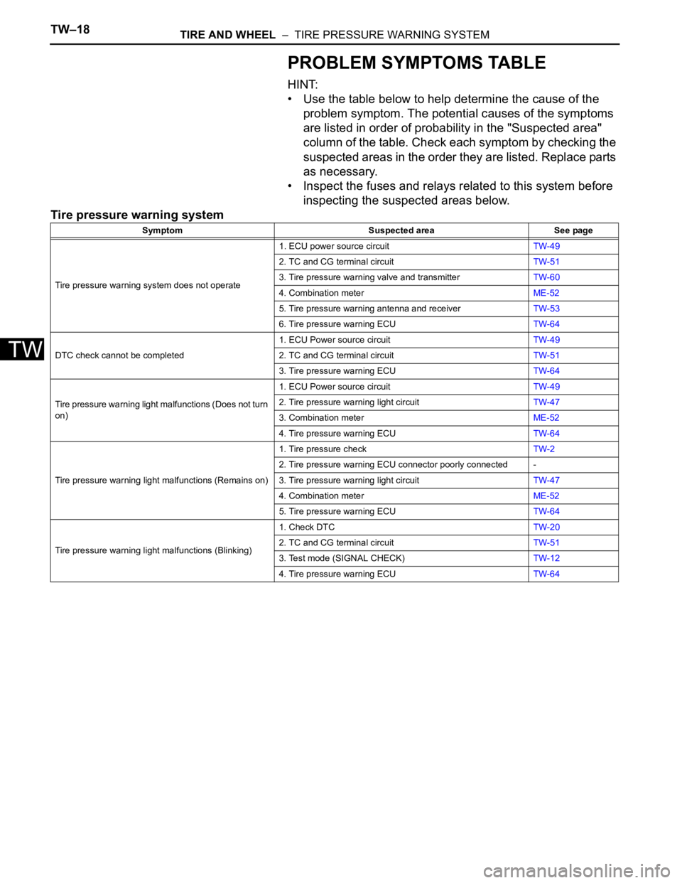
PROBLEM SYMPTOMS TABLE
HINT:
• Use the table below to help determine the cause of the
problem symptom. The potential causes of the symptoms
are listed in order of probability in the "Suspected area"
column of the table. Check each symptom by checking the
suspected areas in the order they are listed. Replace parts
as necessary.
• Inspect the fuses and relays related to this system before
inspecting the suspected areas below.
Tire pressure warning system
Symptom Suspected area See page
Tire pressure warning system does not operate1. ECU power source circuitTW-49
2. TC and CG terminal circuitTW-51
3. Tire pressure warning valve and transmitterTW-60
4. Combination meterME-52
5. Tire pressure warning antenna and receiverTW-53
6. Tire pressure warning ECUTW-64
DTC check cannot be completed1. ECU Power source circuitTW-49
2. TC and CG terminal circuitTW-51
3. Tire pressure warning ECUTW-64
Tire pressure warning light malfunctions (Does not turn
on)1. ECU Power source circuitTW-49
2. Tire pressure warning light circuitTW-47
3. Combination meterME-52
4. Tire pressure warning ECUTW-64
Tire pressure warning light malfunctions (Remains on)1. Tire pressure checkTW-2
2. Tire pressure warning ECU connector poorly connected -
3. Tire pressure warning light circuitTW-47
4. Combination meterME-52
5. Tire pressure warning ECUTW-64
Tire pressure warning light malfunctions (Blinking)1. Check DTCTW-20
2. TC and CG terminal circuitTW-51
3. Test mode (SIGNAL CHECK)TW-12
4. Tire pressure warning ECUTW-64
Page 1496 of 2000

TW–24TIRE AND WHEEL – TIRE PRESSURE WARNING SYSTEM
TW
DATA LIST / ACTIVE TEST
1. READ DATA LIST
HINT:
Using the intelligent tester's DATA LIST allows switch,
actuator and other item values to be read without
removing any parts. Reading the Data List early in
troubleshooting is one way to save time.
(a) Connect the intelligent tester (with CAN VIM) to the
DLC3.
(b) Turn the ignition switch ON.
(c) Read the DATA LIST according to the display on the
tester.
Tire pressure warning ECU
Item Measurement item/ Range
(Display)Normal Condition Diagnostic Note
MODE STATUS Tire pressure warning system
mode / NORMAL or REG 2nd or
REG M or TEST NORMAL: Normal mode TEST:
Test mode
REG 2nd: 2nd registration
REG M: Main registration
TEST: Test mode -
MAIN TIRE Number of main tire IDs to be
registered / 0 or 1 or 2 or 3 or 4
or 5 0 to 5 should be displayed -
VEHICLE SPEED Vehicle speed reading /
min.: 0 km/h (0 mph),
max.: 255 km/h (158 mph)Actual vehicle speed Speed indicated on the
combination meter
REGIT ID1 CODE Registered ID1 code / min.: 0,
max.: FFFFFFF The ID No. registered in
transmitter ID1 is displayed -
REGIT ID2 CODE Registered ID2 code / min.: 0,
max.: FFFFFFF The ID No. registered in
transmitter ID2 is displayed -
REGIT ID3 CODE Registered ID3 code / min.: 0,
max.: FFFFFFF The ID No. registered in
transmitter ID3 is displayed -
REGIT ID4 CODE Registered ID4 code / min.: 0,
max.: FFFFFFF The ID No. registered in
transmitter ID4 is displayed -
REGIT ID5 CODE Registered ID5 code / min.: 0,
max.: FFFFFFF The ID No. registered in
transmitter ID5 is displayed -
TRANS STATUS ID code transmission status /
FINISH or NOW FINISH or NOW -
TIREPRESS1 ID1 tire pressure /
min.: 0 kPa (0 kgf/cm
2, 0 psi)
max.: 637.5 kPa (6.48 kgf/cm2,
92.2 psi) Actual tire pressure -
TIREPRESS2 ID2 tire pressure /
min.: 0 kPa (0 kgf/cm
2, 0 psi)
max.: 637.5 kPa (6.48 kgf/cm2,
92.2 psi) Actual tire pressure -
TIREPRESS3 ID3 tire pressure /
min.: 0 kPa (0 kgf/cm
2, 0 psi)
max.: 637.5 kPa (6.48 kgf/cm2,
92.2 psi) Actual tire pressure -
TIREPRESS4 ID4 tire pressure /
min.: 0 kPa (0 kgf/cm
2, 0 psi)
max.: 637.5 kPa (6.48 kgf/cm2,
92.2 psi) Actual tire pressure -
TIREPRESS5 ID5 tire pressure /
min.: 0 kPa (0 kgf/cm
2, 0 psi)
max.: 637.5 kPa (6.48 kgf/cm2,
92.2 psi) Actual tire pressure -
Page 1545 of 2000
BC–42BRAKE CONTROL – VEHICLE STABILITY CONTROL SYSTEM
BC
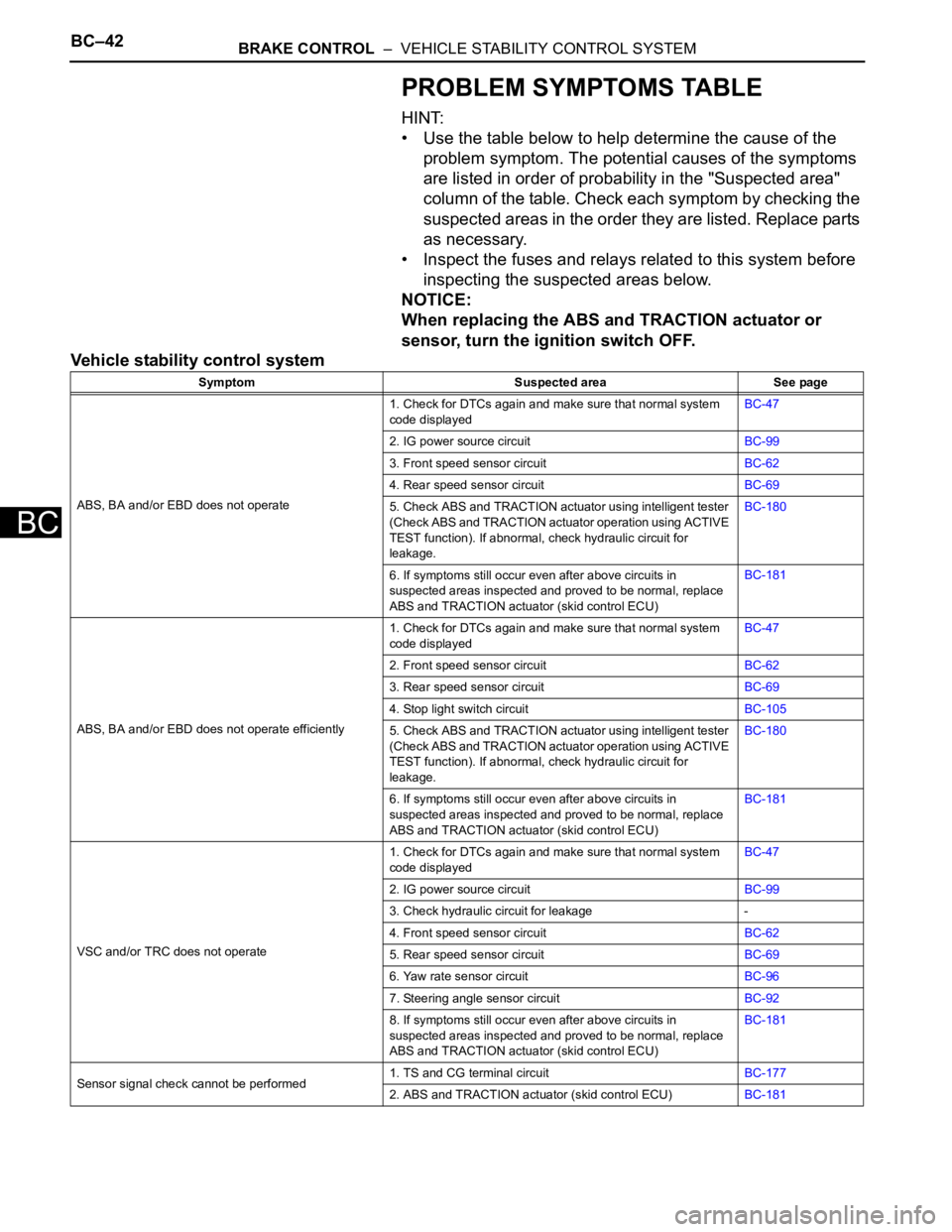
PROBLEM SYMPTOMS TABLE
HINT:
• Use the table below to help determine the cause of the
problem symptom. The potential causes of the symptoms
are listed in order of probability in the "Suspected area"
column of the table. Check each symptom by checking the
suspected areas in the order they are listed. Replace parts
as necessary.
• Inspect the fuses and relays related to this system before
inspecting the suspected areas below.
NOTICE:
When replacing the ABS and TRACTION actuator or
sensor, turn the ignition switch OFF.
Vehicle stability control system
Symptom Suspected area See page
ABS, BA and/or EBD does not operate1. Check for DTCs again and make sure that normal system
code displayedBC-47
2. IG power source circuitBC-99
3. Front speed sensor circuitBC-62
4. Rear speed sensor circuitBC-69
5. Check ABS and TRACTION actuator using intelligent tester
(Check ABS and TRACTION actuator operation using ACTIVE
TEST function). If abnormal, check hydraulic circuit for
leakage.BC-180
6. If symptoms still occur even after above circuits in
suspected areas inspected and proved to be normal, replace
ABS and TRACTION actuator (skid control ECU)BC-181
ABS, BA and/or EBD does not operate efficiently1. Check for DTCs again and make sure that normal system
code displayedBC-47
2. Front speed sensor circuitBC-62
3. Rear speed sensor circuitBC-69
4. Stop light switch circuitBC-105
5. Check ABS and TRACTION actuator using intelligent tester
(Check ABS and TRACTION actuator operation using ACTIVE
TEST function). If abnormal, check hydraulic circuit for
leakage.BC-180
6. If symptoms still occur even after above circuits in
suspected areas inspected and proved to be normal, replace
ABS and TRACTION actuator (skid control ECU)BC-181
VSC and/or TRC does not operate1. Check for DTCs again and make sure that normal system
code displayedBC-47
2. IG power source circuitBC-99
3. Check hydraulic circuit for leakage -
4. Front speed sensor circuitBC-62
5. Rear speed sensor circuitBC-69
6. Yaw rate sensor circuitBC-96
7. Steering angle sensor circuitBC-92
8. If symptoms still occur even after above circuits in
suspected areas inspected and proved to be normal, replace
ABS and TRACTION actuator (skid control ECU)BC-181
Sensor signal check cannot be performed1. TS and CG terminal circuitBC-177
2. ABS and TRACTION actuator (skid control ECU)BC-181
Page 1559 of 2000

BC–56BRAKE CONTROL – VEHICLE STABILITY CONTROL SYSTEM
BC
DATA LIST / ACTIVE TEST
1. READ DATA LIST
HINT:
Using the intelligent tester's DATA LIST allows switch,
sensor, actuator and other item values to be read without
out removing any parts. Reading the DATA LIST early in
troubleshooting is one way to save time.
(a) Connect the intelligent tester (with CAN VIM) to the
DLC3.
(b) Turn the ignition switch ON.
(c) Turn the intelligent tester on.
(d) Read the DATA LIST according to the display on the
tester.
Skid control ECU
Tester Display Measurement Item/Range Normal Condition Diagnostic Note
ABS WARN LAMP ABS warning light / ON or OFF ON: ABS warning light ON
OFF: ABS warning light OFF-
VSC WARN LAMP VSC warning light / ON or OFF ON: VSC warning light ON
OFF: VSC warning light OFF-
BRAKE WARN LAMP Brake warning light / ON or OFF ON: Brake warning light ON
OFF: Brake warning light OFF-
SLIP INDI LAMP Slip indicator light / ON or OFF ON: Slip indicator light ON
OFF: Slip indicator light OFF-
D-HILL LIGHT*9 Downhill assist control indicator
light / ON or OFFON: Downhill assist control switch
ON
OFF: Downhill assist control
switch OFF-
AUTO LSD LAMP*10 AUTO LSD indicator light / ON or
OFFON: Traction control switch ON
OFF: Traction control switch OFF-
BUZZER Skid control buzzer / ON or OFF ON: Buzzer ON
OFF: Buzzer OFF-
STOP LAMP SW Stop light switch / ON or OFF ON: Brake pedal depressed
OFF: Brake pedal released-
PARKING BRAKE SW Parking brake switch / ON or OFF ON: Parking brake applied
OFF: Parking brake released-
BRK PEDAL SW Brake pedal load sensing switch /
ON or OFFON: Brake pedal depressed
beyond the specified point
OFF: Brake pedal not depressed
beyond the specified point-
IDLE SW Main idle switch / ON or OFF ON: Accelerator pedal released
OFF: Accelerator pedal
depressed-
DAC SW*9 Downhill assist control switch /
ON or OFFON: Downhill assist control switch
ON
ON: Downhill assist control switch
ON-
AUTO LSD SW*10 AUTO LSD switch / ON or OFF ON: AUTO LSD switch ON
ON: AUTO LSD switch ON-
GEAR POSITION Gear position information / P/N,
R, 1st-6th, FAIL, NOT R--
LEVER POSITION Shift lever position information / P/
N, R, D/M, 1st-6th/B, FAIL--
SHIFT INFO Shift information / ON or OFF ON: During gear change -
MAS CYL PRESS 1 Master cylinder pressure sensor 1
reading / min.: 0 V, max.: 5 VWhen brake pedal released: 0.3
to 0.9 VReading increases when brake
pedal depressed
ZERO M/C SEN Memorized zero point value of
master cylinder pressure sensor /
min.: -12.5 MPa, max.: 12.4 MPaMin.: -12.5 MPa
Max.: 12.4 MPa-
Page 1563 of 2000

BC–60BRAKE CONTROL – VEHICLE STABILITY CONTROL SYSTEM
BC
2. PARFORM ACTIVE TEST
HINT:
Performing the intelligent tester's ACTIVE TEST allows
relay, VSV, actuator and other items to be operated
without removing any parts. Performing the ACTIVE
TEST early in troubleshooting is one way to save time.
The DATA LIST can be displayed during the ACTIVE
TEST.
(a) Connect the intelligent tester (with CAN VIM) to the
DLC3.
(b) Turn the ignition switch ON.
(c) Turn the intelligent tester on.
(d) Perform the ACTIVE TEST according to the display
on the tester.
HINT:
• The ignition switch must be turned ON to
proceed to the ACTIVE TEST using the
intelligent tester.
• The ACTIVE TESTs of the ABS solenoid, ABS
motor relay, ABS warning light and BRAKE
warning light are available when the vehicle is
stopped.
• The motors stop automatically after 5 seconds of
activation to prevent them from being damaged.
When the motors are driven repeatedly, certain
intervals are required.
• Each solenoid stops automatically after 2
seconds of activation to prevent them from being
damaged, and can be operated again after a
certain interval.
• Do not depress the brake pedal while only the
pressure reduction solenoid valves are on.
• Do not drive 2 or more solenoids simultaneously
except to operate the pressure holding solenoid
valves and pressure reduction solenoid valves of
each wheel.
Skid control ECU
Tester Display Test Part Control Range
ABS WARN LAMP Turns ABS warning light ON / OFF Observe combination meter
VSC WARN LAMP Turns VSC warning light ON / OFF Observe combination meter
BRAKE WARN LAMP Turns Brake warning light ON / OFF Observe combination meter
SLIP INDI LAMP Turns Slip indicator light ON / OFF Observe combination meter
D-HILL LIGHT*1 Turns downhill assist control indicator light ON /
OFFObserve combination meter
AUTO LSD LAMP*2 Turns AUTO LSD indicator light ON / OFF Observe combination meter
BUZZER Turns skid control buzzer ON / OFF Buzzer can be heard
STP LAMP RELAY Turns stop light relay (BRK relay) ON / OFF Operation sound of motor can be heard
SOL RELAY Turns ABS solenoid relay ON / OFF -
MOTOR RELAY Turns ABS motor relay ON / OFF Operation sound of motor can be heard
SRLR Turns ABS solenoid (SRLR) ON / OFF Operation sound of solenoid (clicking sound)
can be heard
SRLH Turns ABS solenoid (SRLH) ON / OFF Operation sound of solenoid (clicking sound)
can be heard
Page 1565 of 2000
BRAKE – BRAKE SYSTEMBR–5
BR
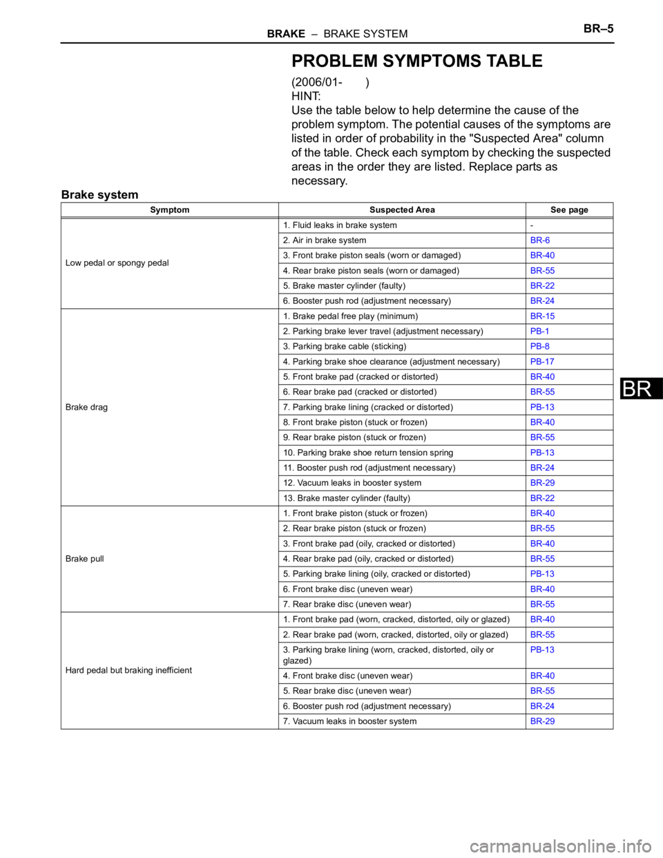
PROBLEM SYMPTOMS TABLE
(2006/01- )
HINT:
Use the table below to help determine the cause of the
problem symptom. The potential causes of the symptoms are
listed in order of probability in the "Suspected Area" column
of the table. Check each symptom by checking the suspected
areas in the order they are listed. Replace parts as
necessary.
Brake system
Symptom Suspected Area See page
Low pedal or spongy pedal1. Fluid leaks in brake system -
2. Air in brake systemBR-6
3. Front brake piston seals (worn or damaged)BR-40
4. Rear brake piston seals (worn or damaged)BR-55
5. Brake master cylinder (faulty)BR-22
6. Booster push rod (adjustment necessary)BR-24
Brake drag1. Brake pedal free play (minimum)BR-15
2. Parking brake lever travel (adjustment necessary)PB-1
3. Parking brake cable (sticking)PB-8
4. Parking brake shoe clearance (adjustment necessary)PB-17
5. Front brake pad (cracked or distorted)BR-40
6. Rear brake pad (cracked or distorted)BR-55
7. Parking brake lining (cracked or distorted)PB-13
8. Front brake piston (stuck or frozen)BR-40
9. Rear brake piston (stuck or frozen)BR-55
10. Parking brake shoe return tension springPB-13
11. Booster push rod (adjustment necessary)BR-24
12. Vacuum leaks in booster systemBR-29
13. Brake master cylinder (faulty)BR-22
Brake pull1. Front brake piston (stuck or frozen)BR-40
2. Rear brake piston (stuck or frozen)BR-55
3. Front brake pad (oily, cracked or distorted)BR-40
4. Rear brake pad (oily, cracked or distorted)BR-55
5. Parking brake lining (oily, cracked or distorted)PB-13
6. Front brake disc (uneven wear)BR-40
7. Rear brake disc (uneven wear)BR-55
Hard pedal but braking inefficient1. Front brake pad (worn, cracked, distorted, oily or glazed)BR-40
2. Rear brake pad (worn, cracked, distorted, oily or glazed)BR-55
3. Parking brake lining (worn, cracked, distorted, oily or
glazed)PB-13
4. Front brake disc (uneven wear)BR-40
5. Rear brake disc (uneven wear)BR-55
6. Booster push rod (adjustment necessary)BR-24
7. Vacuum leaks in booster systemBR-29
Page 1608 of 2000
PS–8POWER STEERING – ELECTRONIC POWER STEERING SYSTEM
PS
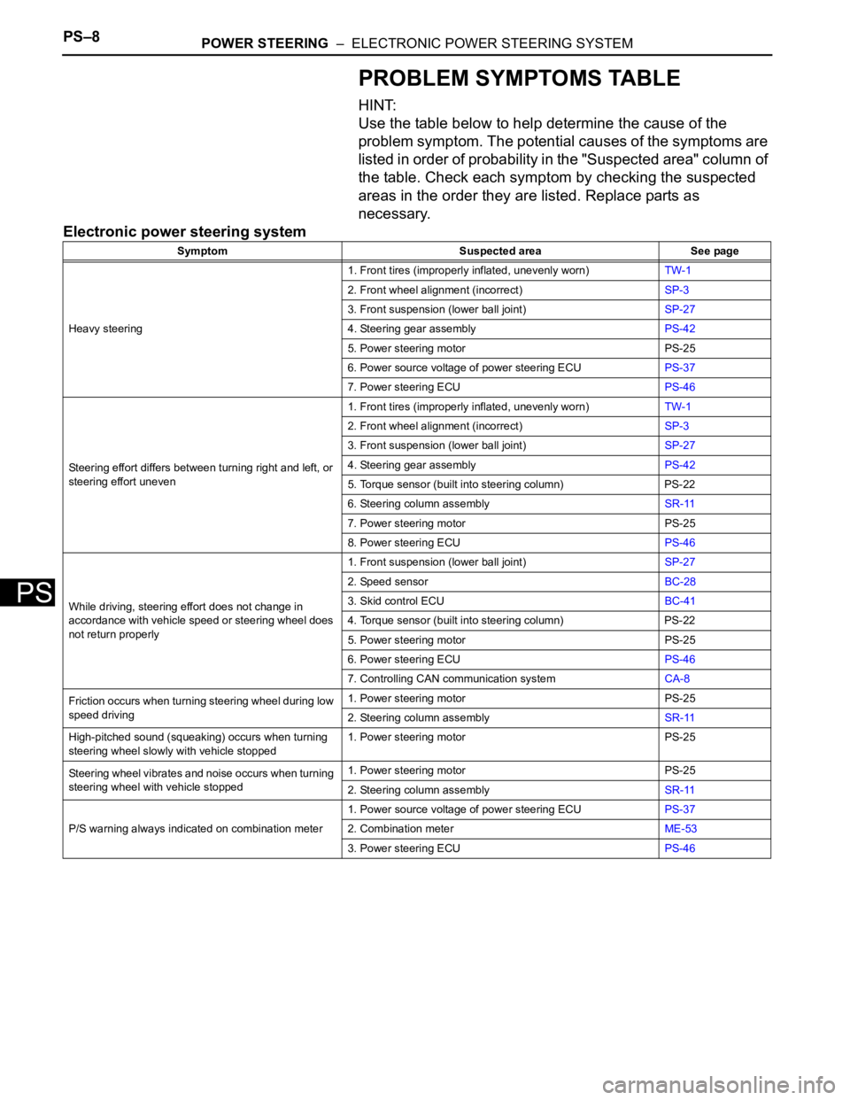
PROBLEM SYMPTOMS TABLE
HINT:
Use the table below to help determine the cause of the
problem symptom. The potential causes of the symptoms are
listed in order of probability in the "Suspected area" column of
the table. Check each symptom by checking the suspected
areas in the order they are listed. Replace parts as
necessary.
Electronic power steering system
Symptom Suspected area See page
Heavy steering1. Front tires (improperly inflated, unevenly worn)TW-1
2. Front wheel alignment (incorrect)SP-3
3. Front suspension (lower ball joint)SP-27
4. Steering gear assemblyPS-42
5. Power steering motor PS-25
6. Power source voltage of power steering ECUPS-37
7. Power steering ECUPS-46
Steering effort differs between turning right and left, or
steering effort uneven1. Front tires (improperly inflated, unevenly worn)TW-1
2. Front wheel alignment (incorrect)SP-3
3. Front suspension (lower ball joint)SP-27
4. Steering gear assemblyPS-42
5. Torque sensor (built into steering column) PS-22
6. Steering column assemblySR-11
7. Power steering motor PS-25
8. Power steering ECUPS-46
While driving, steering effort does not change in
accordance with vehicle speed or steering wheel does
not return properly1. Front suspension (lower ball joint)SP-27
2. Speed sensorBC-28
3. Skid control ECUBC-41
4. Torque sensor (built into steering column) PS-22
5. Power steering motor PS-25
6. Power steering ECUPS-46
7. Controlling CAN communication systemCA-8
Friction occurs when turning steering wheel during low
speed driving1. Power steering motor PS-25
2. Steering column assemblySR-11
High-pitched sound (squeaking) occurs when turning
steering wheel slowly with vehicle stopped1. Power steering motor PS-25
Steering wheel vibrates and noise occurs when turning
steering wheel with vehicle stopped1. Power steering motor PS-25
2. Steering column assemblySR-11
P/S warning always indicated on combination meter1. Power source voltage of power steering ECUPS-37
2. Combination meterME-53
3. Power steering ECUPS-46