2006 TOYOTA RAV4 Parts list
[x] Cancel search: Parts listPage 1750 of 2000

SB–12SEAT BELT – SEAT BELT WARNING SYSTEM
SB
DATA LIST / ACTIVE TEST
1. ACTIVE TEST
HINT:
Performing the intelligent tester ACTIVE TEST allows
relay, VSV, actuator and other items to be operated
without removing any parts. Performing the ACTIVE
TEST early in troubleshooting is one way to save time.
The DATA LIST can be displayed during the ACTIVE
TEST.
(a) Connect the intelligent tester to the DLC3.
(b) Turn the ignition switch ON.
(c) Perform the ACTIVE TEST according to the display
on the tester.
Center airbag sensor:
Item Test Details Diagnostic Note
D-BELT REMIND D-SEAT BELT warning light (OFF / ON) Confirm that the vehicle is stopped, engine
idling
P-BELT REMIND P-SEAT BELT warning light (OFF / ON) Confirm that the vehicle is stopped, engine
idling
Page 1784 of 2000
ENGINE IMMOBILISER – ENGINE IMMOBILISER SYSTEMEI–13
EI
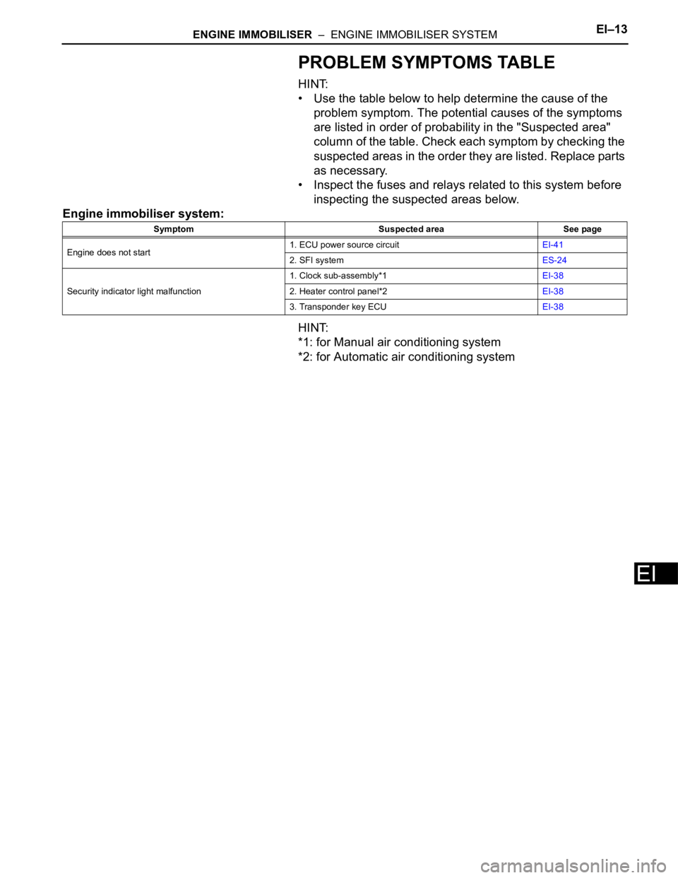
PROBLEM SYMPTOMS TABLE
HINT:
• Use the table below to help determine the cause of the
problem symptom. The potential causes of the symptoms
are listed in order of probability in the "Suspected area"
column of the table. Check each symptom by checking the
suspected areas in the order they are listed. Replace parts
as necessary.
• Inspect the fuses and relays related to this system before
inspecting the suspected areas below.
Engine immobiliser system:
HINT:
*1: for Manual air conditioning system
*2: for Automatic air conditioning system
Symptom Suspected area See page
Engine does not start1. ECU power source circuitEI-41
2. SFI systemES-24
Security indicator light malfunction1. Clock sub-assembly*1EI-38
2. Heater control panel*2EI-38
3. Transponder key ECUEI-38
Page 1792 of 2000

ENGINE IMMOBILISER – ENGINE IMMOBILISER SYSTEMEI–21
EI
DATA LIST / ACTIVE TEST
1. READ DATA LIST
HINT:
Using the intelligent tester's DATA LIST allows switch,
sensor, actuator and other item values to be read without
removing any parts. Reading the DATA LIST early in
troubleshooting is one way to save time.
(a) Connect the intelligent tester (with CAN VIM) to the
DLC3.
(b) Turn the ignition switch ON and turn the tester ON.
(c) Select the following menu items: DIAGNOSIS /
OBD/MOBD / IMMOBILISER / DATA LIST.
(d) Check the results by referring to the table below.
Transponder key ECU:
ItemMeasurement Item / Display
(Range)Normal Condition Diagnostic Note
KEY SWUnlock warning switch signal /
ON or OFFON: Key is in ignition key cylinder
OFF: No key is in ignition key
cylinder-
IG SW Ignition switch signal / ON or OFFON: Ignition switch ON (IG or
ACC)
OFF: Ignition switch OFF-
IMMOBILISERImmobiliser system status / SET
or UNSETSET: No key is in ignition key
cylinder
UNSET: Key is in ignition key
cylinder-
PERMIT (START)Engine starting control / OK or
NGOK: Engine start is permitted
NG: Engine start is not permitted-
RESPONSETransponder chip data / NG or
OKNG: Data error
OK: Data OK-
FRAME ERRORTransponder chip data / NG or
OKNG: Data error
OK: Data OK-
SERIAL NUMBERTransponder chip data / NG or
OKNG: Data error
OK: Data OK-
ENCRYPT CODETransponder chip data / NG or
OKNG: Data error
OK: Data OK-
STATUSTransponder chip data / NG or
OKNG: Data error
OK: Data OK-
BCCTransponder chip signal / NG or
OKNG: Incorrect data sent
OK: Correct data sent-
SUB KEYSub-key code signal / MATCH or
NOMATCHMATCH: Registered sub-key
code is sent
NOMATCH: Unmatched sub-key
code is sent-
MASTER KEYMaster key code signal / MATCH
or NOMATCHMATCH: Registered master key
code is sent
NOMATCH: Unmatched master
key code is sent-
REGIST SUB CODENumber of registered sub-keys /
min.: 0, max.: 15Number of registered sub-keys -
REGIST MAS CODENumber of registered master
keys / min.: 0, max.: 15Number of registered master
keys-
REG CODE SPACEKey registration code memory
space full / NOTFULL or FULLNOTFULL: Possible to register
more key codes
FULL: Cannot register any more
key codes-
Page 1793 of 2000

EI–22ENGINE IMMOBILISER – ENGINE IMMOBILISER SYSTEM
EI
2. PERFORM ACTIVE TEST
HINT:
Performing the intelligent tester's ACTIVE TEST allows
relay, VSV, actuator and other items to be operated
without removing any parts. Performing the ACTIVE
TEST early in troubleshooting is one way to save time.
The DATA LIST can be displayed during the ACTIVE
TEST.
(a) Connect the intelligent tester (with CAN VIM) to the
DLC3.
(b) Turn the ignition switch ON and turn the tester ON.
(c) Select the following menu items: DIAGNOSIS /
OBD/MOBD / IMMOBILISER / ACTIVE TEST.
(d) Perform the ACTIVE TEST by referring to the table
below.
Transponder key ECU:
+B+B judgment / NORMAL or
BREAKNORMAL: Battery supply is
normal
BREAK: Battery supply is
malfunctioning-
ANTENNA COILTransponder key coil condition /
NORMAL or FAILNORMAL: Transponder key coil
is normal
FAIL: Transponder key coil is
malfunctioning- ItemMeasurement Item / Display
(Range)Normal Condition Diagnostic Note
Item Test Details Diagnostic Note
SECURITY INDIC Turns security indicator light / ON or OFF -
Page 1813 of 2000
CC–14CRUISE CONTROL – CRUISE CONTROL SYSTEM
CC
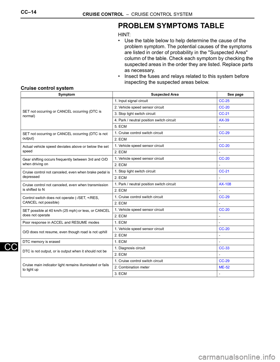
PROBLEM SYMPTOMS TABLE
HINT:
• Use the table below to help determine the cause of the
problem symptom. The potential causes of the symptoms
are listed in order of probability in the "Suspected Area"
column of the table. Check each symptom by checking the
suspected areas in the order they are listed. Replace parts
as necessary.
• Insect the fuses and relays related to this system before
inspecting the suspected areas below.
Cruise control system
Symptom Suspected Area See page
SET not occurring or CANCEL occurring (DTC is
normal)1. Input signal circuitCC-25
2. Vehicle speed sensor circuitCC-20
3. Stop light switch circuitCC-21
4. Park / neutral position switch circuitAX-39
5. ECM -
SET not occurring or CANCEL occurring (DTC is not
output)1. Cruise control switch circuitCC-29
2. ECM -
Actual vehicle speed deviates above or below the set
speed1. Vehicle speed sensor circuitCC-20
2. ECM -
Gear shifting occurs frequently between 3rd and O/D
when driving on1. Vehicle speed sensor circuitCC-20
2. ECM -
Cruise control not canceled, even when brake pedal is
depressed1. Stop light switch circuitCC-21
2. ECM -
Cruise control not canceled, even when transmission
is shifted to N1. Park / neutral position switch circuitAX-108
2. ECM -
Control switch does not operate (-/SET, +/RES,
CANCEL not possible)1. Cruise control switch circuitCC-29
2. ECM -
SET possible at 40 km/h (25 mph) or less, or CANCEL
does not operate1. Vehicle speed sensor circuitCC-20
2. ECM -
Poor response in ACCEL and RESUME modes 1. ECM -
O/D does not resume, even though road is not uphill1. Vehicle speed sensor circuitCC-20
2. ECM -
DTC memory is erased 1. ECM -
DTC is not output, or is output when it should not be1. Diagnosis circuitCC-33
2. ECM -
Cruise main indicator light remains illuminated or fails
to light up1. Cruise control switch circuitCC-29
2. Combination meterME-52
3. ECM -
Page 1820 of 2000

CRUISE CONTROL – CRUISE CONTROL SYSTEMCC–21
CC
DATA LIST / ACTIVE TEST
1. READ DATA LIST
HINT:
Using the intelligent tester's DATA LIST allows switch,
sensor, actuator and other item values to be read without
removing any parts. Reading the DATA LIST early in
troubleshooting is one way to save time.
(a) Connect the intelligent tester (with CAN VIM) to the
DLC3.
(b) Turn the ignition switch ON.
(c) Read the DATA LIST according to the display on the
tester.
ECM
Item Measurement Item / Display
(Range)Normal Condition Diagnostic Note
VEHICLE SPD Vehicle speed / min.: 0 km/h (0
mph) max.: 200 km/h (125 mph)Actual vehicle speed -
MEMORY SPD Vehicle speed / min.: 0 km/h (0
mph) max.: 200 km/h (125 mph)Actual vehicle speed stored in
memory-
THROTTLE Throttle operating angle / min.: 0
deg. max.: 125 deg.Actual demanded throttle angle -
CRUISE CONTROL Cruise control / ON or OFF ON: Cruise control is SET
OFF: Cruise control is UNSET-
MAIN SW (MAIN) Main switch (Main CPU) / ON or
OFFON: Main switch (Main CPU) is
SET
OFF: Main switch (Main CPU) is
UNSET-
CCS READY M Switch ready (Main CPU) / ON or
OFFON: Switch ready (Main CPU) is
SET
OFF: Switch ready (Main CPU) is
UNSET-
CCS INDICATOR M Switch indicator (Main CPU) / ON
or OFFON: Switch indicator (Main CPU)
is SET
OFF: Switch indicator (Main
CPU) is UNSET-
CANCEL SW CANCEL switch / ON or OFF ON: CANCEL switch is SET
OFF: CANCEL switch is UNSET-
SET/COAST SW - / SET switch / ON or OFF ON: - / SET switch is SET
OFF: - / SET switch is UNSET-
RES/ACC SW + / RES switch / ON or OFF ON: + / RES switch is SET
OFF: + / RES switch is UNSET-
STP LIGHT SW M Stop light switch signal (Main
CPU) / ON or OFFON: Brake pedal depressed
OFF: Brake pedal released-
SHIFT D POS Shift D position / ON or OFF ON: Shift is D or 3 position
OFF: Shift is except D or 3
position-
Page 1838 of 2000

LIGHTING – LIGHTING SYSTEMLI–7
LI
SYSTEM DESCRIPTION
1. LIGHTING SYSTEM
(a) Illumination control system (Illuminated entry
system):
When the doors are unlocked by a key or
transmitter operation, or when a door is opened or
closed, the illuminated entry system turns on the
room light, map light, foot light and ignition key
cylinder light*1 or transponder key amplifier*2.
(1) The main body ECU receives the following
signals (A).
• Door courtesy switch signal
• Door detection switch signal
• Ignition switch signal
(2) The main body ECU controls the following signal
based on the signals listed in A.
• Illumination operation signal
(3) The main body ECU controls the on/off and
fade-in/fade-out operation of the following parts.
•Room light
• Map light
•Foot light
• Ignition key cylinder light*1 or transponder
key amplifier*2
HINT:
*1: w/o Engine immobiliser system
*2: w/ Engine immobiliser system
(b) Battery saver system:
When the ignition switch is turned off and any of the
doors is open continuously for 20 minutes, the main
body ECU turns the illumination operation signal off.
As a result, the room light, map light, foot light and
ignition key cylinder lights*1 or transponder key
amplifier*2 turn off.
HINT:
*1: w/o Engine immobiliser system
*2: w/ Engine immobiliser system
(1) The main body ECU receives the following
signals (B).
• Door courtesy switch signal
• Ignition switch signal
(2) The main body ECU controls the following signal
based on the signals listed in B (C).
• Illumination operation signal
(3) The main body ECU controls the illumination
period of the following parts based on the
signals listed in C.
•Room light
• Map light
•Foot light
• Ignition key cylinder light*1 or transponder
key amplifier*2
HINT:
*1: w/o Engine immobiliser system
Page 1839 of 2000

LI–8LIGHTING – LIGHTING SYSTEM
LI
*2: w/ Engine immobiliser system
(c) Manual light control system:
This system functions when lights such as the
headlights and taillights are illuminated by manual
operation of the light control switch.
(1) The main body ECU receives the following
signals (D).
• Light control switch signal
• Headlight dimmer switch signal
• Front fog light switch signal
(2) The main body ECU controls the following
signals based on the signals listed in D (E).
• Headlight relay operation signal
• Taillight relay operation signal
• Daytime running light No. 2 relay operation
signal
• Daytime running light No. 3 relay operation
signal
• Daytime running light No. 4 relay operation
signal
• Front fog light relay operation signal
(3) The main body ECU controls the on/off
operation of the following parts based on the
signals listed in E.
• Headlight (LOW)
• Headlight (HIGH)
• Side marker light (front and rear)
• Front fog light
(d) Light auto turn off system:
When the headlights and taillights are illuminated by
the operation of the light control switch, if the
ignition switch is turned OFF, this system continues
illuminating the headlights and taillights for
approximately 30 seconds, and then turns off the
lights. However, when all the doors are locked
manually, using the door lock button, using the key
or pressing LOCK on the transmitter turns the
headlights and taillights off immediately.
(1) The main body ECU receives the following
signals (F).
• Door courtesy switch signal
• Ignition switch signal
(2) The main body ECU controls the following
signals based on the signals listed in F (G).
• Headlight relay operation signal
• Taillight relay operation signal
• Daytime running light No. 2 relay operation
signal
• Daytime running light No. 3 relay operation
signal
• Daytime running light No. 4 relay operation
signal
• Front fog light relay operation signal