Page 1455 of 2000
AH–14AXLE – FRONT AXLE HUB
AH
(b) Using a chisel and hammer, stake the hub nut.
11. ADD AUTOMATIC TRANSAXLE FLUID
(a) Add the automatic transaxle for U140F (see page
AX-152).
(b) Add the automatic transaxle for U241E (see page
AX-151).
(c) Add the automatic transaxle for U151E (see page
AX-177).
(d) Add the automatic transaxle for U151F (see page
AX-178).
12. CHECK FOR AUTOMATIC TRANSAXLE FLUID
LEAKAGE
13. INSTALL FRONT WHEEL
Torque: 103 N*m (1,050 kgf*cm, 76 ft.*lbf)
14. INSPECT AND ADJUST FRONT WHEEL ALIGNMENT
(a) Inspect and adjust the front wheel alignment (see
page SP-3).
15. CONNECT CABLE TO NEGATIVE BATTERY
TERMINAL
16. CHECK SPEED SENSOR SIGNAL
(a) Check the speed sensor signal (see page BC-44).
C129484
Page 1457 of 2000
AXLE – REAR AXLE HUB AND BEARINGAH–17
AH
REMOVAL
1. REMOVE REAR WHEEL
2. DISCONNECT CABLE FROM NEGATIVE BATTERY
TERMINAL
CAUTION:
Wait at least 90 seconds after disconnecting the
cable from the negative (-) battery terminal to
prevent airbag and seat belt pretensioner activation.
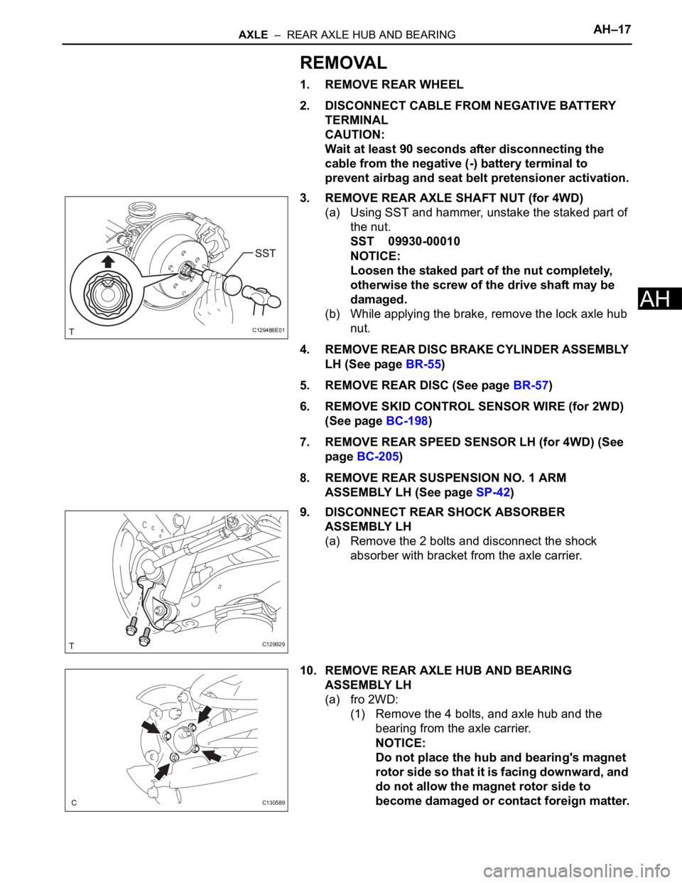
3. REMOVE REAR AXLE SHAFT NUT (for 4WD)
(a) Using SST and hammer, unstake the staked part of
the nut.
SST 09930-00010
NOTICE:
Loosen the staked part of the nut completely,
otherwise the screw of the drive shaft may be
damaged.
(b) While applying the brake, remove the lock axle hub
nut.
4. REMOVE REAR DISC BRAKE CYLINDER ASSEMBLY
LH (See page BR-55)
5. REMOVE REAR DISC (See page BR-57)
6. REMOVE SKID CONTROL SENSOR WIRE (for 2WD)
(See page BC-198)
7. REMOVE REAR SPEED SENSOR LH (for 4WD) (See
page BC-205)
8. REMOVE REAR SUSPENSION NO. 1 ARM
ASSEMBLY LH (See page SP-42)
9. DISCONNECT REAR SHOCK ABSORBER
ASSEMBLY LH
(a) Remove the 2 bolts and disconnect the shock
absorber with bracket from the axle carrier.
10. REMOVE REAR AXLE HUB AND BEARING
ASSEMBLY LH
(a) fro 2WD:
(1) Remove the 4 bolts, and axle hub and the
bearing from the axle carrier.
NOTICE:
Do not place the hub and bearing's magnet
rotor side so that it is facing downward, and
do not allow the magnet rotor side to
become damaged or contact foreign matter.
C129486E01
C129929
C130589
Page 1458 of 2000
AH–18AXLE – REAR AXLE HUB AND BEARING
AH
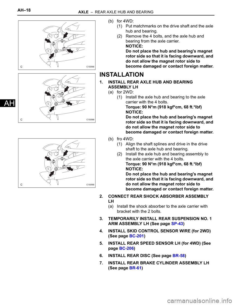
(b) for 4WD:
(1) Put matchmarks on the drive shaft and the axle
hub and bearing.
(2) Remove the 4 bolts, and the axle hub and
bearing from the axle carrier.
NOTICE:
Do not place the hub and bearing's magnet
rotor side so that it is facing downward, and
do not allow the magnet rotor side to
become damaged or contact foreign matter.
INSTALLATION
1. INSTALL REAR AXLE HUB AND BEARING
ASSEMBLY LH
(a) for 2WD:
(1) Install the axle hub and bearing to the axle
carrier with the 4 bolts.
Torque: 90 N*m (918 kgf*cm, 68 ft.*lbf)
NOTICE:
Do not place the hub and bearing's magnet
rotor side so that it is facing downward, and
do not allow the magnet rotor side to
become damaged or contact foreign matter.
(b) fro 4WD:
(1) Align the shaft splines and drive in the drive
shaft to the axle hub and bearing.
(2) Install the axle hub and bearing assembly to
the axle carrier with the 4 bolts.
Torque: 90 N*m (918 kgf*cm, 68 ft.*lbf)
NOTICE:
Do not place the hub and bearing's magnet
rotor side so that it is facing downward, and
do not allow the magnet rotor side to
become damaged or contact foreign matter.
2. CONNECT REAR SHOCK ABSORBER ASSEMBLY
LH
(a) Install the shock absorber to the axle carrier with
bracket with the 2 bolts.
3. TEMPORARILY INSTALL REAR SUSPENSION NO. 1
ARM ASSEMBLY LH (See page SP-43)
4. INSTALL SKID CONTROL SENSOR WIRE (for 2WD)
(See page BC-201)
5. INSTALL REAR SPEED SENSOR LH (for 4WD) (See
page BC-206)
6. INSTALL REAR DISC (See page BR-58)
7. INSTALL REAR BRAKE CYLINDER ASSEMBLY LH
(See page BR-61)
C130590
C130589
C130590
Page 1459 of 2000
AXLE – REAR AXLE HUB AND BEARINGAH–19
AH
8. INSTALL REAR AXLE SHAFT NUT (for 4WD)
(a) Install a new hub nut.
Torque: 216 N*m (2,203 kgf*cm, 159 ft.*lbf)
(b) Using a chisel and hammer, stake the hub nut.
9. INSTALL REAR WHEEL
Torque: 103 N*m (1,050 kgf*cm, 76 ft.*lbf)
10. STABILIZE SUSPENSION (See page SP-37)
11. TIGHTEN FRONT SHOCK ABSORBER ASSEMBLY
LH (See page SP-37)
12. TIGHTEN REAR SUSPENSION NO. 1 ARM
ASSEMBLY LH (See page SP-43)
13. INSPECT REAR WHEEL ALIGNMENT
(a) Inspect the rear wheel alignment (see page SP-7).
14. CONNECT CABLE TO NEGATIVE BATTERY
TERMINAL
15. CHECK SPEED SENSOR SIGNAL
(a) Check the speed sensor signal (see page BC-44).
C129485
Page 1460 of 2000
SP–14SUSPENSION – FRONT SHOCK ABSORBER WITH COIL SPRING
SP
INSTALLATION
HINT:
• Use the same procedures for the RH side and LH side.
• The procedures listed below are for the LH side.
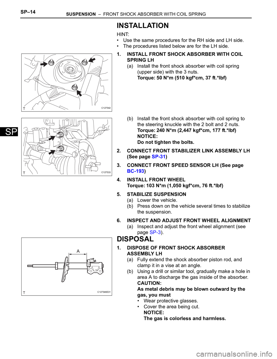
1. INSTALL FRONT SHOCK ABSORBER WITH COIL
SPRING LH
(a) Install the front shock absorber with coil spring
(upper side) with the 3 nuts.
Torque: 50 N*m (510 kgf*cm, 37 ft.*lbf)
(b) Install the front shock absorber with coil spring to
the steering knuckle with the 2 bolt and 2 nuts.
Torque: 240 N*m (2,447 kgf*cm, 177 ft.*lbf)
NOTICE:
Do not tighten the bolts.
2. CONNECT FRONT STABILIZER LINK ASSEMBLY LH
(See page SP-31)
3. CONNECT FRONT SPEED SENSOR LH (See page
BC-193)
4. INSTALL FRONT WHEEL
Torque: 103 N*m (1,050 kgf*cm, 76 ft.*lbf)
5. STABILIZE SUSPENSION
(a) Lower the vehicle.
(b) Press down on the vehicle several times to stabilize
the suspension.
6. INSPECT AND ADJUST FRONT WHEEL ALIGNMENT
(a) Inspect and adjust the front wheel alignment (see
page SP-3).
DISPOSAL
1. DISPOSE OF FRONT SHOCK ABSORBER
ASSEMBLY LH
(a) Fully extend the shock absorber piston rod, and
clamp it in a vise at an angle.
(b) Using a drill or similar tool, gradually make a hole in
area A to discharge the gas inside of the absorber.
CAUTION:
As metal debris may be blown outward by the
gas, you must
• Wear protective glasses.
• Cover the area being cut.
NOTICE:
The gas is colorless and harmless.
C127542
C127533
C127546E01
Page 1465 of 2000
SP–20SUSPENSION – FRONT SHOCK ABSORBER WITH COIL SPRING (for Sport Package)
SP
INSTALLATION
HINT:
• Use the same procedures for the RH side and LH side.
• The procedures listed below are for the LH side.
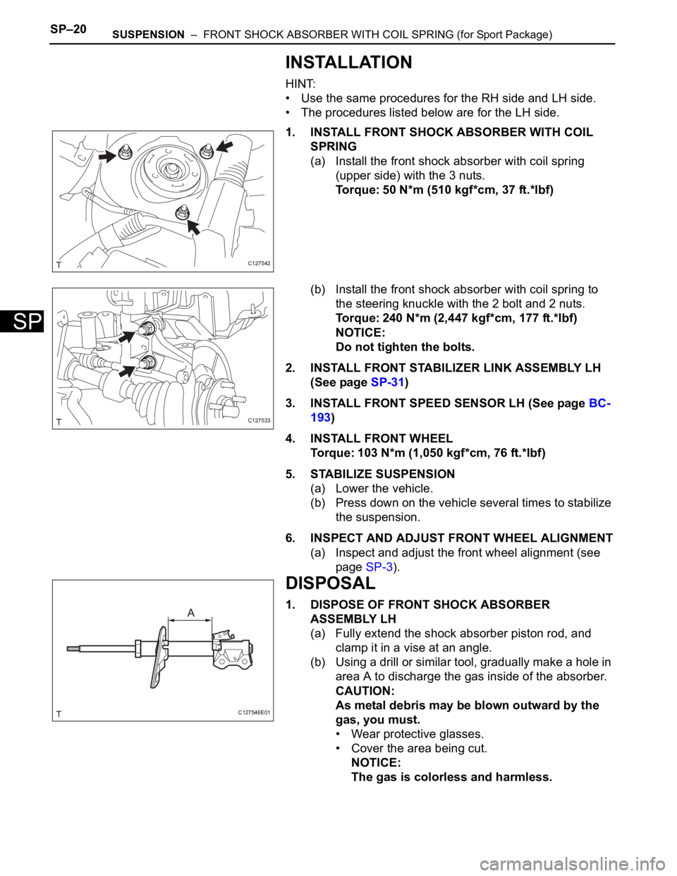
1. INSTALL FRONT SHOCK ABSORBER WITH COIL
SPRING
(a) Install the front shock absorber with coil spring
(upper side) with the 3 nuts.
Torque: 50 N*m (510 kgf*cm, 37 ft.*lbf)
(b) Install the front shock absorber with coil spring to
the steering knuckle with the 2 bolt and 2 nuts.
Torque: 240 N*m (2,447 kgf*cm, 177 ft.*lbf)
NOTICE:
Do not tighten the bolts.
2. INSTALL FRONT STABILIZER LINK ASSEMBLY LH
(See page SP-31)
3. INSTALL FRONT SPEED SENSOR LH (See page BC-
193)
4. INSTALL FRONT WHEEL
Torque: 103 N*m (1,050 kgf*cm, 76 ft.*lbf)
5. STABILIZE SUSPENSION
(a) Lower the vehicle.
(b) Press down on the vehicle several times to stabilize
the suspension.
6. INSPECT AND ADJUST FRONT WHEEL ALIGNMENT
(a) Inspect and adjust the front wheel alignment (see
page SP-3).
DISPOSAL
1. DISPOSE OF FRONT SHOCK ABSORBER
ASSEMBLY LH
(a) Fully extend the shock absorber piston rod, and
clamp it in a vise at an angle.
(b) Using a drill or similar tool, gradually make a hole in
area A to discharge the gas inside of the absorber.
CAUTION:
As metal debris may be blown outward by the
gas, you must.
• Wear protective glasses.
• Cover the area being cut.
NOTICE:
The gas is colorless and harmless.
C127542
C127533
C127546E01
Page 1469 of 2000
SP–28SUSPENSION – FRONT LOWER BALL JOINT
SP
INSTALLATION
HINT:
• Use the same procedures for the RH side and LH side.
• The procedures listed below are for the LH side.
1. INSTALL FRONT LOWER BALL JOINT ASSEMBLY
LH
(a) Install the ball joint with the 2 bolts and nut to the
lower arm.
Torque: 92 N*m (938 kgf*cm, 68 ft.*lbf)
(b) Install the lower ball joint with the nut to the steering
knuckle.
Torque: 133 N*m (1,360 kgf*cm, 98 ft.*lbf)
(c) Install a new cotter pin.
If the holes for the cotter pin are not aligned, tighten
the nut further up to 60
.
2. INSTALL STEERING KNUCKLE WITH AXLE HUB
(See page AH-9)
3. CONNECT FRONT SUSPENSION LOWER NO. 1 ARM
SUB-ASSEMBLY LH (See page AH-10)
4. CONNECT TIE ROD END SUB-ASSEMBLY LH (See
page PS-45)
5. INSTALL FRONT DISC (See page BR-43)
6. INSTALL FRONT DISC BRAKE CYLINDER
ASSEMBLY LH (See page BR-46)
7. INSTALL FRONT AXLE HUB NUT (See page AH-10)
8. INSTALL FRONT SPEED SENSOR LH (See page BC-
193)
9. INSTALL FRONT WHEEL
Torque: 103 N*m (1,050 kgf*cm, 76 ft.*lbf)
10. INSPECT AND ADJUST FRONT WHEEL ALIGNMENT
(a) Inspect and adjust the front wheel alignment (see
page SP-3).
Page 1470 of 2000
SP–34SUSPENSION – REAR COIL SPRING
SP
INSTALLATION
HINT:
• Use the same procedures for the RH side and LH side.
• The procedures listed below are for the LH side.
1. INSTALL REAR COIL SPRING INSULATOR LOWER
LH
(a) Install the insulator lower to the suspension No. 2
arm.
2. REMOVE REAR COIL SPRING LH
(a) Install the coil spring to the suspension No. 2 arm.
3. INSTALL REAR COIL SPRING INSULATOR UPPER
LH
(a) Align the stopper part of the insulator upper with the
coil spring tip, and install the insulator upper.
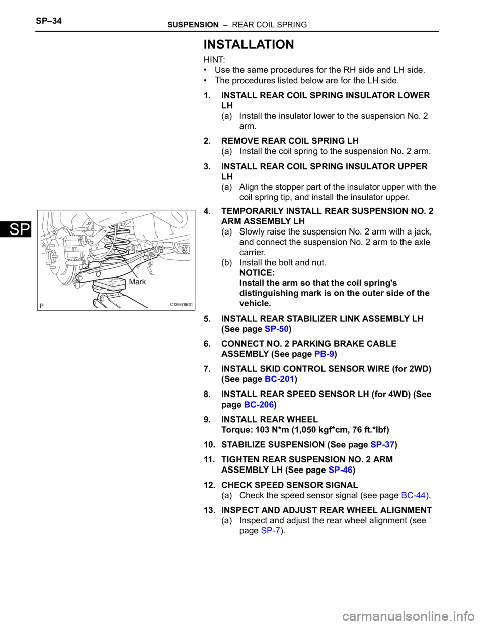
4. TEMPORARILY INSTALL REAR SUSPENSION NO. 2
ARM ASSEMBLY LH
(a) Slowly raise the suspension No. 2 arm with a jack,
and connect the suspension No. 2 arm to the axle
carrier.
(b) Install the bolt and nut.
NOTICE:
Install the arm so that the coil spring's
distinguishing mark is on the outer side of the
vehicle.
5. INSTALL REAR STABILIZER LINK ASSEMBLY LH
(See page SP-50)
6. CONNECT NO. 2 PARKING BRAKE CABLE
ASSEMBLY (See page PB-9)
7. INSTALL SKID CONTROL SENSOR WIRE (for 2WD)
(See page BC-201)
8. INSTALL REAR SPEED SENSOR LH (for 4WD) (See
page BC-206)
9. INSTALL REAR WHEEL
Torque: 103 N*m (1,050 kgf*cm, 76 ft.*lbf)
10. STABILIZE SUSPENSION (See page SP-37)
11. TIGHTEN REAR SUSPENSION NO. 2 ARM
ASSEMBLY LH (See page SP-46)
12. CHECK SPEED SENSOR SIGNAL
(a) Check the speed sensor signal (see page BC-44).
13. INSPECT AND ADJUST REAR WHEEL ALIGNMENT
(a) Inspect and adjust the rear wheel alignment (see
page SP-7).
C129676E01