2006 TOYOTA RAV4 sensor
[x] Cancel search: sensorPage 1361 of 2000
GF1A TRANSFER – ACTIVE TORQUE CONTROL 4WD SYSTEMTF–33
TF
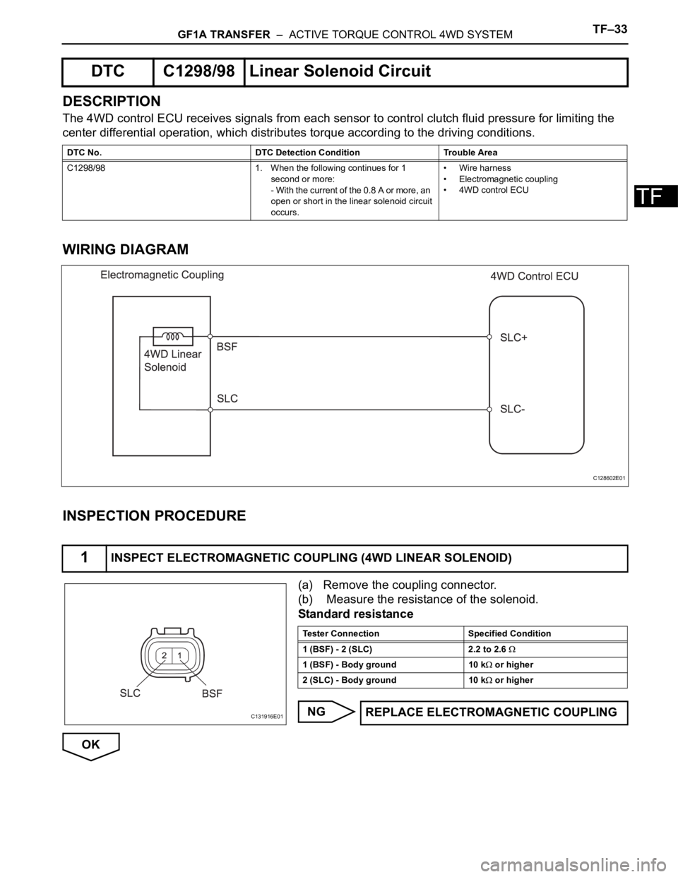
DESCRIPTION
The 4WD control ECU receives signals from each sensor to control clutch fluid pressure for limiting the
center differential operation, which distributes torque according to the driving conditions.
WIRING DIAGRAM
INSPECTION PROCEDURE
(a) Remove the coupling connector.
(b) Measure the resistance of the solenoid.
Standard resistance
NG
OK
DTC C1298/98 Linear Solenoid Circuit
DTC No. DTC Detection Condition Trouble Area
C1298/98 1. When the following continues for 1
second or more:
- With the current of the 0.8 A or more, an
open or short in the linear solenoid circuit
occurs.• Wire harness
• Electromagnetic coupling
• 4WD control ECU
1INSPECT ELECTROMAGNETIC COUPLING (4WD LINEAR SOLENOID)
C128602E01
C131916E01
Tester Connection Specified Condition
1 (BSF) - 2 (SLC) 2.2 to 2.6
1 (BSF) - Body ground 10 k or higher
2 (SLC) - Body ground 10 k
or higher
REPLACE ELECTROMAGNETIC COUPLING
Page 1363 of 2000
DRIVE SHAFT – FRONT DRIVE SHAFT ASSEMBLY (for 2WD)DS–7
DS
REMOVAL
(2005/11-2006/01)
1. REMOVE FRONT WHEEL
2. DRAIN AUTOMATIC TRANSAXLE FLUID
(a) Drain the automatic transaxle fluid for U140F (see
page AX-147).
(b) Drain the automatic transaxle fluid for U241E (see
page AX-146).
3. REMOVE FRONT AXLE HUB NUT (See page AH-6)
4. DISCONNECT FRONT SPEED SENSOR LH
(a) Disconnect the speed sensor (see page BC-191).
5. DISCONNECT FRONT SPEED SENSOR RH
HINT:
Use the same procedures described for the LH side.
6. DISCONNECT FRONT DISC BRAKE CYLINDER
ASSEMBLY LH (See page BR-40)
7. DISCONNECT FRONT DISC BRAKE CALIPER
ASSEMBLY RH
HINT:
Use the same procedures described for the LH side.
8. REMOVE FRONT STABILIZER LINK ASSEMBLY LH
(See page SP-30)
9. REMOVE FRONT STABILIZER LINK ASSEMBLY RH
HINT:
Use the same procedures described for the LH side.
10. DISCONNECT FRONT SUSPENSION LOWER NO. 1
ARM SUB-ASSEMBLY LH (See page AH-7)
11. DISCONNECT FRONT SUSPENSION LOWER NO. 1
ARM SUB-ASSEMBLY RH
HINT:
Use the same procedures described for the LH side.
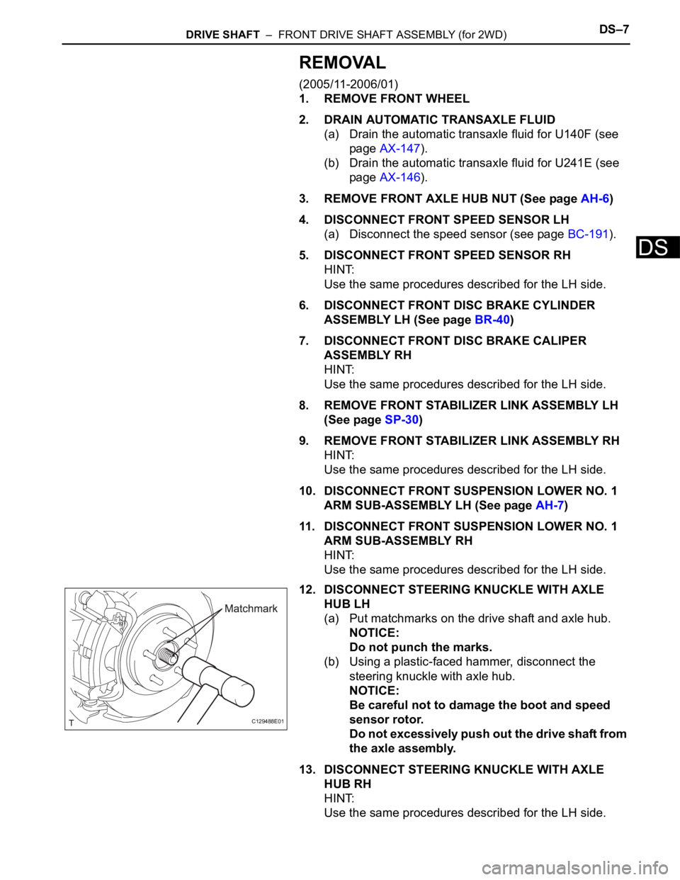
12. DISCONNECT STEERING KNUCKLE WITH AXLE
HUB LH
(a) Put matchmarks on the drive shaft and axle hub.
NOTICE:
Do not punch the marks.
(b) Using a plastic-faced hammer, disconnect the
steering knuckle with axle hub.
NOTICE:
Be careful not to damage the boot and speed
sensor rotor.
Do not excessively push out the drive shaft from
the axle assembly.
13. DISCONNECT STEERING KNUCKLE WITH AXLE
HUB RH
HINT:
Use the same procedures described for the LH side.
C129488E01
Page 1365 of 2000
DRIVE SHAFT – FRONT DRIVE SHAFT ASSEMBLY (for 2WD)DS–9
DS
REMOVAL
(2006/01- )
1. REMOVE FRONT WHEEL
2. DRAIN AUTOMATIC TRANSAXLE FLUID
(a) Drain the automatic transaxle fluid for U140F (see
page AX-147).
(b) Drain the automatic transaxle fluid for U241E (see
page AX-146).
(c) Drain the automatic transaxle fluid for U151E (see
page AX-172).
3. REMOVE FRONT AXLE HUB NUT (See page AH-8)
4. DISCONNECT FRONT SPEED SENSOR LH
(a) Disconnect the speed sensor (see page BC-191).
5. REMOVE FRONT SPEED SENSOR RH
HINT:
Use the same procedures described for the LH side.
6. DISCONNECT FRONT DISC BRAKE CYLINDER
ASSEMBLY LH (See page BR-40)
7. DISCONNECT FRONT DISC BRAKE CYLINDER
ASSEMBLY RH
HINT:
Use the same procedures described for the LH side.
8. REMOVE FRONT STABILIZER LINK ASSEMBLY LH
(See page SP-30)
9. REMOVE FRONT STABILIZER LINK ASSEMBLY RH
HINT:
Use the same procedures described for the LH side.
10. DISCONNECT FRONT SUSPENSION LOWER NO. 1
ARM SUB-ASSEMBLY LH (See page SP-21)
11. DISCONNECT FRONT SUSPENSION LOWER NO. 1
ARM SUB-ASSEMBLY RH
HINT:
Use the same procedures described for the LH side.
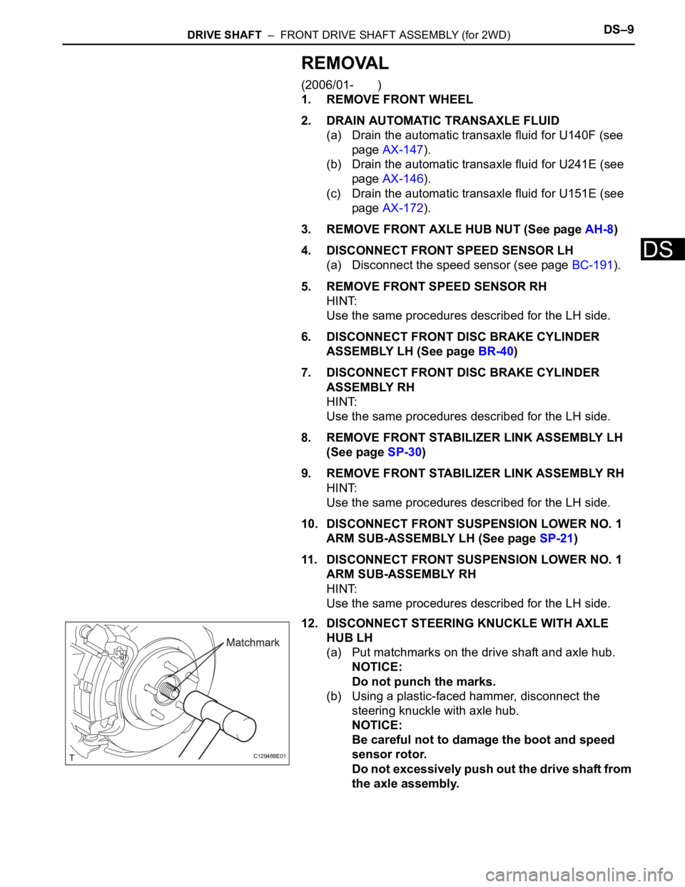
12. DISCONNECT STEERING KNUCKLE WITH AXLE
HUB LH
(a) Put matchmarks on the drive shaft and axle hub.
NOTICE:
Do not punch the marks.
(b) Using a plastic-faced hammer, disconnect the
steering knuckle with axle hub.
NOTICE:
Be careful not to damage the boot and speed
sensor rotor.
Do not excessively push out the drive shaft from
the axle assembly.
C129488E01
Page 1388 of 2000
DS–32DRIVE SHAFT – FRONT DRIVE SHAFT ASSEMBLY (for 2WD)
DS
INSTALLATION
(2005/11-2006/01)
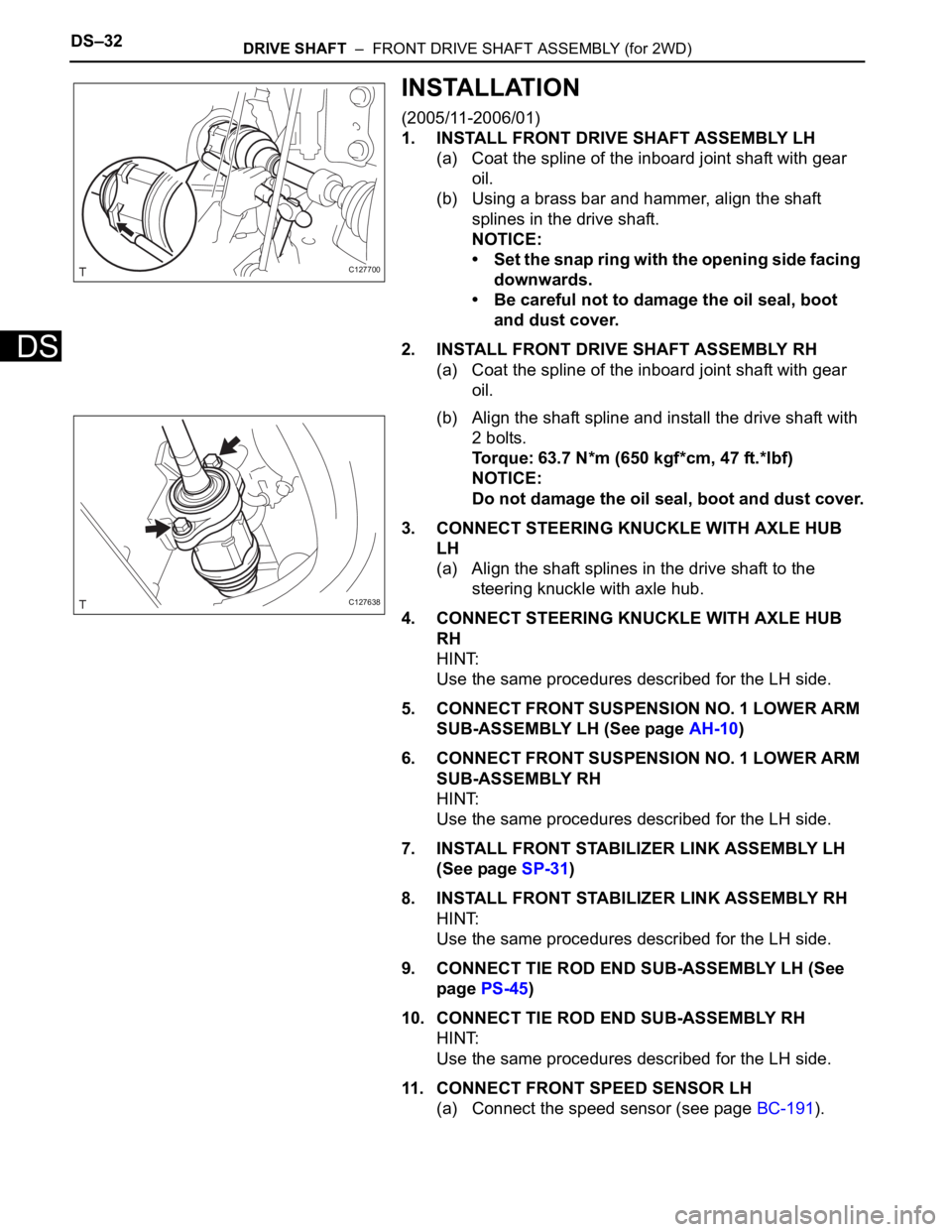
1. INSTALL FRONT DRIVE SHAFT ASSEMBLY LH
(a) Coat the spline of the inboard joint shaft with gear
oil.
(b) Using a brass bar and hammer, align the shaft
splines in the drive shaft.
NOTICE:
• Set the snap ring with the opening side facing
downwards.
• Be careful not to damage the oil seal, boot
and dust cover.
2. INSTALL FRONT DRIVE SHAFT ASSEMBLY RH
(a) Coat the spline of the inboard joint shaft with gear
oil.
(b) Align the shaft spline and install the drive shaft with
2 bolts.
Torque: 63.7 N*m (650 kgf*cm, 47 ft.*lbf)
NOTICE:
Do not damage the oil seal, boot and dust cover.
3. CONNECT STEERING KNUCKLE WITH AXLE HUB
LH
(a) Align the shaft splines in the drive shaft to the
steering knuckle with axle hub.
4. CONNECT STEERING KNUCKLE WITH AXLE HUB
RH
HINT:
Use the same procedures described for the LH side.
5. CONNECT FRONT SUSPENSION NO. 1 LOWER ARM
SUB-ASSEMBLY LH (See page AH-10)
6. CONNECT FRONT SUSPENSION NO. 1 LOWER ARM
SUB-ASSEMBLY RH
HINT:
Use the same procedures described for the LH side.
7. INSTALL FRONT STABILIZER LINK ASSEMBLY LH
(See page SP-31)
8. INSTALL FRONT STABILIZER LINK ASSEMBLY RH
HINT:
Use the same procedures described for the LH side.
9. CONNECT TIE ROD END SUB-ASSEMBLY LH (See
page PS-45)
10. CONNECT TIE ROD END SUB-ASSEMBLY RH
HINT:
Use the same procedures described for the LH side.
11. CONNECT FRONT SPEED SENSOR LH
(a) Connect the speed sensor (see page BC-191).
C127700
C127638
Page 1389 of 2000
DRIVE SHAFT – FRONT DRIVE SHAFT ASSEMBLY (for 2WD)DS–33
DS
12. CONNECT FRONT SPEED SENSOR RH
HINT:
Use the same procedures described for the LH side.
13. INSTALL FRONT AXLE HUB NUT (See page AH-10)
14. INSTALL FRONT WHEEL
Torque: 103 N*m (1,050 kgf*cm, 76 ft.*lbf)
15. ADD AUTOMATIC TRANSAXLE FLUID
(a) Add automatic transaxle fluid for U140F (see page
AX-152).
(b) Add automatic transaxle fluid for U241E (see page
AX-151).
16. CHECK FOR AUTOMATIC TRANSAXLE OIL
LEAKAGE
17. INSPECT AND ADJUST FRONT WHEEL ALIGNMENT
(a) Inspect and adjust the front wheel alignment (see
page SP-3).
INSTALLATION
(2006/01- )
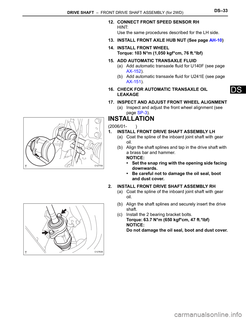
1. INSTALL FRONT DRIVE SHAFT ASSEMBLY LH
(a) Coat the spline of the inboard joint shaft with gear
oil.
(b) Align the shaft splines and tap in the drive shaft with
a brass bar and hammer.
NOTICE:
• Set the snap ring with the opening side facing
downwards.
• Be careful not to damage the oil seal, boot
and dust cover.
2. INSTALL FRONT DRIVE SHAFT ASSEMBLY RH
(a) Coat the spline of the inboard joint shaft with gear
oil.
(b) Align the shaft splines and securely insert the drive
shaft.
(c) Install the 2 bearing bracket bolts.
Torque: 63.7 N*m (650 kgf*cm, 47 ft.*lbf)
NOTICE:
Do not damage the oil seal, boot and dust cover.
C127700
C127638
Page 1390 of 2000
DS–34DRIVE SHAFT – FRONT DRIVE SHAFT ASSEMBLY (for 2WD)
DS
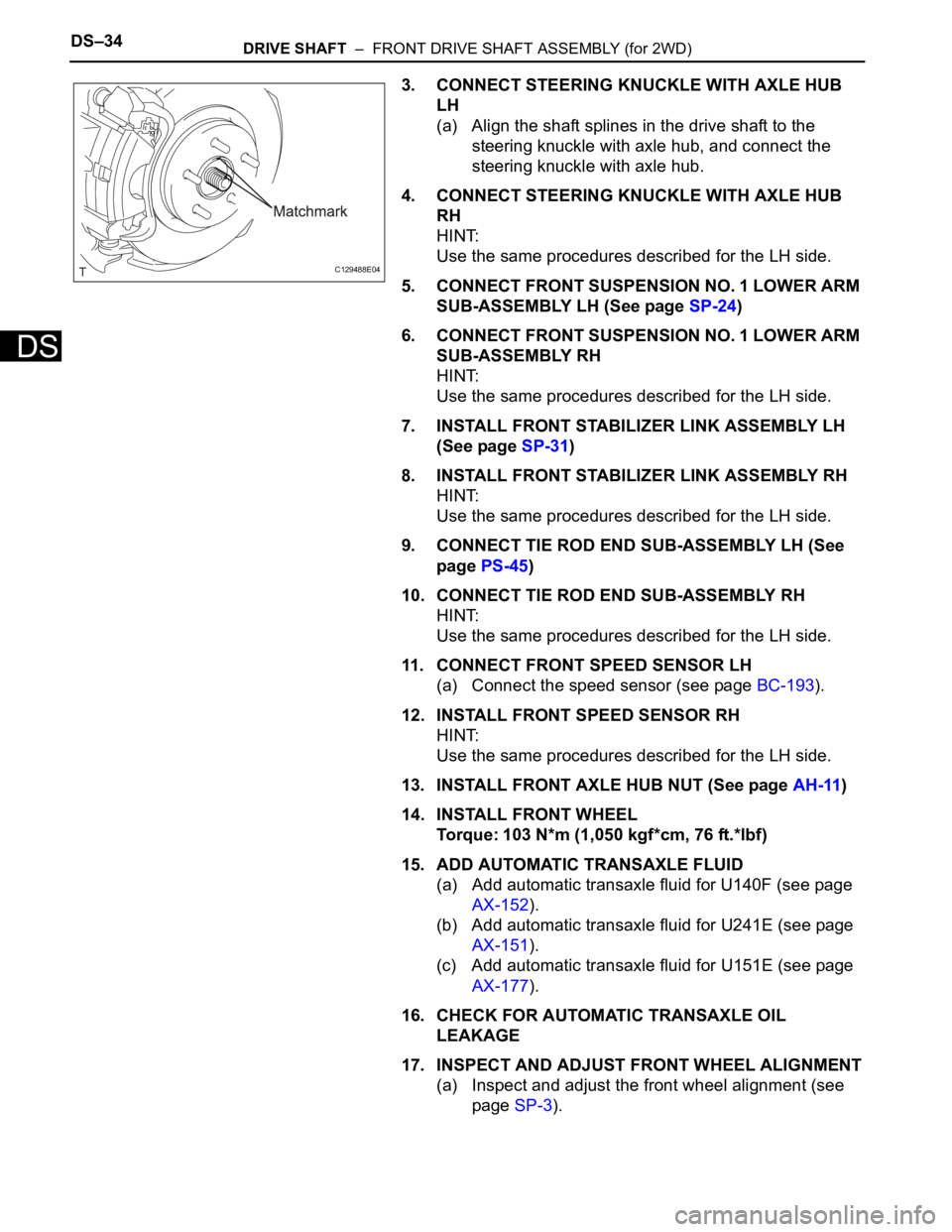
3. CONNECT STEERING KNUCKLE WITH AXLE HUB
LH
(a) Align the shaft splines in the drive shaft to the
steering knuckle with axle hub, and connect the
steering knuckle with axle hub.
4. CONNECT STEERING KNUCKLE WITH AXLE HUB
RH
HINT:
Use the same procedures described for the LH side.
5. CONNECT FRONT SUSPENSION NO. 1 LOWER ARM
SUB-ASSEMBLY LH (See page SP-24)
6. CONNECT FRONT SUSPENSION NO. 1 LOWER ARM
SUB-ASSEMBLY RH
HINT:
Use the same procedures described for the LH side.
7. INSTALL FRONT STABILIZER LINK ASSEMBLY LH
(See page SP-31)
8. INSTALL FRONT STABILIZER LINK ASSEMBLY RH
HINT:
Use the same procedures described for the LH side.
9. CONNECT TIE ROD END SUB-ASSEMBLY LH (See
page PS-45)
10. CONNECT TIE ROD END SUB-ASSEMBLY RH
HINT:
Use the same procedures described for the LH side.
11. CONNECT FRONT SPEED SENSOR LH
(a) Connect the speed sensor (see page BC-193).
12. INSTALL FRONT SPEED SENSOR RH
HINT:
Use the same procedures described for the LH side.
13. INSTALL FRONT AXLE HUB NUT (See page AH-11)
14. INSTALL FRONT WHEEL
Torque: 103 N*m (1,050 kgf*cm, 76 ft.*lbf)
15. ADD AUTOMATIC TRANSAXLE FLUID
(a) Add automatic transaxle fluid for U140F (see page
AX-152).
(b) Add automatic transaxle fluid for U241E (see page
AX-151).
(c) Add automatic transaxle fluid for U151E (see page
AX-177).
16. CHECK FOR AUTOMATIC TRANSAXLE OIL
LEAKAGE
17. INSPECT AND ADJUST FRONT WHEEL ALIGNMENT
(a) Inspect and adjust the front wheel alignment (see
page SP-3).
C129488E04
Page 1394 of 2000
DS–40DRIVE SHAFT – FRONT DRIVE SHAFT ASSEMBLY (for 4WD)
DS
REMOVAL
(2005/11-2006/01)
1. REMOVE FRONT WHEEL
2. DRAIN AUTOMATIC TRANSAXLE FLUID
(a) Drain the automatic transaxle fluid for U140F (see
page AX-147).
(b) Drain the automatic transaxle fluid for U241E (see
page AX-146).
3. REMOVE FRONT AXLE HUB NUT (See page AH-6)
4. DISCONNECT FRONT SPEED SENSOR LH (See page
BC-191)
5. DISCONNECT FRONT SPEED SENSOR RH
HINT:
Use the same procedures described for the LH side.
6. DISCONNECT FRONT DISC BRAKE CYLINDER
ASSEMBLY LH (See page BR-40)
7. DISCONNECT FRONT DISC BRAKE CYLINDER
ASSEMBLY RH
HINT:
Use the same procedures described for the LH side.
8. DISCONNECT FRONT STABILIZER LINK ASSEMBLY
LH (See page SP-9)
9. DISCONNECT FRONT STABILIZER LINK ASSEMBLY
RH
HINT:
Use the same procedures described for the LH side.
10. DISCONNECT FRONT SUSPENSION LOWER NO. 1
ARM SUB-ASSEMBLY LH (See page AH-7)
11. DISCONNECT FRONT SUSPENSION LOWER NO. 1
ARM SUB-ASSEMBLY RH
HINT:
Use the same procedures described for the LH side.
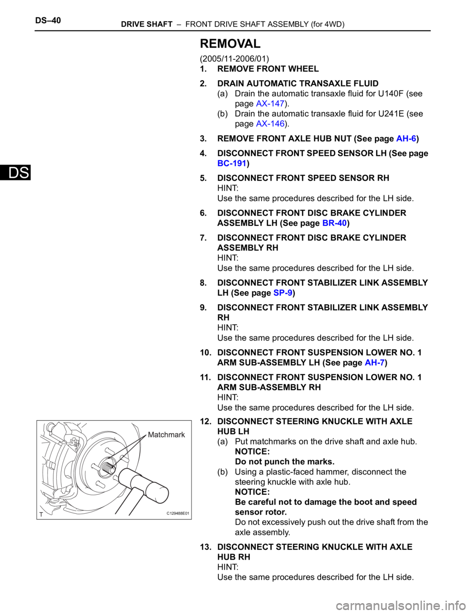
12. DISCONNECT STEERING KNUCKLE WITH AXLE
HUB LH
(a) Put matchmarks on the drive shaft and axle hub.
NOTICE:
Do not punch the marks.
(b) Using a plastic-faced hammer, disconnect the
steering knuckle with axle hub.
NOTICE:
Be careful not to damage the boot and speed
sensor rotor.
Do not excessively push out the drive shaft from the
axle assembly.
13. DISCONNECT STEERING KNUCKLE WITH AXLE
HUB RH
HINT:
Use the same procedures described for the LH side.
C129488E01
Page 1396 of 2000
DS–42DRIVE SHAFT – FRONT DRIVE SHAFT ASSEMBLY (for 4WD)
DS
REMOVAL
(2006/01- )
1. REMOVE FRONT WHEEL
2. DRAIN AUTOMATIC TRANSAXLE FLUID
(a) Drain the automatic transaxle fluid for U140F (see
page AX-147).
(b) Drain the automatic transaxle fluid for U241E (see
page AX-146).
(c) Drain the automatic transaxle fluid for U151F (see
page AX-173).
3. REMOVE FRONT AXLE HUB NUT (See page AH-8)
4. DISCONNECT FRONT SPEED SENSOR LH (See page
BC-191)
5. DISCONNECT FRONT SPEED SENSOR RH
HINT:
Use the same procedures described for the LH side.
6. DISCONNECT FRONT DISC BRAKE CYLINDER
ASSEMBLY LH (See page BR-40)
7. DISCONNECT FRONT DISC BRAKE CYLINDER
ASSEMBLY RH
HINT:
Use the same procedures described for the LH side.
8. DISCONNECT FRONT STABILIZER LINK ASSEMBLY
LH (See page SP-30)
9. DISCONNECT FRONT STABILIZER LINK ASSEMBLY
RH
10. DISCONNECT FRONT SUSPENSION LOWER NO. 1
ARM SUB-ASSEMBLY LH (See page SP-22)
11. DISCONNECT FRONT SUSPENSION LOWER NO. 1
ARM SUB-ASSEMBLY RH
HINT:
Use the same procedures described for the LH side.
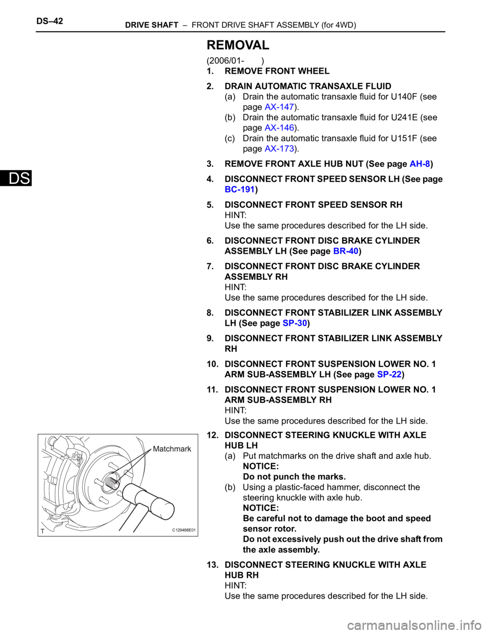
12. DISCONNECT STEERING KNUCKLE WITH AXLE
HUB LH
(a) Put matchmarks on the drive shaft and axle hub.
NOTICE:
Do not punch the marks.
(b) Using a plastic-faced hammer, disconnect the
steering knuckle with axle hub.
NOTICE:
Be careful not to damage the boot and speed
sensor rotor.
Do not excessively push out the drive shaft from
the axle assembly.
13. DISCONNECT STEERING KNUCKLE WITH AXLE
HUB RH
HINT:
Use the same procedures described for the LH side.
C129488E01