Page 1170 of 2000
AX–192U151F AUTOMATIC TRANSAXLE – AUTOMATIC TRANSAXLE UNIT
AX
10. INSPECT TRANSMISSION OIL CLEANER MAGNET
(a) Remove the magnets and use them to collect any
steel chips. Examine the chips and particles in the
pan and on the magnet to determine what type of
wear has occurred in the transaxle.
Result:
Steel (magnetic):
Wear of the bearing, gear and plate
Brass (non-magnetic):
Wear of the bush
11. REMOVE VALVE BODY OIL STRAINER ASSEMBLY
(a) Remove the 3 bolts and oil strainer.
(b) Remove the O-ring from the oil strainer.
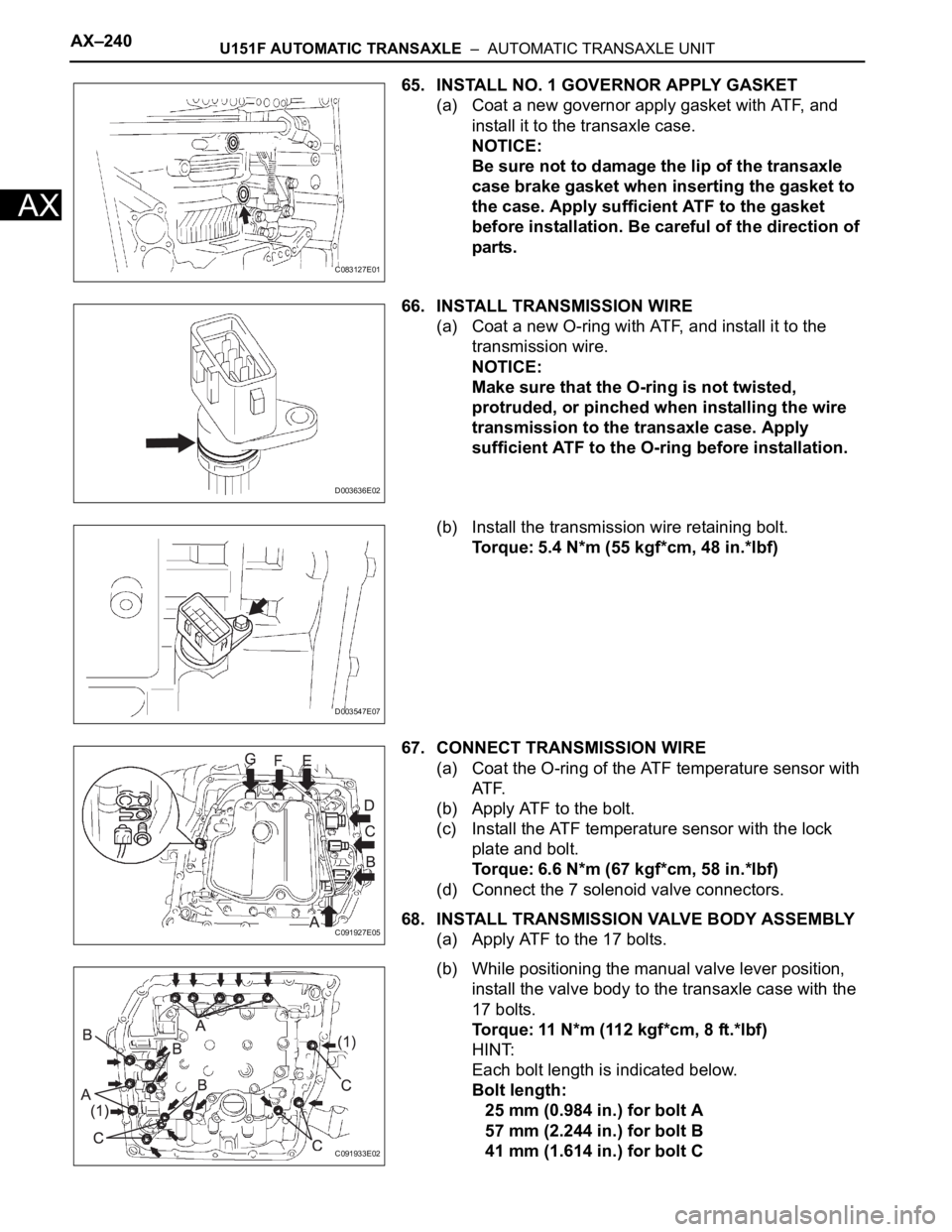
12. REMOVE TRANSMISSION WIRE
(a) Remove the 7 connectors from the shift solenoid
valves.
(b) Remove the bolt, lock plate and temperature
sensor.
(c) Remove the bolt and transmission wire from the
transaxle case.
AT00103E01
C091931E02
C091932E02
C134996E01
D003547E07
Page 1218 of 2000

AX–240U151F AUTOMATIC TRANSAXLE – AUTOMATIC TRANSAXLE UNIT
AX
65. INSTALL NO. 1 GOVERNOR APPLY GASKET
(a) Coat a new governor apply gasket with ATF, and
install it to the transaxle case.
NOTICE:
Be sure not to damage the lip of the transaxle
case brake gasket when inserting the gasket to
the case. Apply sufficient ATF to the gasket
before installation. Be careful of the direction of
parts.
66. INSTALL TRANSMISSION WIRE
(a) Coat a new O-ring with ATF, and install it to the
transmission wire.
NOTICE:
Make sure that the O-ring is not twisted,
protruded, or pinched when installing the wire
transmission to the transaxle case. Apply
sufficient ATF to the O-ring before installation.
(b) Install the transmission wire retaining bolt.
Torque: 5.4 N*m (55 kgf*cm, 48 in.*lbf)
67. CONNECT TRANSMISSION WIRE
(a) Coat the O-ring of the ATF temperature sensor with
AT F.
(b) Apply ATF to the bolt.
(c) Install the ATF temperature sensor with the lock
plate and bolt.
Torque: 6.6 N*m (67 kgf*cm, 58 in.*lbf)
(d) Connect the 7 solenoid valve connectors.
68. INSTALL TRANSMISSION VALVE BODY ASSEMBLY
(a) Apply ATF to the 17 bolts.
(b) While positioning the manual valve lever position,
install the valve body to the transaxle case with the
17 bolts.
Torque: 11 N*m (112 kgf*cm, 8 ft.*lbf)
HINT:
Each bolt length is indicated below.
Bolt length:
25 mm (0.984 in.) for bolt A
57 mm (2.244 in.) for bolt B
41 mm (1.614 in.) for bolt C
C083127E01
D003636E02
D003547E07
C091927E05
C091933E02
Page 1220 of 2000

AX–242U151F AUTOMATIC TRANSAXLE – AUTOMATIC TRANSAXLE UNIT
AX
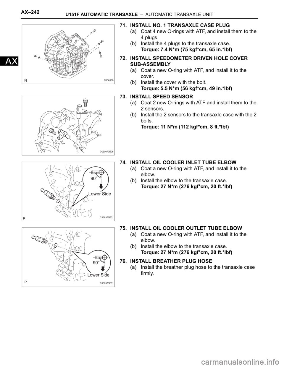
71. INSTALL NO. 1 TRANSAXLE CASE PLUG
(a) Coat 4 new O-rings with ATF, and install them to the
4 plugs.
(b) Install the 4 plugs to the transaxle case.
Torque: 7.4 N*m (75 kgf*cm, 65 in.*lbf)
72. INSTALL SPEEDOMETER DRIVEN HOLE COVER
SUB-ASSEMBLY
(a) Coat a new O-ring with ATF, and install it to the
cover.
(b) Install the cover with the bolt.
Torque: 5.5 N*m (56 kgf*cm, 49 in.*lbf)
73. INSTALL SPEED SENSOR
(a) Coat 2 new O-rings with ATF and install them to the
2 sensors.
(b) Install the 2 sensors to the transaxle case with the 2
bolts.
Torque: 11 N*m (112 kgf*cm, 8 ft.*lbf)
74. INSTALL OIL COOLER INLET TUBE ELBOW
(a) Coat a new O-ring with ATF, and install it to the
elbow.
(b) Install the elbow to the transaxle case.
Torque: 27 N*m (276 kgf*cm, 20 ft.*lbf)
75. INSTALL OIL COOLER OUTLET TUBE ELBOW
(a) Coat a new O-ring with ATF, and install it to the
elbow.
(b) Install the elbow to the transaxle case.
Torque: 27 N*m (276 kgf*cm, 20 ft.*lbf)
76. INSTALL BREATHER PLUG HOSE
(a) Install the breather plug hose to the transaxle case
firmly.
C136368
D030672E06
C136372E01
C136373E01
Page 1249 of 2000
U241E AUTOMATIC TRANSAXLE – AUTOMATIC TRANSAXLE SYSTEMAX–25
AX
HINT:
*: Drive at such a speed in the uppermost gear to engage
lock-up. The vehicle can be driven at a speed lower than the
speed shown in the above diagram under the lock-up
condition.
NOTICE:
It is necessary to drive the vehicle for approximately 30
minutes to detect DTC P0711 (Transmission fluid
temperature sensor "A" performance).
C115866E05
Page 1250 of 2000

AX–26U241E AUTOMATIC TRANSAXLE – AUTOMATIC TRANSAXLE SYSTEM
AX
PROBLEM SYMPTOMS TABLE
HINT:
• Use the table below to help determine the cause of the
problem symptom. The potential causes of the symptoms
are listed in order of probability in the "Suspected area"
column of the table. Check each symptom by checking the
suspected areas in the order they are listed. Replace parts
as necessary.
• The Matrix Chart is divided into 2 chapters. When
troubleshooting, check Chapter 1 first. If instructions are
given in Chapter 1 to proceed to 2, proceed as instructed.
• If the instruction "Proceed to next circuit inspection shown
in problem symptoms table" is given in the flowchart for
each circuit, proceed to the next suspected area in the
table.
• If the problem still occurs even though there are no
malfunctions in any of the circuits, check the ECM and
replace it if necessary.
CHAPTER 1: ELECTRICAL CIRCUIT MATRIX CHART
HINT:
*: When the circuit is defective, a DTC may be output.
CHAPTER 2: ON-VEHICLE REPAIR AND OFF-VEHICLE REPAIR
Symptom Suspected area See page
No up-shift (1st -> 2nd) ECMIN-37
No up-shift (2nd -> 3rd) ECMIN-37
No up-shift (3rd -> O/D)1. Park/Neutral position switch circuit*AX-39
2. ECMIN-37
No down-shift (O/D -> 3rd) ECMIN-37
No down-shift (3rd -> 2nd) ECMIN-37
No down-shift (2nd -> 1st) ECMIN-37
No lock-up or no lock-up off ECMIN-37
Shift point too high or too low ECMIN-37
Up-shift to O/D from 3rd while shift lever is on 31. Park/Neutral position switch circuit*AX-39
2. ECMIN-37
Up-shift to O/D from 3rd while engine is cold1. Engine coolant temp. sensor circuit*ES-51
2. ECMIN-37
Harsh engagement (N -> D) ECMIN-37
Harsh engagement (lock-up) ECMIN-37
Harsh engagement (any driving position) ECMIN-37
Poor acceleration ECMIN-37
Engine stalls when starting off or stopping ECMIN-37
Malfunction in shifting1. Park/Neutral position switch circuit*AX-39
2. ECMIN-37
Symptom Suspected area See page
Vehicle does not move in all positions other than P and
N1. Manual valveAX-154
2. Primary regulator valveAX-154
3. Front and rear planetary gearAX-154
4. U/D planetary gearAX-154
5. F2 U/D one-way clutchAX-154
6. C1 forward clutchAX-154
7. B3 U/D brakeAX-154
Page 1254 of 2000

AX–30U241E AUTOMATIC TRANSAXLE – AUTOMATIC TRANSAXLE SYSTEM
AX
3 (A9-26) - E1 (B30-104) P - BR 3 shift position switch
signalIgnition switch ON and
transfer shift lever on 310 to 14 V
3 (A9-26) - E1 (B30-104) P - BR 3 shift position switch
signalIgnition switch ON and
transfer shift lever not on 3Below 1 V
2 (B30-55) - E1 (B30-104) P - BR 2 shift position switch
signalIgnition switch ON and
transfer shift lever on 2
and L10 to 14 V
2 (B30-55) - E1 (B30-104) P - BR 2 shift position switch
signalIgnition switch ON and
transfer shift lever not on 2
and LBelow 1 V
L (B30-74) - E1 (B30-104) LG - BR L shift position switch
signalIgnition switch ON and
transfer shift lever on L10 to 14 V
L (B30-74) - E1 (B30-104) LG - BR L shift position switch
signalIgnition switch ON and
transfer shift lever not on LBelow 1 V
STP (A9-36) - E1 (B30-
104)L - BR Stop light switch signal Brake pedal is depressed Between 10 V and 14 V
STP (A9-36) - E1 (B30-
104)L - BR Stop light switch signal Brake pedal is released Below 1 V
SL1+ (B30-57) - SL1-
(B30-77)V - P SL1 solenoid signal Engine idle speed Pulse generation
(see waveform 1)
SL1+ (B30-57) - SL1-
(B30-77)V - P SL1 solenoid signal Ignition switch ON Pulse generation
(see waveform 1)
SL1+ (B30-57) - SL1-
(B30-77)V - P SL1 solenoid signal 1st gear Pulse generation
(see waveform 1)
SL1+ (B30-57) - SL1-
(B30-77)V - P SL1 solenoid signal Not on 1st gear Below 1 V
SL2+ (B30-58) - SL2-
(B30-59)Y - L SL2 solenoid signal Engine idle speed Pulse generation
(see waveform 2)
SL2+ (B30-58) - SL2-
(B30-59)Y - L SL2 solenoid signal Ignition switch ON Pulse generation
(see waveform 2)
SL2+ (B30-58) - SL2-
(B30-59)Y - L SL2 solenoid signal 1st or 2nd gear Pulse generation
(see waveform 2)
SL2+ (B30-58) - SL2-
(B30-59)Y - L SL2 solenoid signal 3rd or O/D gear Below 1 V
DSL (B30-79) - E01 (B30-
45)G - BR DSL solenoid signal Vehicle speed 65 km/h (40
mph), lock-up (ON to OFF)Below 1 V
DSL (B30-79) - E01 (B30-
45)G - BR DSL solenoid signal Vehicle driving under lock-
up positionPulse generation
(see waveform 3)
SLT+ (B30-76) - SLT-
(B30-75)R - GR SLT solenoid signal Engine idle speed Pulse generation
(see waveform 4)
S4 (B30-78) - E01 (B30-
45)W - BR S4 solenoid signal Ignition switch ON Below 1 V
S4 (B30-78) - E01 (B30-
45)W - BR S4 solenoid signal O/D gear 10 to 14 V
S4 (B30-78) - E01 (B30-
45)W - BR S4 solenoid signal Not on O/D gear Below 1 V
THO1 (B30-72) - ETHO
(B30-95)LG- BR ATF temperature sensor
signalATF temperature: 115
C
(239F) or moreBelow 1.5 V
NT+ (B30-125) - NT- (B30-
124)W - R Speed sensor (NT) signal Vehicle speed 20 km/h (12
mph)Pulse generation
(see waveform 5)
NC+ (B30-101) - NC-
(B30-102)R - W Speed sensor (NC) signal Vehicle speed 30 km/h (19
mph): (3rd gear)
Engine speed 1,400 rpmPulse generation
(see waveform 6) Symbols (Terminal No.) Wiring Color Terminal Description ConditionSpecified Condition
Page 1268 of 2000

U241E AUTOMATIC TRANSAXLE – AUTOMATIC TRANSAXLE ASSEMBLYAX–151
AX
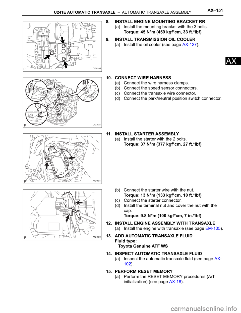
8. INSTALL ENGINE MOUNTING BRACKET RR
(a) Install the mounting bracket with the 3 bolts.
Torque: 45 N*m (459 kgf*cm, 33 ft.*lbf)
9. INSTALL TRANSMISSION OIL COOLER
(a) Install the oil cooler (see page AX-127).
10. CONNECT WIRE HARNESS
(a) Connect the wire harness clamps.
(b) Connect the speed sensor connectors.
(c) Connect the transaxle wire connector.
(d) Connect the park/neutral position switch connector.
11. INSTALL STARTER ASSEMBLY
(a) Install the starter with the 2 bolts.
Torque: 37 N*m (377 kgf*cm, 27 ft.*lbf)
(b) Connect the starter wire with the nut.
Torque: 13 N*m (133 kgf*cm, 10 ft.*lbf)
(c) Connect the starter connector.
(d) Install the terminal nut and cover the nut with the
cap.
Torque: 9.8 N*m (100 kgf*cm, 7 in.*lbf)
12. INSTALL ENGINE ASSEMBLY WITH TRANSAXLE
(a) Install the engine with transaxle (see page EM-105).
13. ADD AUTOMATIC TRANSAXLE FLUID
Fluid type:
Toyota Genuine ATF WS
14. INSPECT AUTOMATIC TRANSAXLE FLUID
(a) Inspect the automatic transaxle fluid (see page AX-
102).
15. PERFORM RESET MEMORY
(a) Perform the RESET MEMORY procedures (A/T
initialization) (see page AX-18).
C129395
C127821
A124921
A124920
Page 1270 of 2000
AX–166U241E AUTOMATIC TRANSAXLE – AUTOMATIC TRANSAXLE UNIT
AX
5. REMOVE OIL COOLER INLET TUBE UNION
(a) Remove the union.
(b) Remove the O-ring from the union.
6. REMOVE SPEED SENSOR
(a) Remove the 2 bolts and 2 speed sensors from the
transaxle.
(b) Remove the 2 O-rings from the sensors.
7. REMOVE NO. 1 TRANSAXLE CASE PLUG
(a) Remove the 4 plugs from the transaxle.
(b) Remove the 4 O-rings from the 4 plugs.
8. FIX AUTOMATIC TRANSAXLE ASSEMBLY
9. REMOVE AUTOMATIC TRANSAXLE OIL PAN SUB-
ASSEMBLY
(a) Remove the 18 bolts.
(b) Remove the oil pan and 3 magnets.
(c) Remove the gasket from the oil pan.
10. INSPECT AUTOMATIC TRANSAXLE OIL PAN SUB-
ASSEMBLY (See page AX-185)
C127450
D003900E01
C134982
D009176E01
D009177E01