2006 TOYOTA RAV4 stop start
[x] Cancel search: stop startPage 240 of 2000

CO–42AZ-FE COOLING – COOLING FAN SYSTEM
CO
ON-VEHICLE INSPECTION
HINT:
It is normal for the cooling fan to sometimes rotate when the
ignition switch is turned from ACC to ON.
1. CHECK COOLING FAN OPERATION AT LOW
TEMPERATURES (Below 94
C (201F))
(a) Turn the ignition switch ON with the A/C switch OFF.
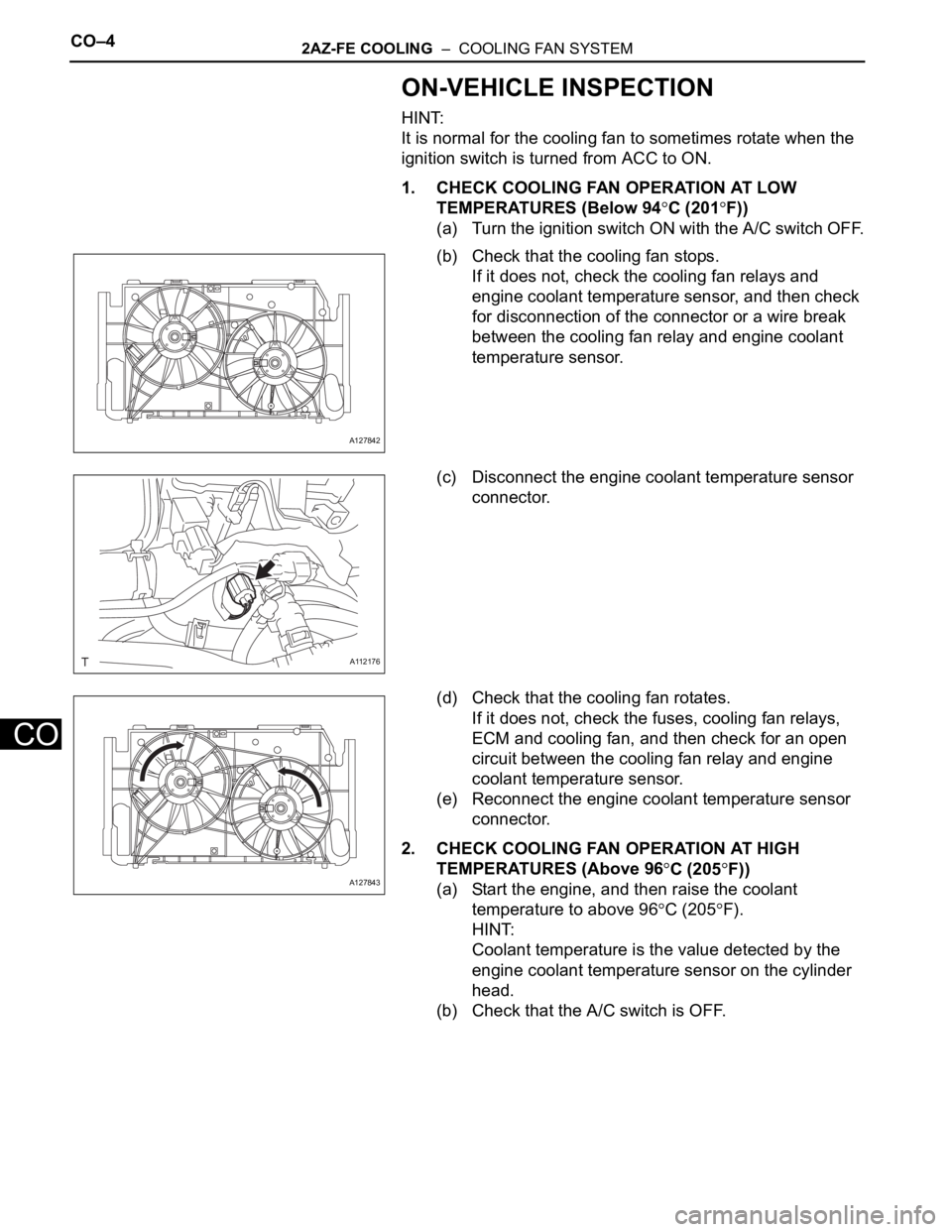
(b) Check that the cooling fan stops.
If it does not, check the cooling fan relays and
engine coolant temperature sensor, and then check
for disconnection of the connector or a wire break
between the cooling fan relay and engine coolant
temperature sensor.
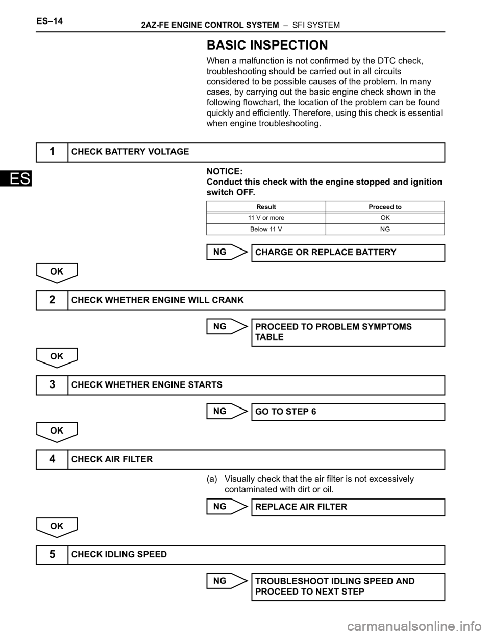
(c) Disconnect the engine coolant temperature sensor
connector.
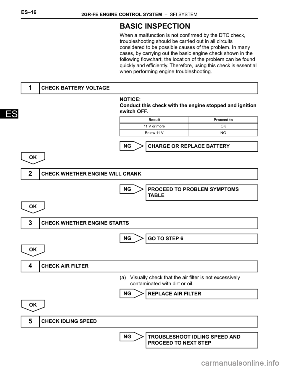
(d) Check that the cooling fan rotates.
If it does not, check the fuses, cooling fan relays,
ECM and cooling fan, and then check for an open
circuit between the cooling fan relay and engine
coolant temperature sensor.
(e) Reconnect the engine coolant temperature sensor
connector.
2. CHECK COOLING FAN OPERATION AT HIGH
TEMPERATURES (Above 96
C (205F))
(a) Start the engine, and then raise the coolant
temperature to above 96
C (205F).
HINT:
Coolant temperature is the value detected by the
engine coolant temperature sensor on the cylinder
head.
(b) Check that the A/C switch is OFF.
A127842
A112176
A127843
Page 468 of 2000

ES–142AZ-FE ENGINE CONTROL SYSTEM – SFI SYSTEM
ES
BASIC INSPECTION
When a malfunction is not confirmed by the DTC check,
troubleshooting should be carried out in all circuits
considered to be possible causes of the problem. In many
cases, by carrying out the basic engine check shown in the
following flowchart, the location of the problem can be found
quickly and efficiently. Therefore, using this check is essential
when engine troubleshooting.
NOTICE:
Conduct this check with the engine stopped and ignition
switch OFF.
NG
OK
NG
OK
NG
OK
(a) Visually check that the air filter is not excessively
contaminated with dirt or oil.
NG
OK
NG
1CHECK BATTERY VOLTAGE
Result Proceed to
11 V or more OK
Below 11 V NG
CHARGE OR REPLACE BATTERY
2CHECK WHETHER ENGINE WILL CRANK
PROCEED TO PROBLEM SYMPTOMS
TA B L E
3CHECK WHETHER ENGINE STARTS
GO TO STEP 6
4CHECK AIR FILTER
REPLACE AIR FILTER
5CHECK IDLING SPEED
TROUBLESHOOT IDLING SPEED AND
PROCEED TO NEXT STEP
Page 486 of 2000

ES–322AZ-FE ENGINE CONTROL SYSTEM – SFI SYSTEM
ES
VPA (A9-55) - EPA (A9-59) W - YAccelerator pedal position
sensor (for engine control)Ignition switch ON,
Accelerator pedal released0.5 to 1.1 V
Ignition switch ON,
Accelerator pedal fully depressed2.6 to 4.5 V
VPA2 (A9-56) - EPA2 (A9-60) R - OAccelerator pedal position
sensor (for sensor
malfunctioning detection)Ignition switch ON,
Accelerator pedal released1.2 to 2.0 V
Ignition switch ON,
Accelerator pedal fully depressed3.4 to 5.0 V
VCPA (A9-57) - EPA (A9-59) B - YPower source of
accelerator pedal position
sensor (for VPA)Ignition switch ON 4.5 to 5.5 V
VCP2 (A9-58) - EPA2 (A9-60) L - OPower source of
accelerator pedal position
sensor (for VPA2)Ignition switch ON 4.5 to 5.5 V
HA1A (B30-109) - E04 (B30-46) L - W-B A/F sensor heaterIdling Below 3.0 V
Ignition switch ON 9 to 14 V
A1A+ (B30-112) - E1 (B30-104) B -BR A/F sensor Ignition switch ON 3.3 V*
A1A- (B30-113) - E1 (B30-104) R - BR A/F sensor Ignition switch ON3.0 V*
HT1B (B30-47) - E03 (B30-86) R - W-BHeated oxygen sensor
heaterIdling Below 3.0 V
Ignition switch ON 9 to 14 V
OX1B (B30-64) - EX1B (B30-87) B - BR Heated oxygen sensorEngine speed maintained at 2,500
rpm for 2 minutes after warming up
sensorPulse generation (see
waveform 2)
#10 (B30-108) - E01 (B30-45)
#20 (B30-107) - E01 (B30-45)
#30 (B30-106) - E01 (B30-45)
#40 (B30-105) - E01 (B30-45)L - W-B
G - W-B
B - W-B
W - W-BInjectorIgnition switch ON 9 to 14 V
IdlingPulse generation (see
waveform 3)
KNK1 (B30-110) - EKNK (B30-
111 )B - W Knock sensorEngine speed maintained at 4,000
after warming up enginePulse generation (see
waveform 4)
G2+ (B30-99) - G2- (B30-98) L - Y Camshaft position sensor IdlingPulse generation (see
waveform 5)
NE+ (B30-122) - NE- (B30-121) W - B Crankshaft position sensor IdlingPulse generation (see
waveform 5)
IGT1 (B30-85) - E1 (B30-104)
IGT2 (B30-84) - E1 (B30-104)
IGT3 (B30-83) - E1 (B30-104)
IGT4 (B30-82) - E1 (B30-104)R - BR
P - BR
G - BR
L - BRIgnition coil (ignition
signal)IdlingPulse generation (see
waveform 6)
IGF1 (B30-81) - E1 (B30-104) W - BRIgnition coil (ignition
confirmation signal)Ignition switch ON 4.5 to 5.5 V
IdlingPulse generation (see
waveform 6)
PRG (B30-49) - E1 (B30-104) G - BR Purge VSVIgnition switch ON 9 to 14 V
IdlingPulse generation (see
waveform 7)
SPD (A9-8) - E1 (B30-104) V - BRSpeed signal from
combination meterDriving at 20 km/h (12 mph)Pulse generation (see
waveform 8)
STA (A9-48) - E1 (B30-104) LG - BR Starter signal Cranking 5.5 V or
more
STAR (B30-52) - E1 (B30-104) W - BR Starter relay controlIgnition switch ON Below 1.5 V
Cranking 6.0 V or more
STP (A9-36) - E1 (B30-104) L - BR Stop light switchBrake pedal depressed 7.5 to 14 V
Brake pedal released Below 1.5 V
ST1- (A9-35) - E1 (B30-104) GR - BRStop light switch
(opposite to STP terminal)Ignition switch ON,
Brake pedal depressedBelow 1.5 V
Ignition switch ON,
Brake pedal released7.5 to 14 V
M+ (B30-42) - ME01 (B30-43) B - W-B Throttle actuator Idling with warm enginePulse generation (see
waveform 9) Symbols (Terminal No.) Wiring Colors Terminal Descriptions ConditionsSpecified
Conditions
Page 497 of 2000

2AZ-FE ENGINE CONTROL SYSTEM – SFI SYSTEMES–43
ES
KNOCK FB VAL Feedback value of knocking -
ACCEL POS #1Absolute Accelerator Pedal Position (APP)
No.1-
ACCEL POS #2 Absolute APP No. 2 -
THROTTLE POS Throttle sensor positioning -
THROTTLE POS Throttle position -
THROTTLE POS #2 Throttle sensor positioning #2 -
THROTTLE MOT Throttle motor -
O2S B1 S2 Heated oxygen sensor outputPerforming INJ VOL or A/F CONTROL
function of ACTIVE TEST enables technician
to check output voltage of sensor
AFS B1 S1 A/F sensor outputPerforming INJ VOL or A/F CONTROL
function of ACTIVE TEST enables technician
to check output voltage of sensor
TOTAL FT #1 Total fuel trim -
SHORT FT #1 Short-term fuel trimShort-term fuel compensation used to
maintain air-fuel ratio at stoichiometric air-fuel
ratio
LONG FT #1 Long-term fuel trimOverall fuel compensation carried out in long-
term to compensate a continual deviation of
short-term fuel trim from central valve
FUEL SYS #1 Fuel system status• OL (Open Loop): Has not yet satisfied
conditions to go closed loop
• CL (Closed Loop): Using A/F sensor as
feedback for fuel control
• OL DRIVE: Open loop due to driving
conditions (fuel enrichment)
• OL FAULT: Open loop due to detected
system fault
• CL FAULT: Closed loop but A/F sensor,
which used for fuel control malfunctioning
O2FT B1 S2 Fuel trim at heated oxygen sensor -
AF FT B1 S1 Fuel trim at A/F sensor -
AFS B1 S1 A/F sensor current -
CAT TEMP B1S1 Estimated catalyst temperature (sensor 1) -
CAT TEMP B1S2 Estimated catalyst temperature (sensor 2) -
S O2S B1S2Sub heated oxygen sensor impedance
(sensor 2)-
INI COOL TEMP Engine coolant temperature at engine start -
INI INTAKE TEMP Intake air temperature at engine start -
INJ VOL Injection volume -
STARTER SIG Starter switch (STSW) signal -
PS SW Power steering signal -
PS SIGNAL Power steering signal (history)Signal status usually ON until ignition switch
turned OFF
CTP SW Closed throttle position switch -
A/C SIGNAL A/C signal -
PNP SW (NSW) Park/Neutral Position (PNP) switch signal -
ELECT LOAD SIG Electrical load signal -
STOP LIGHT SW Stop light switch -
BATTERY VOLTAGE Battery voltage -
ATM PRESSURE Atmosphere pressure -
EVAP (Purge) VSV EVAP Purge VSV -
FUEL PUMP/SPD Fuel pump/speed status -LABEL
(Intelligent Tester Display)Measurement Item Diagnostic Note
Page 540 of 2000

ES–162GR-FE ENGINE CONTROL SYSTEM – SFI SYSTEM
ES
BASIC INSPECTION
When a malfunction is not confirmed by the DTC check,
troubleshooting should be carried out in all circuits
considered to be possible causes of the problem. In many
cases, by carrying out the basic engine check shown in the
following flowchart, the location of the problem can be found
quickly and efficiently. Therefore, using this check is essential
when performing engine troubleshooting.
NOTICE:
Conduct this check with the engine stopped and ignition
switch OFF.
NG
OK
NG
OK
NG
OK
(a) Visually check that the air filter is not excessively
contaminated with dirt or oil.
NG
OK
NG
1CHECK BATTERY VOLTAGE
Result Proceed to
11 V or more OK
Below 11 V NG
CHARGE OR REPLACE BATTERY
2CHECK WHETHER ENGINE WILL CRANK
PROCEED TO PROBLEM SYMPTOMS
TA B L E
3CHECK WHETHER ENGINE STARTS
GO TO STEP 6
4CHECK AIR FILTER
REPLACE AIR FILTER
5CHECK IDLING SPEED
TROUBLESHOOT IDLING SPEED AND
PROCEED TO NEXT STEP
Page 560 of 2000

ES–362GR-FE ENGINE CONTROL SYSTEM – SFI SYSTEM
ES
VV2+ (B30-67) - VV2- (B30-90) W - B Variable valve timing
(VVT) sensor (Intake side
(bank 2))Idling Pulse generation
(see waveform 5)
EV1+ (B30-68) - EV1- (B30-91) Y - G Variable valve timing
(VVT) sensor (Exhaust
side (bank 1))Idling Pulse generation
(see waveform 5)
EV2+ (B30-66) - EV2- (B30-89) R - L Variable valve timing
(VVT) sensor (Exhaust
side (bank 2))Idling Pulse generation
(see waveform 5)
NE+ (B30-110) - NE- (B30-111) G - R Crankshaft position sensor Idling Pulse generation (see
waveform 5)
IGT1 (B30-40) - E1 (B30-81)
IGT2 (B30-39) - E1 (B30-81)
IGT3 (B30-38) - E1 (B30-81)
IGT4 (B30-37) - E1 (B30-81)
IGT5 (B30-36) - E1 (B30-81)
IGT6 (B30-35) - E1 (B30-81)W - BR
G-R - BR
G - BR
LG - BR
P - BR
V - BRIgnition coil (ignition
signal)Idling Pulse generation (see
waveform 6)
IGF1 (B30-106) - E1 (B30-81) Y - BR Ignition coil (ignition
confirmation signal)Ignition switch ON 4.5 to 5.5 V
Idling Pulse generation (see
waveform 6)
PRG (B30-108) - E1 (B30-81) LG - BR Purge VSV Ignition switch ON 9 to 14 V
Idling Pulse generation (see
waveform 7)
SPD (A9-8) - E1 (B30-81) V - BR Speed signal from
combination meterDriving at 20 km/h (12 mph) Pulse generation (see
waveform 8)
STA (A9-48) - E1 (B30-81) LG - BR Starter signal Cranking 5.5 V or more
NSW (B30-62) - E1 (B30-81) G-R - BR Starter relay control Ignition switch ON Below 1.5 V
Cranking 6.0 V or more
STP (A9-36) - E1 (B30-81) L - BR Stop light switch Brake pedal depressed 7.5 to 14 V
Brake pedal released Below 1.5 V
ST1- (A9-35) - E1 (B30-81) GR - BR Stop light switch
(opposite to STP terminal)Ignition switch ON,
Brake pedal depressedBelow 1.5 V
Ignition switch ON,
Brake pedal released7.5 to 14 V
M+ (B30-19) - ME01 (B30-20) G - BR Throttle actuator Idling with warm engine Pulse generation (see
waveform 9)
M- (B30-18) - ME01 (B30-20) R - BR Throttle actuator Idling with warm engine Pulse generation (see
waveform 10)
FC (A9-7) - E1 (B30-81) W - BR Fuel pump control Ignition switch ON 9 to 14 V
Idling Below 1.5 V
FPR (B30-59) - E1 (B30-81) W - BR Fuel pump control Cranking 9 to 14 V
FPR (B30-59) - E1 (B30-81) W - BR Fuel pump control Idling 9 to 14 V
W (A9-24) - E1 (B30-81) R - BR MIL Ignition switch ON Below 1.5 V
Idling 9 to 14 V
TC (A9-27) - E1 (B30-81) G - BR Terminal TC of DLC3 Ignition switch ON 9 to 14 V
TACH (A9-15) - E1 (B30-81) GR - BR Engine speed Idling Pulse generation (see
waveform 11)
VPMP (A9-42) - E1 (B30-81) W - BR Vent valve (built into
canister pump module)Ignition switch ON 9 to 14 V
MPMP (A9-34) - E1 (B30-81) B - BR Leak detection pump (built
into canister pump
module)Leak detection pump OFF Below 3 V
Leak detection pump ON 9 to 14 V
VCPP (B30-75) - EPPM (B30-76) V - BR Power source for canister
pressure sensor (specific
voltage)Ignition switch ON 4.5 to 5.5 V Symbol (Terminal No.) Wiring Color Terminal Description Condition Specified Condition
Page 571 of 2000

2GR-FE ENGINE CONTROL SYSTEM – SFI SYSTEMES–47
ES
KNOCK FB VAL Feedback value of knocking -
ACCEL POS #1Absolute Accelerator Pedal Position (APP)
No.1-
ACCEL POS #2 Absolute APP No. 2 -
THROTTLE POS Throttle sensor positioning -
THROTTLE POS Throttle position -
THROTTLE POS #2 Throttle sensor positioning #2 -
THROTTLE MOT Throttle motor -
O2S B1 S2
O2S B2 S2Heated oxygen sensor outputPerforming INJ VOL or A/F CONTROL
function of ACTIVE TEST enables technician
to check output voltage of sensor
AFS B1 S1
AFS B2 S1A/F sensor outputPerforming INJ VOL or A/F CONTROL
function of ACTIVE TEST enables technician
to check output voltage of sensor
TOTAL FT #1
TOTAL FT #2Total fuel trim -
SHORT FT #1
SHORT FT #2Short-term fuel trimShort-term fuel compensation used to
maintain air-fuel ratio at stoichiometric air-fuel
ratio
LONG FT #1
LONG FT #2Long-term fuel trimOverall fuel compensation carried out in long-
term to compensate a continual deviation of
short-term fuel trim from central valve
O2FT B1 S2
O2FT B2 S2Fuel trim at heated oxygen sensor -
AF FT B1 S1
AF FT B2 S1Fuel trim at A/F sensor-
AFS B1 S1
AFS B2 S1A/F sensor current-
CAT TEMP B1S1
CAT TEMP B2S1Estimated catalyst temperature (sensor 1)-
CAT TEMP B1S2
CAT TEMP B2S2Estimated catalyst temperature (sensor 2)-
S O2S B1S2
S O2S B2S2Sub heated oxygen sensor impedance
(sensor 2)-
INI COOL TEMP Engine coolant temperature at engine start -
INI INTAKE TEMP Intake air temperature at engine start -
INJ VOL Injection volume -
STARTER SIG Starter switch (STSW) signal -
PS SW Power steering signal -
PS SIGNAL Power steering signal (history)Signal status usually ON until ignition switch
turned OFF
CTP SW Closed throttle position switch -
A/C SIGNAL A/C signal -
PNP SW (NSW) Park/Neutral Position (PNP) switch signal -
ELECT LOAD SIG Electrical load signal -
STOP LIGHT SW Stop light switch -
BATTERY VOLTAGE Battery voltage -
ATM PRESSURE Atmosphere pressure -
FUEL PMP SP CTL Fuel pump speed control status -
ACIS VSVVSV for Acoustic Control Induction System
(ACIS)-
EVAP (Purge) VSV EVAP Purge VSV -
FUEL PUMP/SPD Fuel pump/speed status -LABEL
(Intelligent Tester Display)Measurement Item Diagnostic Note
Page 769 of 2000

2AZ-FE FUEL – FUEL INJECTORFU–9
FU
REMOVAL
1. DISCHARGE FUEL SYSTEM PRESSURE
CAUTION:
• DISCHARGE FUEL SYSTEM PRESSURE
procedures must be performed before
disconnecting any part of the fuel system.
• After performing the DISCHARGE FUEL SYSTEM
PRESSURE procedures, pressure will remain in
the fuel line. When disconnecting the fuel line,
place a cloth or equivalent over fittings to reduce
the risk of fuel spray.
(a) Remove the console box (see page IR-83).
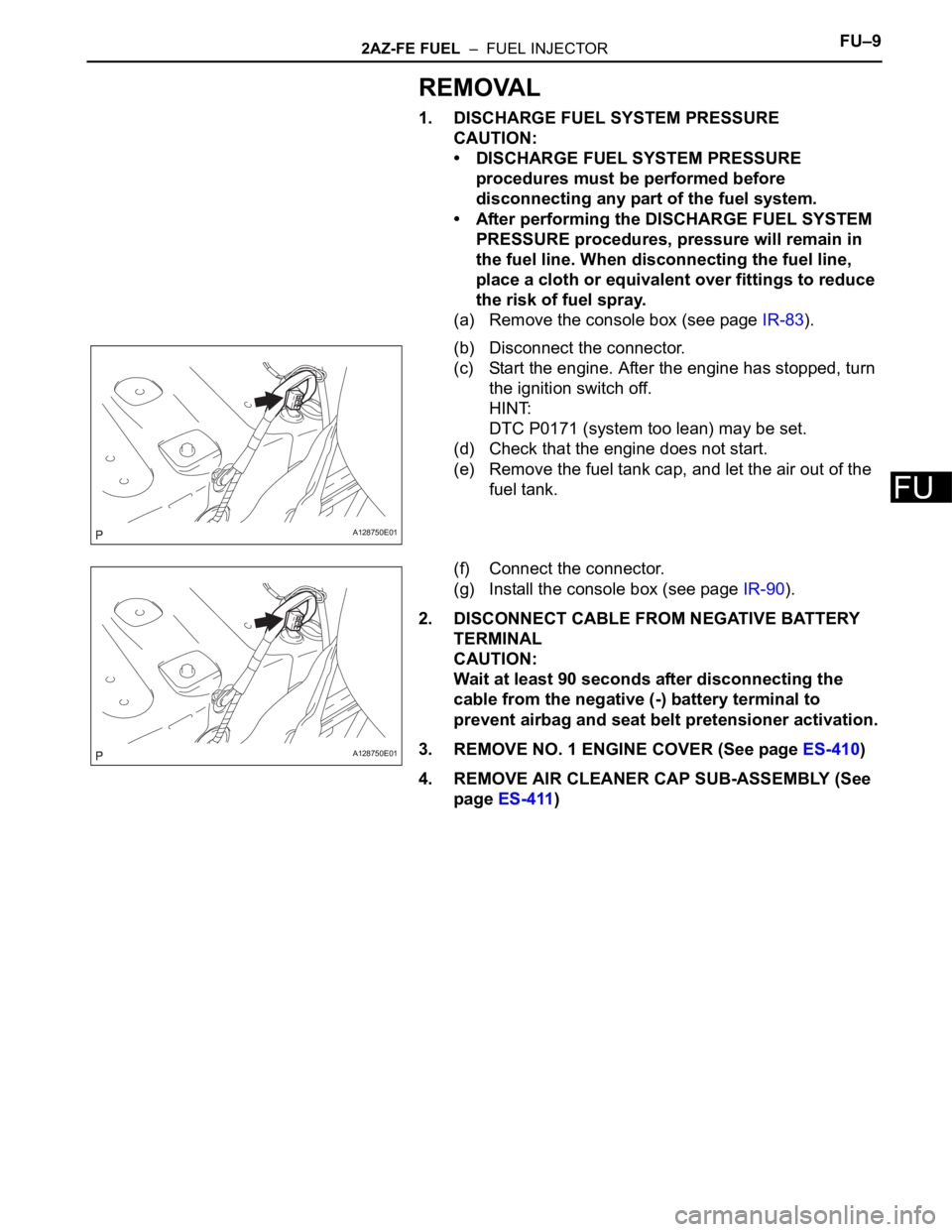
(b) Disconnect the connector.
(c) Start the engine. After the engine has stopped, turn
the ignition switch off.
HINT:
DTC P0171 (system too lean) may be set.
(d) Check that the engine does not start.
(e) Remove the fuel tank cap, and let the air out of the
fuel tank.
(f) Connect the connector.
(g) Install the console box (see page IR-90).
2. DISCONNECT CABLE FROM NEGATIVE BATTERY
TERMINAL
CAUTION:
Wait at least 90 seconds after disconnecting the
cable from the negative (-) battery terminal to
prevent airbag and seat belt pretensioner activation.
3. REMOVE NO. 1 ENGINE COVER (See page ES-410)
4. REMOVE AIR CLEANER CAP SUB-ASSEMBLY (See
page ES-411)
A128750E01
A128750E01