2006 TOYOTA RAV4 stop start
[x] Cancel search: stop startPage 1570 of 2000
BRAKE – BRAKE PEDALBR–15
BR
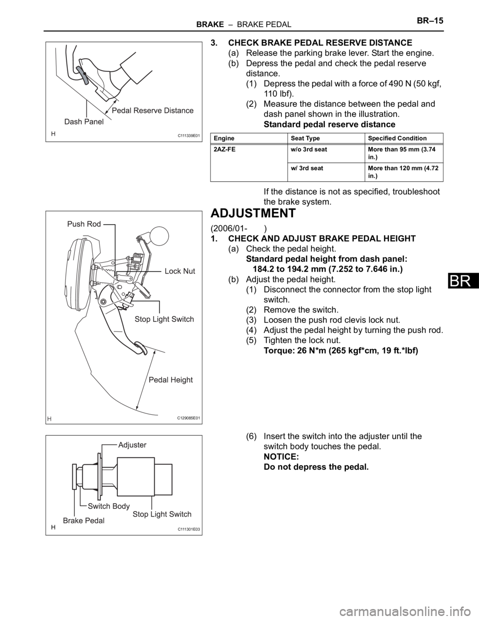
3. CHECK BRAKE PEDAL RESERVE DISTANCE
(a) Release the parking brake lever. Start the engine.
(b) Depress the pedal and check the pedal reserve
distance.
(1) Depress the pedal with a force of 490 N (50 kgf,
11 0 l b f ) .
(2) Measure the distance between the pedal and
dash panel shown in the illustration.
Standard pedal reserve distance
If the distance is not as specified, troubleshoot
the brake system.
ADJUSTMENT
(2006/01- )
1. CHECK AND ADJUST BRAKE PEDAL HEIGHT
(a) Check the pedal height.
Standard pedal height from dash panel:
184.2 to 194.2 mm (7.252 to 7.646 in.)
(b) Adjust the pedal height.
(1) Disconnect the connector from the stop light
switch.
(2) Remove the switch.
(3) Loosen the push rod clevis lock nut.
(4) Adjust the pedal height by turning the push rod.
(5) Tighten the lock nut.
Torque: 26 N*m (265 kgf*cm, 19 ft.*lbf)
(6) Insert the switch into the adjuster until the
switch body touches the pedal.
NOTICE:
Do not depress the pedal.
C 111 3 3 9 E 0 1Engine Seat Type Specified Condition
2AZ-FE w/o 3rd seat More than 95 mm (3.74
in.)
w/ 3rd seat More than 120 mm (4.72
in.)
C129085E01
C 111 3 0 1 E 0 3
Page 1571 of 2000
BR–16BRAKE – BRAKE PEDAL
BR
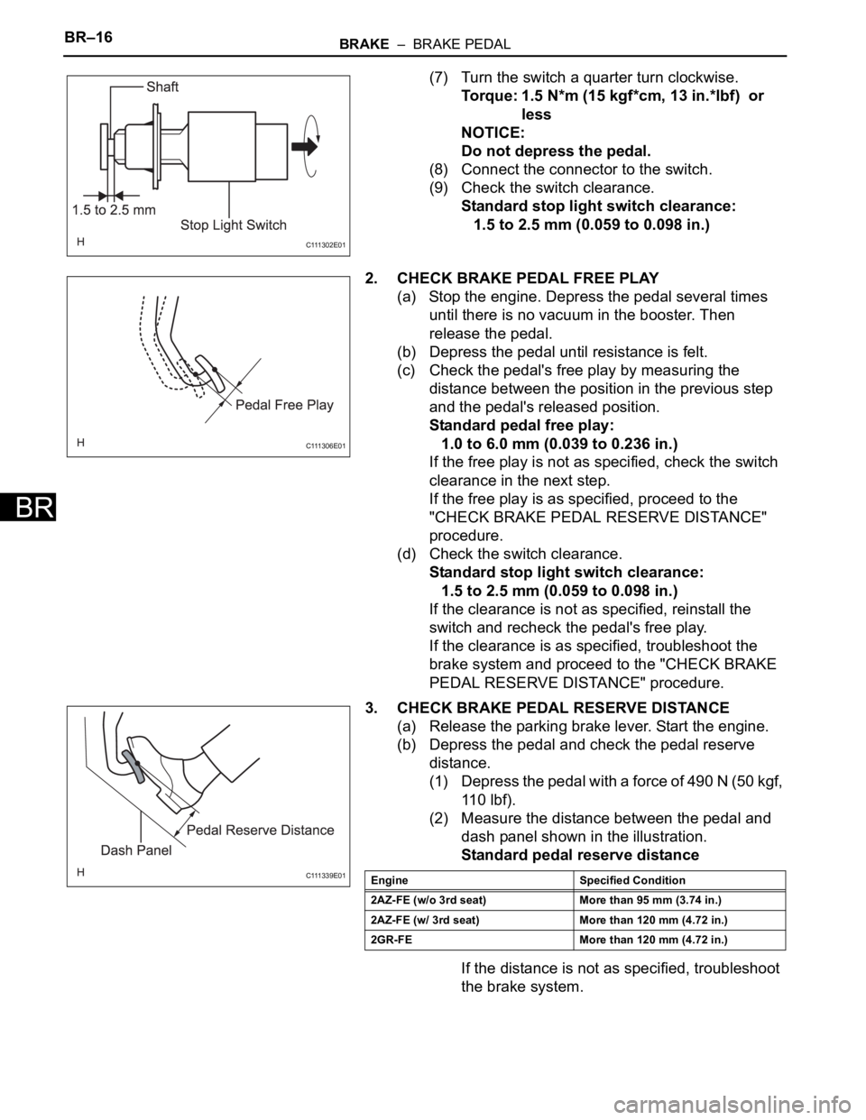
(7) Turn the switch a quarter turn clockwise.
Torque: 1.5 N*m (15 kgf*cm, 13 in.*lbf) or
less
NOTICE:
Do not depress the pedal.
(8) Connect the connector to the switch.
(9) Check the switch clearance.
Standard stop light switch clearance:
1.5 to 2.5 mm (0.059 to 0.098 in.)
2. CHECK BRAKE PEDAL FREE PLAY
(a) Stop the engine. Depress the pedal several times
until there is no vacuum in the booster. Then
release the pedal.
(b) Depress the pedal until resistance is felt.
(c) Check the pedal's free play by measuring the
distance between the position in the previous step
and the pedal's released position.
Standard pedal free play:
1.0 to 6.0 mm (0.039 to 0.236 in.)
If the free play is not as specified, check the switch
clearance in the next step.
If the free play is as specified, proceed to the
"CHECK BRAKE PEDAL RESERVE DISTANCE"
procedure.
(d) Check the switch clearance.
Standard stop light switch clearance:
1.5 to 2.5 mm (0.059 to 0.098 in.)
If the clearance is not as specified, reinstall the
switch and recheck the pedal's free play.
If the clearance is as specified, troubleshoot the
brake system and proceed to the "CHECK BRAKE
PEDAL RESERVE DISTANCE" procedure.
3. CHECK BRAKE PEDAL RESERVE DISTANCE
(a) Release the parking brake lever. Start the engine.
(b) Depress the pedal and check the pedal reserve
distance.
(1) Depress the pedal with a force of 490 N (50 kgf,
11 0 l b f ) .
(2) Measure the distance between the pedal and
dash panel shown in the illustration.
Standard pedal reserve distance
If the distance is not as specified, troubleshoot
the brake system.
C 111 3 0 2 E 0 1
C 111 3 0 6 E 0 1
C 111 3 3 9 E 0 1Engine Specified Condition
2AZ-FE (w/o 3rd seat) More than 95 mm (3.74 in.)
2AZ-FE (w/ 3rd seat) More than 120 mm (4.72 in.)
2GR-FE More than 120 mm (4.72 in.)
Page 1744 of 2000

SB–6SEAT BELT – SEAT BELT WARNING SYSTEM
SB
OPERATION CHECK
1. INSPECT DRIVER SIDE SEAT BELT WARNING LIGHT
(a) Turn the ignition switch ON.
(b) When the driver seat belt is not fastened, check that
the driver seat belt warning light on the combination
meter blinks.
(c) When the driver seat belt is fastened, check that the
driver seat belt warning light on the combination
meter is off.
2. INSPECT PASSENGER SIDE SEAT BELT WARNING
LIGHT (For Automatic Air Conditioning System)
(a) Turn the ignition switch ON.
(b) When the front passenger seat belt is not fastened
with the passenger seat occupied, check that the
front passenger seat belt warning light on the heater
control panel display blinks.
(c) When the front passenger seat belt is fastened with
the passenger seat occupied, check that the front
passenger seat belt warning light on the heater
control panel display is off.
3. REMOVE PASSENGER SIDE SEAT BELT WARNING
LIGHT (For Manual Air Conditioning System)
(a) Turn the ignition switch ON.
(b) When the front passenger seat belt is not fastened
with the passenger seat occupied, check that the
front passenger seat belt warning light on the clock
panel blinks.
(c) When the front passenger seat belt is fastened with
the passenger seat occupied, check that the front
passenger seat belt warning light on the clock panel
is off.
4. INSPECT SEAT BELT WARNING BUZZER
HINT:
If the buzzer does not sound, the buzzer cancel setting
may be set to ON.
(a) Turn the ignition switch ON.
(b) When the vehicle is driven at approximately 20 km/h
(12.4 mph) or more while the driver or front
passenger seat belt is not fastened, check that the
buzzer in the combination meter sounds at 1.2
second intervals for 30 seconds.
(c) 30 seconds after the buzzer has first sounded,
check that the buzzer sounds at 0.4 second
intervals for 90 seconds.
(d) 120 seconds after the buzzer has first sounded,
check that the buzzer stops.
(e) After the buzzer has stopped, turn the ignition
switch off and then start the engine again. Drive the
vehicle at approximately 25 km/h (16 mph) or more
while the driver or front passenger seat belt is not
fastened, and then check that the buzzer sounds
again.
Page 1751 of 2000

SEAT BELT – SEAT BELT WARNING SYSTEMSB–13
SB
ON-VEHICLE INSPECTION
1. CHECK DRIVER SIDE SEAT BELT WARNING LIGHT
(a) Turn the ignition switch ON.
(b) When the driver side seat belt is not fastened, check
that the combination meter's driver side seat belt
warning light starts blinking.
(c) When the seat belt is fastened, check that the
combination meter's driver side seat belt warning
light turns off.
2. CHECK PASSENGER SIDE SEAT BELT WARNING
LIGHT
(a) Turn the ignition switch ON.
(b) When the front passenger seat belt is not fastened,
check that the heater control panel's front
passenger side seat belt warning light starts
blinking.
(c) When the front passenger seat belt is fastened,
check that the heater control panel's front
passenger side seat belt warning light turns off.
3. CHECK SEAT BELT WARNING BUZZER
(a) Turn the ignition switch ON.
(b) After turning the ignition switch ON, if the vehicle is
driven at 20 km/h (12.4 mph) or more and the driver
side or front passenger side seat belt is not
fastened, check that the combination meter's buzzer
sounds at 1.2 second intervals for 30 seconds.
(c) 30 seconds after the buzzer first sounds, check that
the buzzer sounds at 0.4 second intervals for 90
seconds.
(d) 120 seconds after the buzzer has first sounded,
check that the buzzer stops.
(e) After the buzzer has stopped, turn the ignition
switch OFF and then start the engine again. With
the driver side or front passenger side seat belt
unfastened, drive the vehicle at 20 km/h (12.4 mph)
or more. Check that the buzzer sounds.
(f) After the buzzer has stopped, fasten the driver side
or front passenger side seat belt, drive the vehicle at
20 km/h (12.4 mph) or more, and then unfasten the
seat belt. Check that the buzzer sounds.
(g) After the buzzer has stopped, move the shift lever to
R. Then move the shift lever to D and with the driver
side or front passenger side seat belt unfastened,
drive the vehicle at 20 km/h (12.4 mph) or more.
Check that the buzzer sounds.
Page 1890 of 2000
WW–10WIPER AND WASHER – FRONT WIPER MOTOR AND LINK
WW
INSPECTION
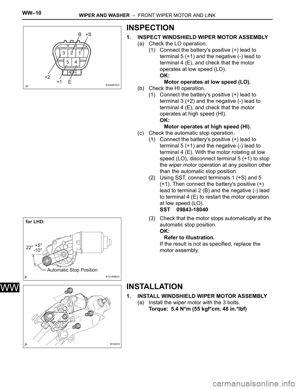
1. INSPECT WINDSHIELD WIPER MOTOR ASSEMBLY
(a) Check the LO operation.
(1) Connect the battery's positive (+) lead to
terminal 5 (+1) and the negative (-) lead to
terminal 4 (E), and check that the motor
operates at low speed (LO).
OK:
Motor operates at low speed (LO).
(b) Check the HI operation.
(1) Connect the battery's positive (+) lead to
terminal 3 (+2) and the negative (-) lead to
terminal 4 (E), and check that the motor
operates at high speed (HI).
OK:
Motor operates at high speed (HI).
(c) Check the automatic stop operation.
(1) Connect the battery's positive (+) lead to
terminal 5 (+1) and the negative (-) lead to
terminal 4 (E). With the motor rotating at low
speed (LO), disconnect terminal 5 (+1) to stop
the wiper motor operation at any position other
than the automatic stop position.
(2) Using SST, connect terminals 1 (+S) and 5
(+1). Then connect the battery's positive (+)
lead to terminal 2 (B) and the negative (-) lead
to terminal 4 (E) to restart the motor operation
at low speed (LO).
SST 09843-18040
(3) Check that the motor stops automatically at the
automatic stop position.
OK:
Refer to illustration.
If the result is not as specified, replace the
motor assembly.
INSTALLATION
1. INSTALL WINDSHIELD WIPER MOTOR ASSEMBLY
(a) Install the wiper motor with the 3 bolts.
Torque: 5.4 N*m (55 kgf*cm, 48 in.*lbf)
E034081E21
B131458E01
B136374
Page 1939 of 2000

2AZ-FE ENGINE CONTROL SYSTEM – SFI SYSTEMES–51
ES
CAT TEMP B1S2Estimated catalyst temperature
(sensor 2):
Min.: -40C, Max.: 6,513.5C--
S O2S B1S2Sub heated oxygen sensor
impedance (sensor2):
Min.: 0
, Max.: 21247.68
--
INI COOL TEMPEngine coolant temperature at
engine start:
Min.: -40
C, Max.: 120CClose to ambient air
temperature-
INI INTAKE TEMPIntake air temperature at engine
start:
Min.: -40
C, Max.: 120CClose to ambient air
temperature-
INJ VOLInjection volume (Cylinder 1):
Min.: 0 ml, Max.: 2.048 ml0 to 0.15 ml: IdlingQuantity of fuel injection volume
for 10 times
STARTER SIGStarter switch (STSW) signal:
ON or OFFON: Cranking -
PS SWPower steering signal:
ON or OFFON: Power steering operation -
PS SIGNALPower steering signal (history):
ON or OFFON: When steering wheel first
turned after battery terminals
connectedSignal status usually ON until
battery terminals disconnected
CTP SWClosed throttle position switch:
ON or OFF• ON: Throttle fully closed
• OFF: Throttle open-
A/C SIGNALA/C signal:
ON or OFFON: A/C ON -
PNP SW [NSW]PNP switch status:
ON or OFFON: P or N position -
ELECT LOAD SIGElectrical load signal:
ON or OFFON: Headlights or defogger
turned ON-
STOP LIGHT SWStop light switch:
ON or OFFON: Brake pedal depressed -
+BMWhether or not electric throttle
control system power inputted:
ON or OFFON: Ignition switch ON and
system normal-
+BM VOLTAGE+BM voltage:
Min.: 0, Max.: 19.9229 to 14 (V): Ignition switch ON
and system normalETCS service data
BATTERY VOLTAGEBattery voltage:
Min.: 0 V, Max.: 65.535 V9 to 14 V: Ignition switch ON -
ACTUATOR POWERActuator power supply:
ON or OFFON: Idling ETCS service data
ATM PRESSUREAtmospheric pressure:
Min.: 0 kPa, Max.: 255 kPaApproximately 100 kPa: Ignition
switch ON-
BATTERY CURRENTBattery current:
Min.: -100 A, Max.: 100 A--
BATTERY TEMPBattery temperature:
Min.: -45
C, Max.: 156.4 F--
ALT OUTPUT DUTYGenerator output duty ratio:
Min.: 0 %, Max.: 100 %- During charge control
ALT V NORMALRequest voltage when regulator
not under forced activation:
Min.: 0 V, Max.: 20 VBattery electrolyte temperature
varies (12.5 to 14.8 V) while
driving:
After engine startAlternator regulator output voltage
is out put
When performing Active Test,
value is 0V
ALT V TSTRequest voltage when regulator
under forced activation:
Min.: 0 V, Max.: 20 VRequest instruction voltage
value:
After engine startCharging control service data
When not performing Active Test,
value is 0V
EVAP (Purge) VSVPurge VSV status:
ON or OFF--
FUEL PUMP / SPDFuel pump status:
ON or OFFON: Engine running Active Test support data Intelligent Tester Display Measurement: Range (Display) Normal Condition*1 Diagnostic Note
Page 1944 of 2000
ES–562AZ-FE ENGINE CONTROL SYSTEM – SFI SYSTEM
ES
HINT:
*: When cranking the engine, each cylinder measures the
engine rpm.
In this ACTIVE TEST, the fuel and ignition of all cylinders is
cut, and cranking occurs for approximately 10 seconds. Then,
each cylinder measures the engine rpm. If a cylinder's engine
rpm is higher than the others, that cylinder's compression
pressure is compared to the others, and whether or not the
compression pressure is low can be determined.
1. Warm up the engine.
2. Turn the ignition switch OFF.
3. Connect the intelligent tester to the DLC3.
4. Turn the ignition switch ON and turn the intelligent tester
ON.
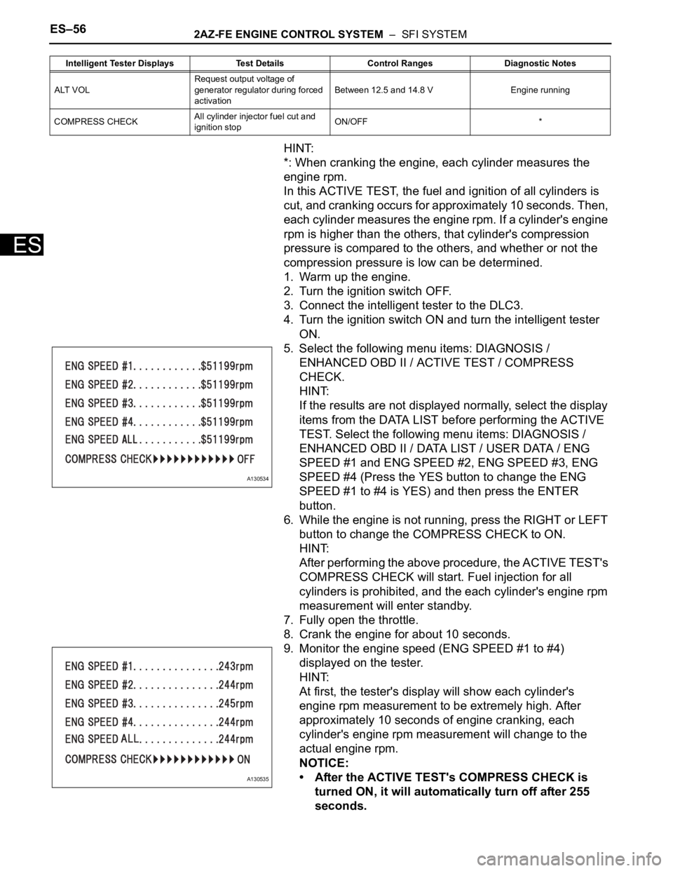
5. Select the following menu items: DIAGNOSIS /
ENHANCED OBD II / ACTIVE TEST / COMPRESS
CHECK.
HINT:
If the results are not displayed normally, select the display
items from the DATA LIST before performing the ACTIVE
TEST. Select the following menu items: DIAGNOSIS /
ENHANCED OBD II / DATA LIST / USER DATA / ENG
SPEED #1 and ENG SPEED #2, ENG SPEED #3, ENG
SPEED #4 (Press the YES button to change the ENG
SPEED #1 to #4 is YES) and then press the ENTER
button.
6. While the engine is not running, press the RIGHT or LEFT
button to change the COMPRESS CHECK to ON.
HINT:
After performing the above procedure, the ACTIVE TEST's
COMPRESS CHECK will start. Fuel injection for all
cylinders is prohibited, and the each cylinder's engine rpm
measurement will enter standby.
7. Fully open the throttle.
8. Crank the engine for about 10 seconds.
9. Monitor the engine speed (ENG SPEED #1 to #4)
displayed on the tester.
HINT:
At first, the tester's display will show each cylinder's
engine rpm measurement to be extremely high. After
approximately 10 seconds of engine cranking, each
cylinder's engine rpm measurement will change to the
actual engine rpm.
NOTICE:
• After the ACTIVE TEST's COMPRESS CHECK is
turned ON, it will automatically turn off after 255
seconds.
ALT VOLRequest output voltage of
generator regulator during forced
activationBetween 12.5 and 14.8 V Engine running
COMPRESS CHECKAll cylinder injector fuel cut and
ignition stopON/OFF * Intelligent Tester Displays Test Details Control Ranges Diagnostic Notes
A130534
A130535
Page 1953 of 2000
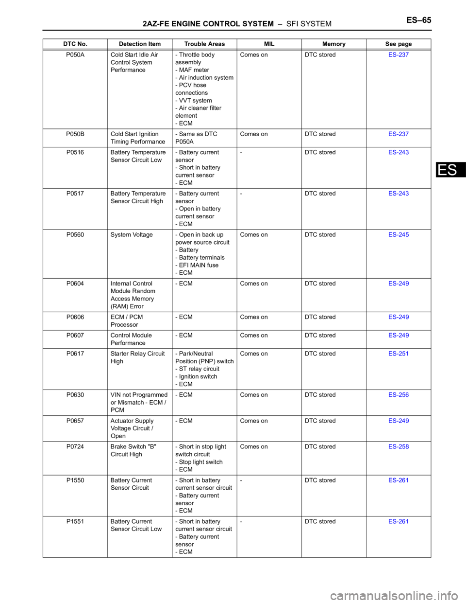
2AZ-FE ENGINE CONTROL SYSTEM – SFI SYSTEMES–65
ES
P050A Cold Start Idle Air
Control System
Performance- Throttle body
assembly
- MAF meter
- Air induction system
- PCV hose
connections
- VVT system
- Air cleaner filter
element
- ECMComes on DTC storedES-237
P050B Cold Start Ignition
Timing Performance- Same as DTC
P050AComes on DTC storedES-237
P0516 Battery Temperature
Sensor Circuit Low- Battery current
sensor
- Short in battery
current sensor
- ECM- DTC storedES-243
P0517 Battery Temperature
Sensor Circuit High- Battery current
sensor
- Open in battery
current sensor
- ECM- DTC storedES-243
P0560 System Voltage - Open in back up
power source circuit
- Battery
- Battery terminals
- EFI MAIN fuse
- ECMComes on DTC storedES-245
P0604 Internal Control
Module Random
Access Memory
(RAM) Error- ECM Comes on DTC storedES-249
P0606 ECM / PCM
Processor- ECM Comes on DTC storedES-249
P0607 Control Module
Performance- ECM Comes on DTC storedES-249
P0617 Starter Relay Circuit
High- Park/Neutral
Position (PNP) switch
- ST relay circuit
- Ignition switch
- ECMComes on DTC storedES-251
P0630 VIN not Programmed
or Mismatch - ECM /
PCM- ECM Comes on DTC storedES-256
P0657 Actuator Supply
Voltage Circuit /
Open- ECM Comes on DTC storedES-249
P0724 Brake Switch "B"
Circuit High- Short in stop light
switch circuit
- Stop light switch
- ECMComes on DTC storedES-258
P1550 Battery Current
Sensor Circuit- Short in battery
current sensor circuit
- Battery current
sensor
- ECM- DTC storedES-261
P1551 Battery Current
Sensor Circuit Low- Short in battery
current sensor circuit
- Battery current
sensor
- ECM- DTC storedES-261 DTC No. Detection Item Trouble Areas MIL Memory See page