2006 TOYOTA RAV4 stop start
[x] Cancel search: stop startPage 1148 of 2000

U151F AUTOMATIC TRANSAXLE – AUTOMATIC TRANSAXLE SYSTEMAX–29
AX
Harsh engagement (4th -> 5th)1. Valve body assemblyAX-142
2. C3 accumulatorAX-181
3. B3 U/D clutchAX-181
Harsh engagement (5th -> 4th)1. Valve body assemblyAX-142
2. B3 accumulatorAX-181
Slip or shudder (forward and reverse: after warm-up)1. Valve body assemblyAX-142
2. Oil strainerAX-142
3. C0 direct and O/D clutchAX-181
4. C1 forward clutchAX-181
5. C3 U/D clutchAX-181
6. B1 2nd and brakeAX-181
7. B3 U/D brakeAX-181
8. F1 No. 1 one-way clutchAX-181
9. F2 U/D one-way clutchAX-181
10. Torque converter clutchAX-179
Slip or shudder (particular position: just after engine
starts)Torque converter clutchAX-179
Slip or shudder (shift lever on R)1. C2 reverse clutchAX-181
2. B2 1st and reverse brakeAX-181
Slip or shudder (1st)1. C1 forward clutchAX-181
2. F1 No. 1 one-way clutchAX-181
3. F2 U/D one-way clutchAX-181
Slip or shudder (2nd) B1 2nd and O/D brakeAX-181
Slip or shudder (3rd) C0 direct and O/D clutchAX-181
Slip or shudder (4th) B1 2nd and O/D brakeAX-181
Slip or shudder (5th) C3 U/D clutchAX-181
Shift position too high or too low Shift solenoid valve SLTAX-120
No engine braking (1st to 4th/shift lever on D) B3 U/D brakeAX-181
No engine braking (1st/shift lever on L)1. Valve body assemblyAX-142
2. B2 1st and reverse brakeAX-181
No engine braking (2nd/shift lever on 2)1. Valve body assemblyAX-142
2. B1 2nd and O/D brakeAX-181
No engine braking (3rd/shift lever on 3) B3 U/D brakeAX-181
No kick-down Valve body assemblyAX-142
Poor acceleration (all positions)1. Shift solenoid valve SLTAX-120
2. Torque converter clutchAX-179
Poor acceleration (5th)1. C3 U/D clutchAX-181
2. U/D planetary gear unitAX-181
Engine stalls when starting off or stopping1. Shift solenoid valve DSLAX-65
2. Torque converter clutchAX-179 Symptom Suspected area See page
Page 1250 of 2000
AX–26U241E AUTOMATIC TRANSAXLE – AUTOMATIC TRANSAXLE SYSTEM
AX
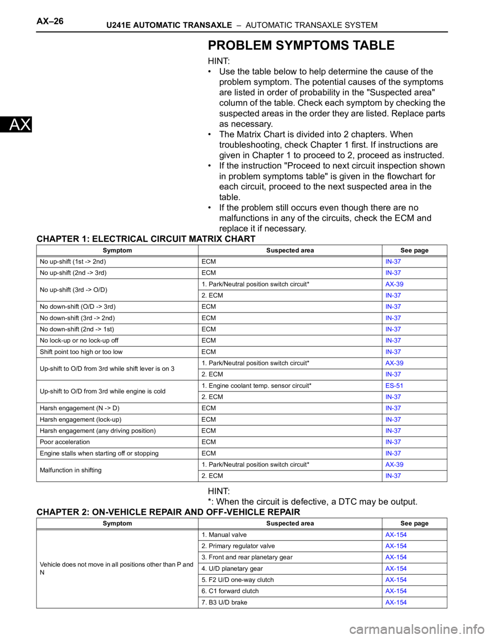
PROBLEM SYMPTOMS TABLE
HINT:
• Use the table below to help determine the cause of the
problem symptom. The potential causes of the symptoms
are listed in order of probability in the "Suspected area"
column of the table. Check each symptom by checking the
suspected areas in the order they are listed. Replace parts
as necessary.
• The Matrix Chart is divided into 2 chapters. When
troubleshooting, check Chapter 1 first. If instructions are
given in Chapter 1 to proceed to 2, proceed as instructed.
• If the instruction "Proceed to next circuit inspection shown
in problem symptoms table" is given in the flowchart for
each circuit, proceed to the next suspected area in the
table.
• If the problem still occurs even though there are no
malfunctions in any of the circuits, check the ECM and
replace it if necessary.
CHAPTER 1: ELECTRICAL CIRCUIT MATRIX CHART
HINT:
*: When the circuit is defective, a DTC may be output.
CHAPTER 2: ON-VEHICLE REPAIR AND OFF-VEHICLE REPAIR
Symptom Suspected area See page
No up-shift (1st -> 2nd) ECMIN-37
No up-shift (2nd -> 3rd) ECMIN-37
No up-shift (3rd -> O/D)1. Park/Neutral position switch circuit*AX-39
2. ECMIN-37
No down-shift (O/D -> 3rd) ECMIN-37
No down-shift (3rd -> 2nd) ECMIN-37
No down-shift (2nd -> 1st) ECMIN-37
No lock-up or no lock-up off ECMIN-37
Shift point too high or too low ECMIN-37
Up-shift to O/D from 3rd while shift lever is on 31. Park/Neutral position switch circuit*AX-39
2. ECMIN-37
Up-shift to O/D from 3rd while engine is cold1. Engine coolant temp. sensor circuit*ES-51
2. ECMIN-37
Harsh engagement (N -> D) ECMIN-37
Harsh engagement (lock-up) ECMIN-37
Harsh engagement (any driving position) ECMIN-37
Poor acceleration ECMIN-37
Engine stalls when starting off or stopping ECMIN-37
Malfunction in shifting1. Park/Neutral position switch circuit*AX-39
2. ECMIN-37
Symptom Suspected area See page
Vehicle does not move in all positions other than P and
N1. Manual valveAX-154
2. Primary regulator valveAX-154
3. Front and rear planetary gearAX-154
4. U/D planetary gearAX-154
5. F2 U/D one-way clutchAX-154
6. C1 forward clutchAX-154
7. B3 U/D brakeAX-154
Page 1252 of 2000

AX–28U241E AUTOMATIC TRANSAXLE – AUTOMATIC TRANSAXLE SYSTEM
AX
Poor acceleration (all positions)1. Torque converter clutchAX-152
2. U/D planetary gearAX-154
Poor acceleration (O/D)1. C3 U/D clutchAX-154
2. U/D planetary gearAX-154
Large shift shock or engine stalls when starting off or
stoppingTorque converter clutchAX-152
No kick-down Valve body assemblyAX-118 Symptom Suspected area See page
Page 1335 of 2000

GF1A TRANSFER – ACTIVE TORQUE CONTROL 4WD SYSTEMTF–7
TF2. DRIVING FUNCTION
Ambient Temperature Detects external ambient temperature and inputs it into body ECU
Electromagnetic Coupling Based on amount of current sent from 4WD control ECU, torque is
distributed to rear wheels
4WD Lock Switch Change of side auto mode for lock mode
4WD Lock Mode Indicator Light Lock mode control status is communicated to driver through indicator
light illumination
When lock mode is turned ON, indicator light blinks twice and then
remains illuminated.
When lock mode is turned OFF, indicator light turns OFF. Component Function
Vehicle Condition Status
Control at Vehicle Startup This controls the amount of sideway sliding that occurs at rear of
vehicles when accelerating from stop to improve acceleration and hill
climbing capacity
Slip Control at Vehicle Startup This helps prevent vehicle from sliding sideways. When accelerating a
stopped vehicle with the steering wheel turned, it ensures steering
stability
Slip Control This ensures high turning performance and that stability is not affected
by road surface conditions during mid and high speed running
Control During Acceleration This controls straight-line running when accelerating during mid and
high speeds to ensure straight-line stability of the vehicle
Page 1537 of 2000
BC–34BRAKE CONTROL – VEHICLE STABILITY CONTROL SYSTEM
BC
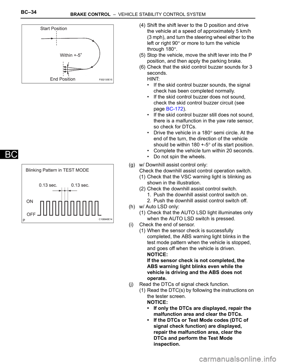
(4) Shift the shift lever to the D position and drive
the vehicle at a speed of approximately 5 km/h
(3 mph), and turn the steering wheel either to the
left or right 90
or more to turn the vehicle
through 180
.
(5) Stop the vehicle, move the shift lever into the P
position, and then apply the parking brake.
(6) Check that the skid control buzzer sounds for 3
seconds.
HINT:
• If the skid control buzzer sounds, the signal
check has been completed normally.
• If the skid control buzzer does not sound,
check the skid control buzzer circuit (see
page BC-172).
• If the skid control buzzer still does not sound,
there is a malfunction in the yaw rate sensor,
so check for DTCs.
• Drive the vehicle in a 180
semi circle. At the
end of the turn, the direction of the vehicle
should be within 180 +-5
of its start position.
• Complete the vehicle turn within 20 seconds.
• Do not spin the wheels.
(g) w/ Downhill assist control only:
Check the downhill assist control operation switch.
(1) Check that the VSC warning light is blinking as
shown in the illustration.
(2) Check the downhill assist control switch.
1. Push the downhill assist control switch on.
2. Push the downhill assist control switch off.
(h) w/ Auto LSD only:
(1) Check that the AUTO LSD light illuminates only
when the AUTO LSD switch is pressed.
(i) Check the end of sensor.
(1) When the sensor check is successfully
completed, the ABS warning light blinks in the
test mode pattern when the vehicle is stopped,
and goes off when the vehicle is driven.
NOTICE:
If the sensor check is not completed, the
ABS warning light blinks even while the
vehicle is driving and the ABS does not
operate.
(j) Read the DTCs of signal check function.
(1) Read the DTC(s) by following the instructions on
the tester screen.
NOTICE:
• If only the DTCs are displayed, repair the
malfunction area and clear the DTCs.
• If the DTCs or Test Mode codes (DTC of
signal check function) are displayed,
repair the malfunction area, clear the
DTCs and perform the Test Mode
inspection.
F002135E15
C108848E14
Page 1540 of 2000
BRAKE CONTROL – VEHICLE STABILITY CONTROL SYSTEMBC–37
BC
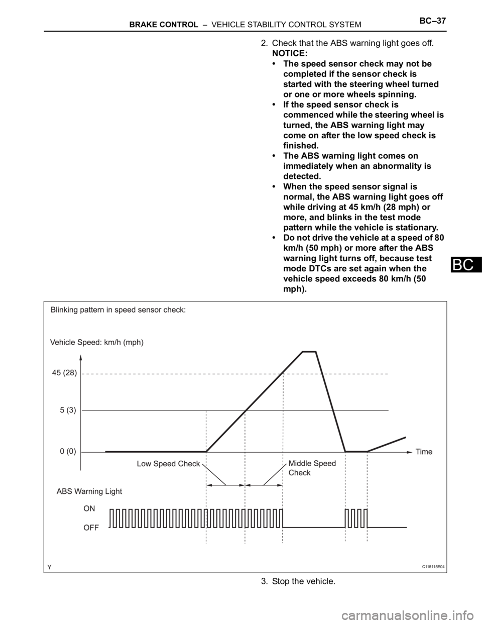
2. Check that the ABS warning light goes off.
NOTICE:
• The speed sensor check may not be
completed if the sensor check is
started with the steering wheel turned
or one or more wheels spinning.
• If the speed sensor check is
commenced while the steering wheel is
turned, the ABS warning light may
come on after the low speed check is
finished.
• The ABS warning light comes on
immediately when an abnormality is
detected.
• When the speed sensor signal is
normal, the ABS warning light goes off
while driving at 45 km/h (28 mph) or
more, and blinks in the test mode
pattern while the vehicle is stationary.
• Do not drive the vehicle at a speed of 80
km/h (50 mph) or more after the ABS
warning light turns off, because test
mode DTCs are set again when the
vehicle speed exceeds 80 km/h (50
mph).
3. Stop the vehicle.
C115115E04
Page 1541 of 2000
BC–38BRAKE CONTROL – VEHICLE STABILITY CONTROL SYSTEM
BC
(f) Check the yaw rate sensor.
(1) Move the shift lever to P and set the parking
brake lever.
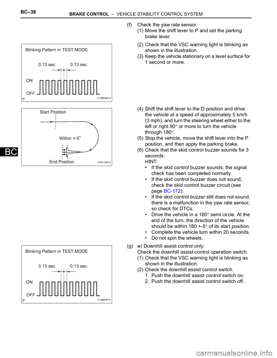
(2) Check that the VSC warning light is blinking as
shown in the illustration.
(3) Keep the vehicle stationary on a level surface for
1 second or more.
(4) Shift the shift lever to the D position and drive
the vehicle at a speed of approximately 5 km/h
(3 mph), and turn the steering wheel either to the
left or right 90
or more to turn the vehicle
through 180
.
(5) Stop the vehicle, move the shift lever into the P
position, and then apply the parking brake.
(6) Check that the skid control buzzer sounds for 3
seconds.
HINT:
• If the skid control buzzer sounds, the signal
check has been completed normally.
• If the skid control buzzer does not sound,
check the skid control buzzer circuit (see
page BC-172).
• If the skid control buzzer still does not sound,
there is a malfunction in the yaw rate sensor,
so check for DTCs.
• Drive the vehicle in a 180
semi circle. At the
end of the turn, the direction of the vehicle
should be within 180 +-5
of its start position.
• Complete the vehicle turn within 20 seconds.
• Do not spin the wheels.
(g) w/ Downhill assist control only:
Check the downhill assist control operation switch.
(1) Check that the VSC warning light is blinking as
shown in the illustration.
(2) Check the downhill assist control switch.
1. Push the downhill assist control switch on.
2. Push the downhill assist control switch off.
C108848E14
F002135E15
C108848E14
Page 1558 of 2000
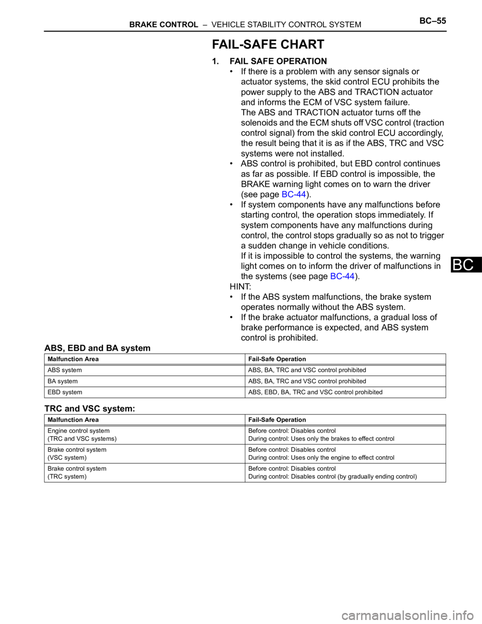
BRAKE CONTROL – VEHICLE STABILITY CONTROL SYSTEMBC–55
BC
FAIL-SAFE CHART
1. FAIL SAFE OPERATION
• If there is a problem with any sensor signals or
actuator systems, the skid control ECU prohibits the
power supply to the ABS and TRACTION actuator
and informs the ECM of VSC system failure.
The ABS and TRACTION actuator turns off the
solenoids and the ECM s huts off VSC control (traction
control signal) from the skid control ECU accordingly,
the result being that it is as if the ABS, TRC and VSC
systems were not installed.
• ABS control is prohibited, but EBD control continues
as far as possible. If EBD control is impossible, the
BRAKE warning light comes on to warn the driver
(see page BC-44).
• If system components have any malfunctions before
starting control, the operation stops immediately. If
system components have any malfunctions during
control, the control stops gradually so as not to trigger
a sudden change in vehicle conditions.
If it is impossible to control the systems, the warning
light comes on to inform the driver of malfunctions in
the systems (see page BC-44).
HINT:
• If the ABS system malfunctions, the brake system
operates normally without the ABS system.
• If the brake actuator malfunctions, a gradual loss of
brake performance is expected, and ABS system
control is prohibited.
ABS, EBD and BA system
TRC and VSC system:
Malfunction Area Fail-Safe Operation
ABS system ABS, BA, TRC and VSC control prohibited
BA system ABS, BA, TRC and VSC control prohibited
EBD system ABS, EBD, BA, TRC and VSC control prohibited
Malfunction Area Fail-Safe Operation
Engine control system
(TRC and VSC systems)Before control: Disables control
During control: Uses only the brakes to effect control
Brake control system
(VSC system)Before control: Disables control
During control: Uses only the engine to effect control
Brake control system
(TRC system)Before control: Disables control
During control: Disables control (by gradually ending control)