Page 1208 of 1556
Downloaded from www.Manualslib.com manuals search engine 9A-41 Wiring Systems:
10 A ABSABS control module
G sensor
BLANK BLANK BLANK
15 A STOP Brake light switch
20 A D/L BCM
BLANK BLANK BLANK
10 A ST SIG Starting motor relay
BLANK BLANK BLANK
10 A IG2 SIG Blower fan relay
10 A TAIL Tail light relay
15 A DOMEAudio
BCM
COMB meter
DLC
ECM
Interior light
ICM
TCM
Rear interior light
Luggage compartment light
Main switch (Key switch)
Multi information display
KLS ECM
30 A RR DEFRear defogger relay
Mirror motor (R)
Mirror motor (L)
15 A HORN-HAZHorn relay
Flasher relay
BLANK BLANK BLANK
BLANK BLANK BLANK
30 A P/WPower window main switch
Front power window sub switch
Rear power window sub switch (R)
Rear power window sub switch (L) No. Fuse Description on the cover Protected circuit
Page 1225 of 1556
Downloaded from www.Manualslib.com manuals search engine Wiring Systems: 9A-58
A-1 Cranking System Circuit DiagramS6RW0D910E002
Starting motor
relay
W
"A-5"
ECM
E225
C1951C1961
Starting motor
M
BLK
1
BLK/GRY
C2821
Battery
E371
C3433
RED
Individual circuit
fuse box (No.1)
8
30A
33
10A
WHTWHT
J/B
E32510
42
3 1
RED/WHT
ST
ST SIG
YEL/GRNYEL/GRN
YG
"A-5"
ECM
GRN/WHT
G1472
YEL/GRN
YEL/GRN
G2734
+B1
LOCK
ACC
ON
STACC IG1 IG2STOUT
IN
+B2
2P
R
ND2L
Transaxle
range
sensor
C166
E371
C3433
A/T M/T
3
YEL/GRN
YEL
YEL
M15A engine, M16A engine
J20A engine A
9
2AB
6
8AB
B
I6RW0C910933-01
Page 1229 of 1556
Downloaded from www.Manualslib.com manuals search engine Wiring Systems: 9A-62
A-4 Cooling System Circuit Diagram (M15A engine, M16A engine)S6RW0D910E005
E65
4
5
9
"A-5"
Lg
BR
BW
Relay
Motor
E2223
1
2
1
BLU/REDLT GRNBRN/WHT
GRYBLK/RED
BLK/YELBLK/YEL
30ARDTR
10
E2211
2
15AFI
1
3
4
Main relay
BLK
ECM
Individual circuit
fuse box (No.1)
M
I6RW0C910919-01
Page 1230 of 1556
Downloaded from www.Manualslib.com manuals search engine 9A-63 Wiring Systems:
A-4 Cooling System Circuit Diagram (J20A engine)S6RW0D910E040
E65
4
5
9
LT GRN
"A-5"
Lg
BRBBBW
G
BRN/WHT
BW
BLK/YELBLK/YEL
Relay #1
Motor
E2223
1
243
1
BLU/REDBLU/REDBLU/BLKBLKBLU/RED
BLU/RED
GRY
GRYBLU/WHT
GRNGRN
30ARDTR
10
E2211
2
15AFI
1
3
4
Main relay
BLK
BLK
BLK/RED
ECM
"A-5"
ECM
Individual circuit
fuse box (No.1)
4
5
Relay #2
E2231
35
4
Relay #3
E2241
3
M
I7RW01910924-02
Page 1231 of 1556

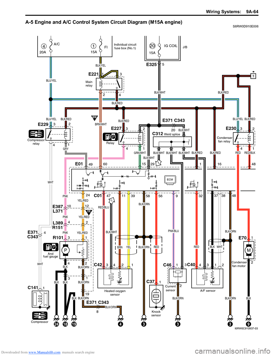
Downloaded from www.Manualslib.com manuals search engine Wiring Systems: 9A-64
A-5 Engine and A/C Control System Circuit Diagram (M15A engine)S6RW0D910E006
YEL/RED
E387
L3711012
L389
R15142
PNKYEL/RED
P
PNKYEL/RED
31
433
31
E371 C343
BLK/ORN
BLK/ORN
BLK/ORN
BLK/ORN
19
8
BLK42
R101
1
And
fuel gauge
Main
relay
1
BLK/WHT
BLK/REDBLU/YEL
C312Weld splice
GRN/WHTBLK/WHT
BLK/WHT
BLK/WHT
IG COILJ/B1
15A
FI
BLK/YEL
E2211
23
415A
20
BRN/WHT
BW
YR
4
20A
A/C
Compressor
relay
E229
Relay
BLU/YEL
BLU/YEL
Compressor
C1411
E3255
E371 C343
20
E371
C3434BLK/WHT
C42C40
Heated oxygen
sensor
RED/BLU
BRN
A/F sensorCondenser
fan motor Condenser
fan relay
BLK
BLK/ORN
BLK/ORN
RED
C01
1
34 2 143 12
4711393237
WHT
3848PNK
ECM
142
3
WHT
WHT
BLK/RED
BLK/REDBLK/WHT
BLK/RED
BLK/RED
BLK/RED
E01496015291
GRY
E22732
4
1
E23032
4
1
YELBLK/ORN
24
BLKBLK
58 56
BLK/REDRED
16 48
182419
Individual circuit
fuse box (No.1)
BLKBLKBLK/ORNBLK/ORN
93
RED/BLK
M
1
2E70
9
PNK/BLU
RED
Knock
sensor
C371
BLK/WHT
Current
sensor
C461
23
I6RW0C910937-03
Page 1232 of 1556
Downloaded from www.Manualslib.com manuals search engine 9A-65 Wiring Systems:
2C39
LT GRN
1
C47C01
C01
GRN/ORNGRN/REDBRN/YEL
WHT/RED
C122
3
BLK/REDBLK/REDBLK/REDBLK/RED
55
RED/BLKGRY/RED
GRY/BLU
Weld spliceC311
EGR
valve
4
6312
5
3
4 5 6
MAP
sensor
C363
1
2
C124
ECM
C912
1C922
1C932
1C942
1
#2 #1#3
#4
BLU/REDBLU/WHTBLU/YELBLU/ORN
BLK/RED
BLK/RED
BLU/BLK
EVAP
canister
purge
valve
C123
ECT
sensor
GRY/BLU
GRY/BLUBLK/REDGRYBLU/YELBRN/WHT
"A-4"
Lg
30ARDTR
10
Relay
motor
"A-1"
Generator
BLU/REDLT GRNBRNGRN
BR
BY
46E015017
1
1
2
13 17
16 2
1
242528
26
27
21 4
3
5
LT GRN/BLK
2
57
E371 C343
18
19
OCV
1
2
6059
BLK/REDBLK/REDGRYGRY
BLK/RED
BLK/RED
BLK/RED
4
32
1E226
PNK/BLK
BW
8
GRY/BLU
YEL
Individual circuit
fuse box (No.1)
15ATHR
MOR
3
YEL/BLK
MAF sensor
4
53
1E222
Throttle
motor
relay
M
I6RW0C910936-04
Page 1233 of 1556
Downloaded from www.Manualslib.com manuals search engine Wiring Systems: 9A-66
Weld spliceC311
CKP
sensor
3C31
51
PNKBLK/ORN
BLK/RED
12
GW
J/B
2
15ASTOP
30
15ADOME
37
E0120
GRN/WHT
GRN/WHT
GRN
E3234
E181
Brake
light
switch
1 2
ECM
2
CMP
sensor
C01 C01
BLK
BLK
BLK
3463
1529 3031
1C32
52C01 E0122302813
RED/YEL
BLK/ORNBLKBLKBLKBLK
BLK/REDBLK/RED
32
J/B
E3251
2
YG
YEL/GRNYEL/BLKWHT/REDWHTYEL/RED
Starting
motor
relayICM
"A-7"YBYR
BR
2
W"A-1"
Starting
motor
relay
"A-1"
VSS
"A-6"
C343
E3711
I6RW0C910938-02
Page 1234 of 1556
Downloaded from www.Manualslib.com manuals search engine 9A-67 Wiring Systems:
TCM
WHTRED
717C06
4944C0114E013641351227C01212050
ECM
WHT
ABS
Cont.M
APP sensor Throttle position sensor
Throttle sensor
SUB
open close open close open close
open close
MAIN SUB MAIN
Throttle
motor
REDBLUGRNBRNWHTYELREDBLKWHTGRNREDYELBLU
E08
4
19
1
12E1911
6C482
156435234
RW
RW
33414054534544535251565554E01 C01
(CAN)
(CAN)
WHTGRY
GRN/WHTGRN/YELBRN
B
P/S
Cont.M
"F-3"
RED/BLU
GWGY
IG COIL
#2 IG COIL
#1
BW
Mode control
switch"A-3"
"E-1"
RB
"E-2"
ORNGRY/REDRED/BLU
GRY/REDRED/BLU
EVAP thermistor
1
3G32
8
ORN
WHT/BLKBLU/WHTORN
E382
G334
BW
Auto
Unit
A/C
pressure
sensorE36
C343
E3711011
2
3
BLU/WHTORN
915
8
915
WHT/BLKBLU/WHT
Auto A/C
Manual A/C
1
3
I6RW0C910939-03