2006 SUZUKI SX4 Motor
[x] Cancel search: MotorPage 1164 of 1556
Downloaded from www.Manualslib.com manuals search engine 9-iv Table of Contents
Front Speaker Removal and Installation (If
Equipped) ........................................................9C-19
Rear Speaker Removal and Installation (If
Equipped) ........................................................9C-19
GPS Antenna Removal and Installation (If
Equipped) ........................................................9C-20
Horn Removal and Installation ..........................9C-20
Horn Inspection .................................................9C-20
Horn Relay Inspection .......................................9C-20
Antenna Base Removal and Installation ...........9C-21
Remote Audio Control Switch Removal and
Installation (If Equipped) .................................9C-21
Remote Audio Control Switch Inspection (If
Equipped) ........................................................9C-22
Vehicle Speed Signal Inspection (For Audio
Unit) (If Equipped) ...........................................9C-22
Specifications .....................................................9C-22
Tightening Torque Specifications ......................9C-22
Wipers / Washers .................................... 9D-1
Diagnostic Information and Procedures ............ 9D-1
Front Wiper and Washer Symptom Diagnosis ....9D-1
Rear Wiper and Washer Symptom Diagnosis..... 9D-1
Repair Instructions ..............................................9D-2
Wipers and Washers Components .....................9D-2
Washer Tank and Washer Pump Removal
and Installation ..................................................9D-3
Washer Pump Inspection ....................................9D-3
Windshield Wiper Removal and Installation ........9D-3
Windshield Wiper Motor Inspection.....................9D-4
Rear Wiper Removal and Installation.................. 9D-6
Rear Wiper Motor Inspection ..............................9D-7
Windshield Wiper and Washer Switch
Removal and Installation ................................... 9D-8
Windshield Wiper and Washer Switch
Inspection .......................................................... 9D-8
Rear Wiper and Washer Switch Removal and
Installation .......................................................9D-10
Rear Wiper and Washer Switch Inspection.......9D-10
Rear Wiper Relay Removal and Installation .....9D-10
Rear Wiper Relay Inspection ............................9D-10
Specifications .....................................................9D-11
Tightening Torque Specifications ......................9D-11
Glass / Windows / Mirrors .......................9E-1
Precautions........................................................... 9E-1
Precautions for Power Window Service
(Pinching Prevention Function Model) .............. 9E-1
General Description ............................................. 9E-1
Rear End Door Window Defogger System
Description ........................................................ 9E-1
Schematic and Routing Diagram ........................ 9E-2
Power Window Circuit Diagram (Pinching
Prevention Function Model) .............................. 9E-2
Diagnostic Information and Procedures ............ 9E-3
Rear End door Window Defogger Symptom
Diagnosis .......................................................... 9E-3
Power Window Control System Symptom
Diagnosis .......................................................... 9E-3Inspection of Pinching Prevention Function
(Pinching Prevention Function Model) .............. 9E-4
Power Door Mirror Control System Symptom
Diagnosis .......................................................... 9E-4
Door Mirror Heater Symptom Diagnosis (If
Equipped) .......................................................... 9E-5
Repair Instructions .............................................. 9E-5
Windshield Components ..................................... 9E-5
Windshield Removal and Installation .................. 9E-6
Front Pillar Window Components...................... 9E-10
Front Pillar Window Removal and Installation... 9E-10
Rear Quarter Window Components .................. 9E-11
Rear Quarter Window Removal and
Installation ....................................................... 9E-11
Rear End Door Window Components ............... 9E-12
Rear End Door Glass Removal and
Installation ....................................................... 9E-12
Front Door Window Components ...................... 9E-13
Front Door Glass Removal and Installation ...... 9E-14
Front Door Window Regulator Removal and
Installation ....................................................... 9E-15
Front Door Window Regulator Inspection ......... 9E-15
Rear Door Window Components ...................... 9E-16
Rear Door Glass Removal and Installation ....... 9E-16
Rear Door Window Regulator Removal and
Installation ....................................................... 9E-18
Rear Door Window Regulator Inspection .......... 9E-18
Rear End Door Window Defogger Switch
Inspection ........................................................ 9E-18
Rear End Door Window Defogger Relay
Inspection ........................................................ 9E-19
Rear End Door Window Defogger Wire
Inspection ........................................................ 9E-19
Rear End Door Window Defogger Wire
Repair.............................................................. 9E-20
Power Window Main Switch Inspection ............ 9E-20
Power Window Sub Switch Inspection .............. 9E-22
Pulse Sensor and Its Circuit Inspection
(Pinching Prevention Function Model) ............ 9E-23
Power Window Main Switch Initialization
(Pinching Prevention Function Model) ............ 9E-24
Door Mirror Components................................... 9E-24
Door Mirror Removal and Installation................ 9E-25
Power Door Mirror Switch Inspection ................ 9E-25
Power Door Mirror Actuator Inspection ............. 9E-25
Door Mirror Heater Inspection (If Equipped) ..... 9E-26
Door Mirror Heater Switch Inspection (If
Equipped) ........................................................ 9E-26
Special Tools and Equipment ........................... 9E-26
Recommended Service Material ....................... 9E-26
Security and Locks...................................9F-1
General Description ............................................. 9F-1
Key Coding Construction .................................... 9F-1
Rear End Door Opener System Description ....... 9F-1
Component Location ........................................... 9F-2
Power Door Lock and Keyless Entry System
Component Location (If Equipped) ................... 9F-2
Diagnostic Information and Procedures ............ 9F-3
Page 1169 of 1556
Downloaded from www.Manualslib.com manuals search engine Wiring Systems: 9A-2
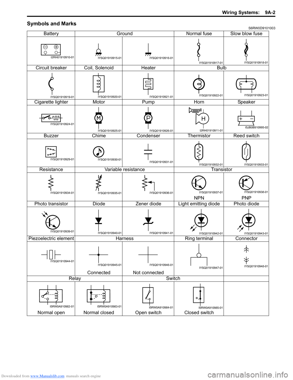
Symbols and MarksS6RW0D9101003
Battery Ground Normal fuse Slow blow fuse
Circuit breaker Coil, Solenoid Heater Bulb
Cigarette lighter Motor Pump Horn Speaker
Buzzer Chime Condenser Thermistor Reed switch
Resistance Variable resistance Transistor
NPN PNP
Photo transistor Diode Zener diode Light emitting diode Photo diode
Piezoelectric element Harness Ring terminal Connector
Connected Not connected
Relay Switch
Normal open Normal closed Open switch Closed switch
I2RH01910910-01IYSQ01910915-01IYSQ01910916-01
IYSQ01910917-01IYSQ01910918-01
IYSQ01910919-01IYSQ01910920-01IYSQ01910921-01IYSQ01910922-01IYSQ01910923-01
IYSQ01910924-01
IYSQ01910925-01IYSQ01910926-01
H
I2RH01910911-01I5JB0B910995-02
IYSQ01910929-01IYSQ01910930-01IYSQ01910931-01IYSQ01910932-01IYSQ01910933-01
IYSQ01910934-01IYSQ01910935-01IYSQ01910936-01IYSQ01910937-01IYSQ01910938-01
IYSQ01910939-01IYSQ01910940-01IYSQ01910941-01IYSQ01910942-01IYSQ01910943-01
IYSQ01910944-01IYSQ01910945-01IYSQ01910946-01IYSQ01910947-01IYSQ01910948-01
I5RW0A910982-01I5RW0A910983-01I5RW0A910984-01I5RW0A910985-01
Page 1175 of 1556
Downloaded from www.Manualslib.com manuals search engine Wiring Systems: 9A-8
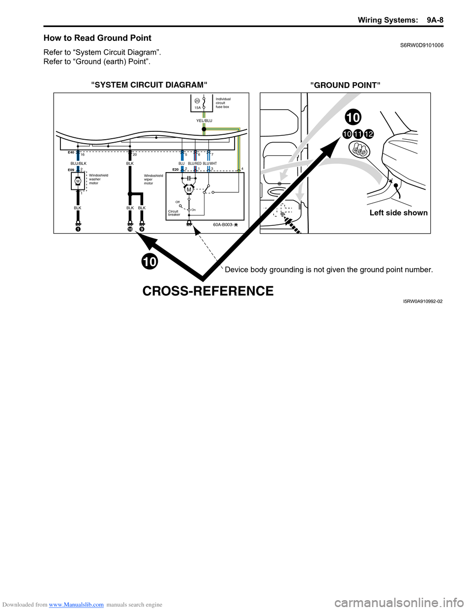
How to Read Ground PointS6RW0D9101006
Refer to “System Circuit Diagram”.
Refer to “Ground (earth) Point”.
Left side shown
101112
"SYSTEM CIRCUIT DIAGRAM"
"GROUND POINT"
CROSS-REFERENCE
Windoshield
washer
motorIndividual
circuit
fuse box
2015A
Windoshield
wiper
motor E40
E09E20 16
2
1
Off
On
Circuit
breaker
60A-B003-
YEL/BLU
1
205
2
134
67
BLU/BLK
BLK
10
BLK
BLK
9
10
10
BLK
M
BLUBLU/WHTBLU/RED
M
Device body grounding is not given the ground point number.
I5RW0A910992-02
Page 1177 of 1556
![SUZUKI SX4 2006 1.G Service Workshop Manual Downloaded from www.Manualslib.com manuals search engine Wiring Systems: 9A-10
[D]: Terminals-in-one-connector mark
[E]: Wire color
[F]: Shield wire
[G]: Ground point
[H]: “From” or “To” (Wit SUZUKI SX4 2006 1.G Service Workshop Manual Downloaded from www.Manualslib.com manuals search engine Wiring Systems: 9A-10
[D]: Terminals-in-one-connector mark
[E]: Wire color
[F]: Shield wire
[G]: Ground point
[H]: “From” or “To” (Wit](/manual-img/20/7612/w960_7612-1176.png)
Downloaded from www.Manualslib.com manuals search engine Wiring Systems: 9A-10
[D]: Terminals-in-one-connector mark
[E]: Wire color
[F]: Shield wire
[G]: Ground point
[H]: “From” or “To” (With ID letter (s))
[I]: Specification variation
The white arrow between A and B means “or”.
[J]: “From” (With ID letter (s))
[K] “To” (With ID letter (s))
[L]: Connector code
[M]: Terminal No.
[N]: Symbol mark
[O]: “SEE” mark
Switch
BLU
BLU
GRN/BLK
GRN/REDGRN/BLK
12
GRN
GRN
C262
1
BLK
5
BLK
2 1
C40
GRN/BLK
"XX"
Solenoid FuseFuse
3
15A
Main
relay
ON OFF
1
15A
6
20A
1
Sensor 1
2
8
BRN/RED
E521
2E521
BRN/RED
RED
2
BRN/REDBRN/RED
MotorM M
655
A
B
AB5
6
1
2
56464 4-DOOR
2-DOOR
2
C71
E03
E34
O06
C31
E19
[A]
[B]
[C]
[F]
[G]
[H] [D][I] [K] [L]
E3375E341
21
43E08
ORNWHTYEL
RED
YELYEL/REDGRN/RED
4
3
YEL
BLK/RED
ORN
GRN
GRN
BA
GRN
GRN
2
XX
Cont.M
[J]
[E]
[N] [O] [M]
GBGR
Y
Y
GB
P
3
4
2
3
L50 G20
1
GR
Y
BLK
BLK
GR
I5RW0A910994-02
Page 1179 of 1556
Downloaded from www.Manualslib.com manuals search engine Wiring Systems: 9A-12
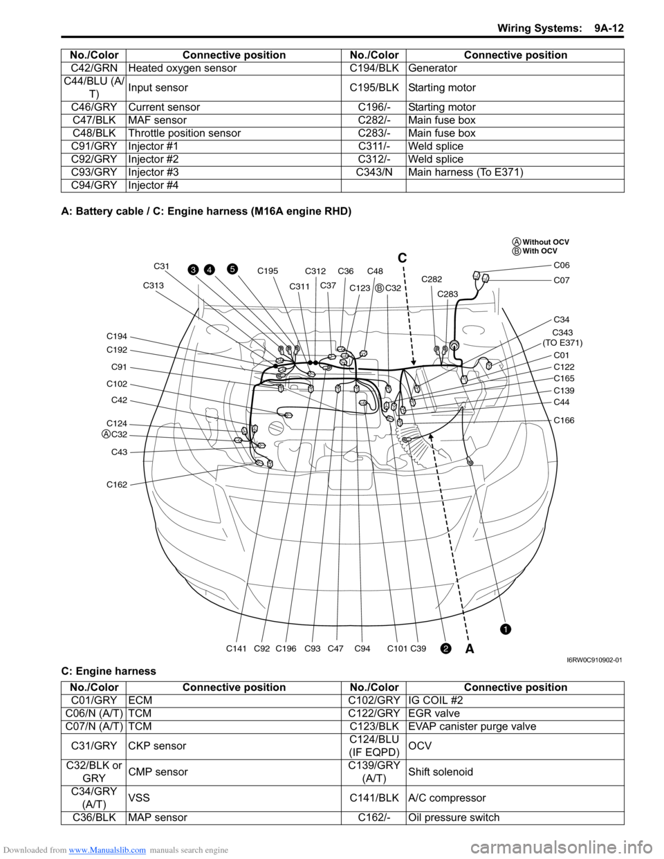
A: Battery cable / C: Engine harness (M16A engine RHD)
C: Engine harnessC42/GRN Heated oxygen sensor C194/BLK Generator
C44/BLU (A/
T)Input sensor C195/BLK Starting motor
C46/GRY Current sensor C196/- Starting motor
C47/BLK MAF sensor C282/- Main fuse box
C48/BLK Throttle position sensor C283/- Main fuse box
C91/GRY Injector #1 C311/- Weld splice
C92/GRY Injector #2 C312/- Weld splice
C93/GRY Injector #3 C343/N Main harness (To E371)
C94/GRY Injector #4 No./Color Connective position No./Color Connective position
C124
C32
C42
C102
C91
C192
C194
C43
C162
C141C196
C195
C93C94C101C39C92
C31
C311C313C312
C36C48
C37C123
C47C32C282
C283
C343
(TO E371)
C01
C34
C07
C06
C122
C165
C139
C44
C166
43
2
1
5C
A
Without OCV
With OCV A
A
B
B
I6RW0C910902-01
No./Color Connective position No./Color Connective position
C01/GRY ECM C102/GRY IG COIL #2
C06/N (A/T) TCM C122/GRY EGR valve
C07/N (A/T) TCM C123/BLK EVAP canister purge valve
C31/GRY CKP sensorC124/BLU
(IF EQPD)OCV
C32/BLK or
GRYCMP sensorC139/GRY
(A/T)Shift solenoid
C34/GRY
(A/T)VSS C141/BLK A/C compressor
C36/BLK MAP sensor C162/- Oil pressure switch
Page 1180 of 1556
Downloaded from www.Manualslib.com manuals search engine 9A-13 Wiring Systems:
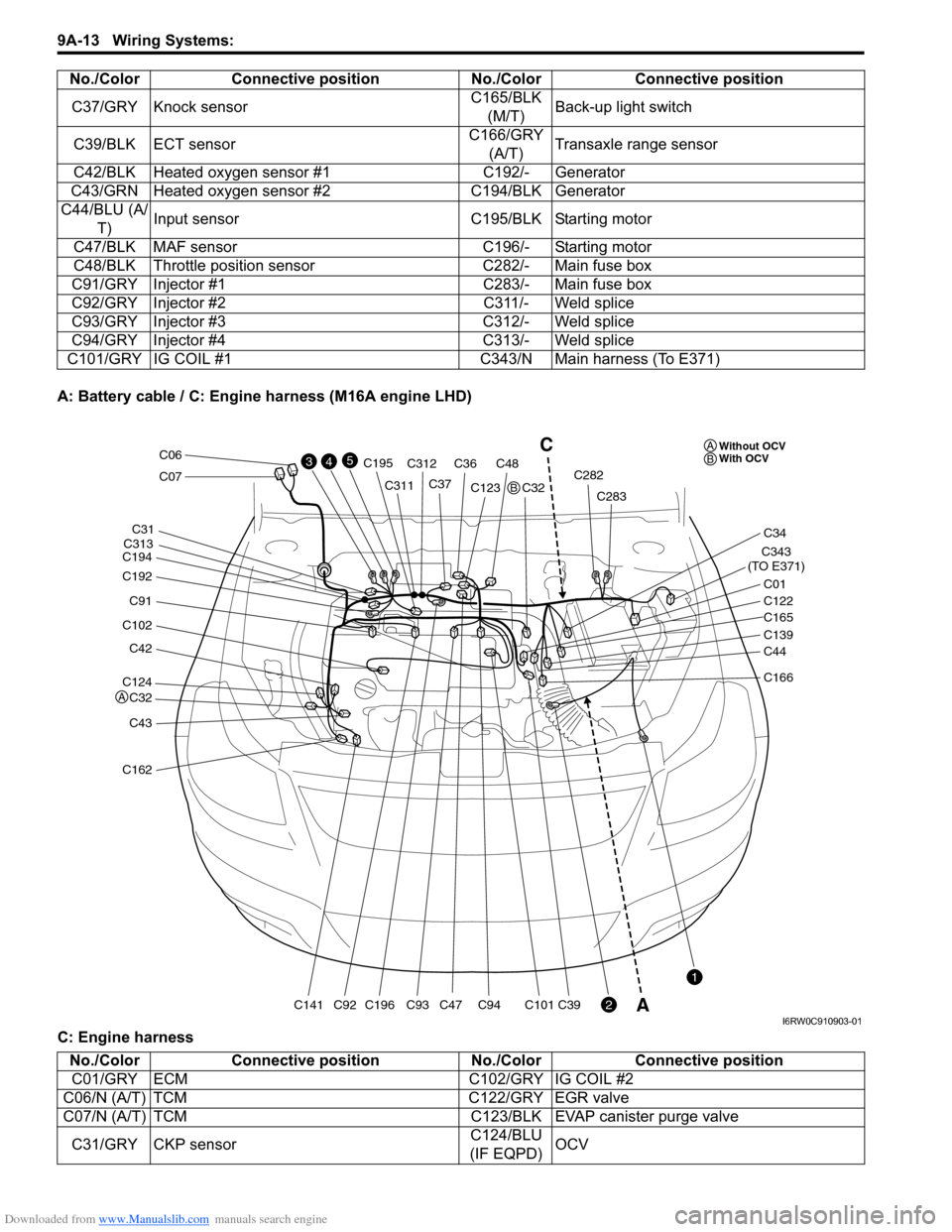
A: Battery cable / C: Engine harness (M16A engine LHD)
C: Engine harnessC37/GRY Knock sensorC165/BLK
(M/T)Back-up light switch
C39/BLK ECT sensorC166/GRY
(A/T)Transaxle range sensor
C42/BLK Heated oxygen sensor #1 C192/- Generator
C43/GRN Heated oxygen sensor #2 C194/BLK Generator
C44/BLU (A/
T)Input sensor C195/BLK Starting motor
C47/BLK MAF sensor C196/- Starting motor
C48/BLK Throttle position sensor C282/- Main fuse box
C91/GRY Injector #1 C283/- Main fuse box
C92/GRY Injector #2 C311/- Weld splice
C93/GRY Injector #3 C312/- Weld splice
C94/GRY Injector #4 C313/- Weld splice
C101/GRY IG COIL #1 C343/N Main harness (To E371)No./Color Connective position No./Color Connective position
C124
C32
C42
C102
C91
C192
C194
C43
C162
C141C196
C195
C93C94C101C39C92
C31
C311
C313C312
C36C48
C37C123
C47C32C282
C283
C343
(TO E371)
C01
C34
C07
C06
C122
C165
C139
C44
C166
43
2
1
5C
AWithout OCV
With OCV A
A
B
B
I6RW0C910903-01
No./Color Connective position No./Color Connective position
C01/GRY ECM C102/GRY IG COIL #2
C06/N (A/T) TCM C122/GRY EGR valve
C07/N (A/T) TCM C123/BLK EVAP canister purge valve
C31/GRY CKP sensorC124/BLU
(IF EQPD)OCV
Page 1181 of 1556
Downloaded from www.Manualslib.com manuals search engine Wiring Systems: 9A-14
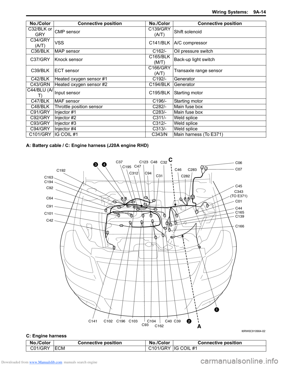
A: Battery cable / C: Engine harness (J20A engine RHD)
C: Engine harnessC32/BLK or
GRYCMP sensorC139/GRY
(A/T)Shift solenoid
C34/GRY
(A/T)VSS C141/BLK A/C compressor
C36/BLK MAP sensor C162/- Oil pressure switch
C37/GRY Knock sensorC165/BLK
(M/T)Back-up light switch
C39/BLK ECT sensorC166/GRY
(A/T)Transaxle range sensor
C42/BLK Heated oxygen sensor #1 C192/- Generator
C43/GRN Heated oxygen sensor #2 C194/BLK Generator
C44/BLU (A/
T)Input sensor C195/BLK Starting motor
C47/BLK MAF sensor C196/- Starting motor
C48/BLK Throttle position sensor C282/- Main fuse box
C91/GRY Injector #1 C283/- Main fuse box
C92/GRY Injector #2 C311/- Weld splice
C93/GRY Injector #3 C312/- Weld splice
C94/GRY Injector #4 C313/- Weld splice
C101/GRY IG COIL #1 C343/N Main harness (To E371)No./Color Connective position No./Color Connective position
C42
C101
C91
C64 C92
C194 C163
C141C102C196 C192
C195
C312
C93C104C103
C94C31C32
C40
C162
C39
C123C48C37
C47
C282
C283C46
C343
(TO E371)
C01
C45
C07
C06
C139 C44
C165
C166
3
2
1
4
A
C
I6RW0C910904-02
No./Color Connective position No./Color Connective position
C01/GRY ECM C101/GRY IG COIL #1
Page 1182 of 1556
Downloaded from www.Manualslib.com manuals search engine 9A-15 Wiring Systems:
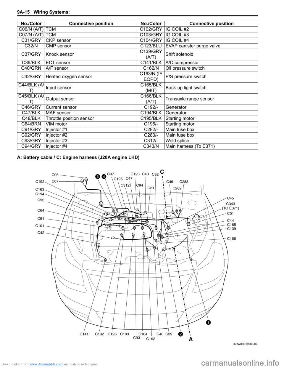
A: Battery cable / C: Engine harness (J20A engine LHD)C06/N (A/T) TCM C102/GRY IG COIL #2
C07/N (A/T) TCM C103/GRY IG COIL #3
C31/GRY CKP sensor C104/GRY IG COIL #4
C32/N CMP sensor C123/BLU EVAP canister purge valve
C37/GRY Knock sensorC139/GRY
(A/T)Shift solenoid
C39/BLK ECT sensor C141/BLK A/C compressor
C40/GRN A/F sensor C162/N Oil pressure switch
C42/GRY Heated oxygen sensorC163/N (IF
EQPD)P/S pressure switch
C44/BLK (A/
T)Input sensorC165/BLK
(M/T)Back-up light switch
C45/BLK (A/
T)Output sensorC166/BLK
(A/T)Transaxle range sensor
C46/GRY Current sensor C192/- Generator
C47/BLK MAF sensor C194/BLK Generator
C48/BLK Throttle position sensor C195/BLK Starting motor
C64/BRN VIM motor C196/- Starting motor
C91/GRY Injector #1 C282/- Main fuse box
C92/GRY Injector #2 C283/- Main fuse box
C93/GRY Injector #3 C312/- Weld splice
C94/GRY Injector #4 C343/N Main harness (To E371) No./Color Connective position No./Color Connective position
C42
C101
C91
C64 C92
C194 C163
C141C102C196 C192
C195
C312
C93C104C103
C94C31C32
C40
C162
C39
C123C48C37
C47
C282
C283C46
C343
(TO E371)
C01
C45
C07
C06
C139 C44
C165
C166
3
2
1
4C
A
I6RW0C910905-02