2006 SUZUKI SX4 Motor
[x] Cancel search: MotorPage 1005 of 1556
Downloaded from www.Manualslib.com manuals search engine Air Conditioning System: Automatic Type 7B-65
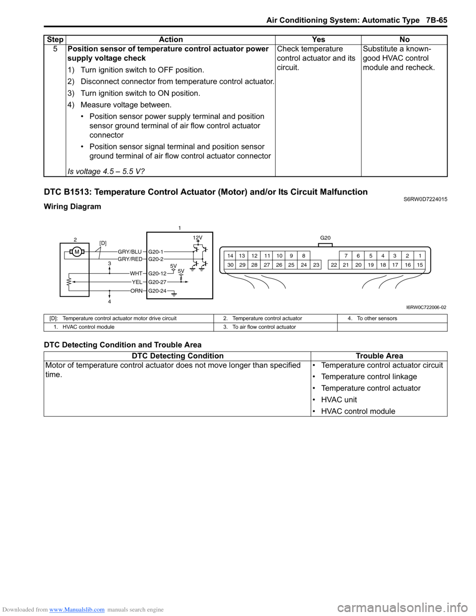
DTC B1513: Temperature Control Actuator (Motor) and/or Its Circuit MalfunctionS6RW0D7224015
Wiring Diagram
DTC Detecting Condition and Trouble Area5Position sensor of temperature control actuator power
supply voltage check
1) Turn ignition switch to OFF position.
2) Disconnect connector from temperature control actuator.
3) Turn ignition switch to ON position.
4) Measure voltage between.
• Position sensor power supply terminal and position
sensor ground terminal of air flow control actuator
connector
• Position sensor signal terminal and position sensor
ground terminal of air flow control actuator connector
Is voltage 4.5 – 5.5 V?Check temperature
control actuator and its
circuit.Substitute a known-
good HVAC control
module and recheck. Step Action Yes No
G20
1 2 3 4 5 6 7 8 9 10 11 12 13 14
15 16 17 18 19 20 21 24 23 22 25 26 27 28 29 30
GRY/BLUGRY/RED
5V5V
12V
ORN
WHT
YEL
G20-12
G20-27
G20-24
G20-1G20-2
2
[D]
3
41
I6RW0C722006-02
[D]: Temperature control actuator motor drive circuit 2. Temperature control actuator 4. To other sensors
1. HVAC control module 3. To air flow control actuator
DTC Detecting Condition Trouble Area
Motor of temperature control actuator does not move longer than specified
time.• Temperature control actuator circuit
• Temperature control linkage
• Temperature control actuator
• HVAC unit
• HVAC control module
Page 1006 of 1556
Downloaded from www.Manualslib.com manuals search engine 7B-66 Air Conditioning System: Automatic Type
DTC Troubleshooting
Step Action Yes No
1Was “Air Conditioning System Check” performed?Go to Step 2. Go to “Air Conditioning
System Check”.
2DTC check
1) Connect scan tool to DLC with ignition switch turned
OFF.
2) Turn ignition switch to ON position and check DTC.
Is DTC B1511 detected together?Go to “DTC B1511:
Temperature Control
Actuator (Position
Sensor) and/or Its
Circuit Malfunction”.Go to Step 3.
3Visual Check
Check if there is any obstruction in operating range of
actuator linkage and if actuator linkage operates smoothly.
Is it in good condition?Go to Step 4. Obstruction in operating
range of actuator
linkage, actuator linkage
faulty and/or internal
fault of HVAC unit.
4Wire harness check
1) Turn ignition switch to OFF position.
2) Disconnect connectors from temperature control
actuator and HVAC control module.
3) Check for proper connection to actuator motor drive
circuit terminals of temperature control actuator and
HVAC control module connectors.
4) If OK, check that actuator motor drive circuit of
temperature control actuator is as follows.
• Wiring harness resistance of each actuator motor
drive circuit is less than 3 Ω
• Insulation resistance of each actuator motor drive
circuit is infinity between temperature control actuator
connector and vehicle body ground
• Circuit voltage of each actuator motor drive circuit is 0
– 1 V with ignition switch turned ON
Are they in good condition?Go to Step 5. Actuator motor drive
circuit(s) is open, short
or high resistance.
5Wire harness check
Check position sensor circuit of temperature control actuator
for condition referring to Step 2 of “DTC B1511: Temperature
Control Actuator (Position Sensor) and/or Its Circuit
Malfunction”.
Is it in good condition?Go to Step 6. Repair or replace.
6Temperature control actuator check
1) Check temperature control actuator for performance
referring to “Temperature Control Actuator and Its Circuit
Inspection”.
Is it in good condition?Substitute a known-
good HVAC control
module and recheck.Replace temperature
control actuator.
Page 1007 of 1556
Downloaded from www.Manualslib.com manuals search engine Air Conditioning System: Automatic Type 7B-67
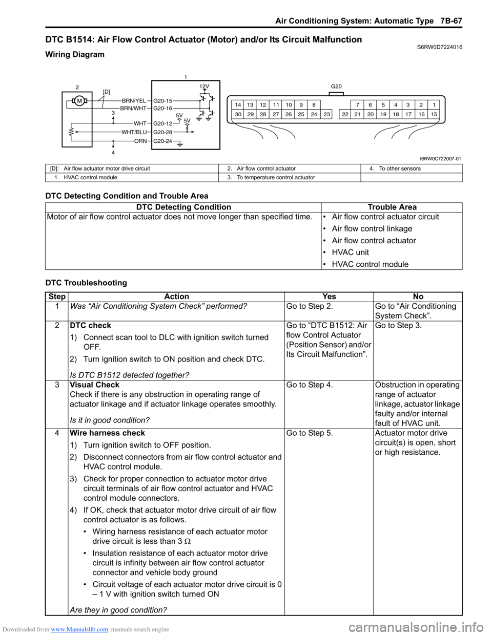
DTC B1514: Air Flow Control Actuator (Motor) and/or Its Circuit MalfunctionS6RW0D7224016
Wiring Diagram
DTC Detecting Condition and Trouble Area
DTC Troubleshooting
G20
1 2 3 4 5 6 7 8 9 10 11 12 13 14
15 16 17 18 19 20 21 24 23 22 25 26 27 28 29 30
BRN/YELBRN/WHT
5V5V
12V
ORN
WHTG20-12
G20-28
G20-24
G20-15G20-16
WHT/BLU 2
3
41
[D]
I6RW0C722007-01
[D]: Air flow actuator motor drive circuit 2. Air flow control actuator 4. To other sensors
1. HVAC control module 3. To temperature control actuator
DTC Detecting Condition Trouble Area
Motor of air flow control actuator does not move longer than specified time. • Air flow control actuator circuit
• Air flow control linkage
• Air flow control actuator
• HVAC unit
• HVAC control module
Step Action Yes No
1Was “Air Conditioning System Check” performed?Go to Step 2. Go to “Air Conditioning
System Check”.
2DTC check
1) Connect scan tool to DLC with ignition switch turned
OFF.
2) Turn ignition switch to ON position and check DTC.
Is DTC B1512 detected together?Go to “DTC B1512: Air
flow Control Actuator
(Position Sensor) and/or
Its Circuit Malfunction”.Go to Step 3.
3Visual Check
Check if there is any obstruction in operating range of
actuator linkage and if actuator linkage operates smoothly.
Is it in good condition?Go to Step 4. Obstruction in operating
range of actuator
linkage, actuator linkage
faulty and/or internal
fault of HVAC unit.
4Wire harness check
1) Turn ignition switch to OFF position.
2) Disconnect connectors from air flow control actuator and
HVAC control module.
3) Check for proper connection to actuator motor drive
circuit terminals of air flow control actuator and HVAC
control module connectors.
4) If OK, check that actuator motor drive circuit of air flow
control actuator is as follows.
• Wiring harness resistance of each actuator motor
drive circuit is less than 3 Ω
• Insulation resistance of each actuator motor drive
circuit is infinity between air flow control actuator
connector and vehicle body ground
• Circuit voltage of each actuator motor drive circuit is 0
– 1 V with ignition switch turned ON
Are they in good condition?Go to Step 5. Actuator motor drive
circuit(s) is open, short
or high resistance.
Page 1017 of 1556
Downloaded from www.Manualslib.com manuals search engine Air Conditioning System: Automatic Type 7B-77
G20-8 BLU/WHTElectric load signal for
blower motor10 – 14 V• Ignition switch turned ON, blower speed selector
OFF or 1st position
• Ignition switch turned ON, blower speed selector
from 1st to 2nd position
0 – 2 V• Ignition switch turned ON, blower speed selector
between 3rd and HIGH position
• Ignition switch turned ON, blower speed selector
from 3rd to 2nd position
G20-9 WHT/BLKEvaporator temperature
sensor signalApprox. 2.6 VIgnition switch turned ON, evaporator temperature 0
°C (32 °F)
Approx. 1.7 VIgnition switch turned ON, evaporator temperature
15 °C (59 °F)
Approx. 1.0 VIgnition switch turned ON, evaporator temperature
30 °C (86 °F)
G20-10 PNK/BLKInside air temperature
sensor signalApprox. 2.5 VIgnition switch turned ON, room temperature 25 °C
(77 °F)
Approx. 3.7 VIgnition switch turned ON, room temperature 0 °C
(32 °F)
G20-11 — — —
G20-12 WHTOutput of 5 V power
source for air flow control
actuator position sensor
and temperature control
actuator position sensor4 – 6 V Ignition switch turned ON
G20-13 YELSerial communication line
of BCMRefer to “Reference waveform No. 2: Automatic Type”.
G20-14 — — — —
G20-15 BRN/YELAir flow control actuator
(FACE)10 – 14 VIgnition switch turned ON, air flow control actuator is
working in operation from “DEF” to “FACE” position
0 – 1 VIgnition switch turned ON, except the above
condition
G20-16 BRN/WHTAir flow control actuator
(DEF)10 – 14 VIgnition switch turned ON, air flow control actuator is
working in operation from “FACE” to “DEF” position
0 – 1 VIgnition switch turned ON, except the above
condition
G20-17 GRNAir intake actuator
(FRESH AIR)0 – 1 VIgnition switch turned ON, air intake selector “FRE”
position
10 – 14 VIgnition switch turned ON, air intake selector “REC”
position
G20-18 REDAir intake actuator
(RECIRCULATION AIR)0 – 1 VIgnition switch turned ON, air intake selector “REC”
position
10 – 14 VIgnition switch turned ON, air intake selector “FRE”
position
G20-19 GRN/REDAir intake actuator (MIX
AIR)10 – 14 VIgnition switch turned ON, air intake selector “FRE”
or “REC” position
0 – 1 VIgnition switch turned ON, air intake selector is
working in operation from “FRE” to “REC” or “REC”
to “FRE” position
G20-20 — — — —
G20-21 GRN/WHT A/C switch signal Refer to “Reference waveform No. 1: Automatic Type”.
G20-22 RED/BLK Electric power source 10 – 14 V Ignition switch turned ON
G20-23 BLK/ORNGround for HVAC control
moduleBelow 0.5 V Ignition switch turned ON
G20-24 ORN Ground for sensors Below 0.5 V Ignition switch turned ON Terminal Wire Color CircuitNormal
Vo l ta g eCondition
Page 1018 of 1556
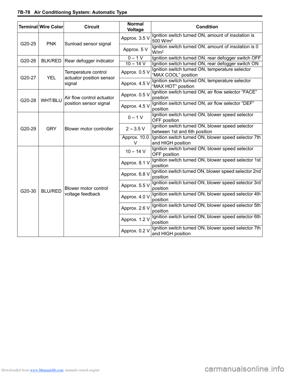
Downloaded from www.Manualslib.com manuals search engine 7B-78 Air Conditioning System: Automatic Type
G20-25 PNK Sunload sensor signalApprox. 3.5 VIgnition switch turned ON, amount of insolation is
500 W/m2
Approx. 5 VIgnition switch turned ON, amount of insolation is 0
W/m2
G20-26 BLK/RED Rear defogger indicator0 – 1 V Ignition switch turned ON, rear defogger switch OFF
10 – 14 V Ignition switch turned ON, rear defogger switch ON
G20-27 YELTemperature control
actuator position sensor
signalApprox. 0.5 VIgnition switch turned ON, temperature selector
“MAX COOL” position
Approx. 4.5 VIgnition switch turned ON, temperature selector
“MAX HOT” position
G20-28 WHT/BLUAir flow control actuator
position sensor signalApprox. 0.5 VIgnition switch turned ON, air flow selector “FACE”
position
Approx. 4.5 VIgnition switch turned ON, air flow selector “DEF”
position
G20-29 GRY Blower motor controller0 – 1 VIgnition switch turned ON, blower speed selector
OFF position
2 – 3.5 VIgnition switch turned ON, blower speed selector
between 1st and 6th position
Approx. 10.0
VIgnition switch turned ON, blower speed selector 7th
and HIGH position
G20-30 BLU/REDBlower motor control
voltage feedback10 – 14 VIgnition switch turned ON, blower speed selector
OFF position
Approx. 8.1 VIgnition switch turned ON, blower speed selector 1st
position
Approx. 6.8 VIgnition switch turned ON, blower speed selector 2nd
position
Approx. 5.5 VIgnition switch turned ON, blower speed selector 3rd
position
Approx. 4.0 VIgnition switch turned ON, blower speed selector 4th
position
Approx. 2.6 VIgnition switch turned ON, blower speed selector 5th
position
Approx. 1.2 VIgnition switch turned ON, blower speed selector 6th
position
Approx. 0.2 VIgnition switch turned ON, blower speed selector 7th
and HIGH position Terminal Wire Color CircuitNormal
Vo l ta g eCondition
Page 1020 of 1556
Downloaded from www.Manualslib.com manuals search engine 7B-80 Air Conditioning System: Automatic Type
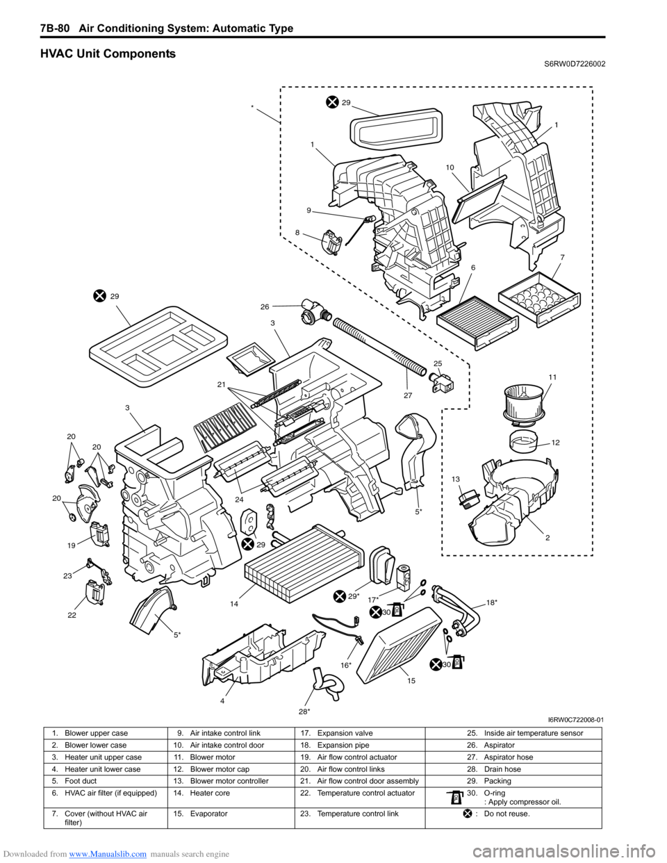
HVAC Unit ComponentsS6RW0D7226002
1
10
1
29
9
8
3
29
21
3
20 20
20
19
23
22
5*
4
28*15 16*
30
29*
30
17*
18*2 1312 11
5*
26
2725
1424
29
67
*
I6RW0C722008-01
1. Blower upper case 9. Air intake control link 17. Expansion valve 25. Inside air temperature sensor
2. Blower lower case 10. Air intake control door 18. Expansion pipe 26. Aspirator
3. Heater unit upper case 11. Blower motor 19.Air flow control actuator 27. Aspirator hose
4. Heater unit lower case 12. Blower motor cap 20. Air flow control links 28. Drain hose
5. Foot duct 13. Blower motor controller 21. Air flow control door assembly 29. Packing
6. HVAC air filter (if equipped) 14. Heater core 22. Temperature control actuator 30. O-ring
: Apply compressor oil.
7. Cover (without HVAC air
filter)15. Evaporator 23. Temperature control link : Do not reuse.
Page 1024 of 1556
Downloaded from www.Manualslib.com manuals search engine 7B-84 Air Conditioning System: Automatic Type
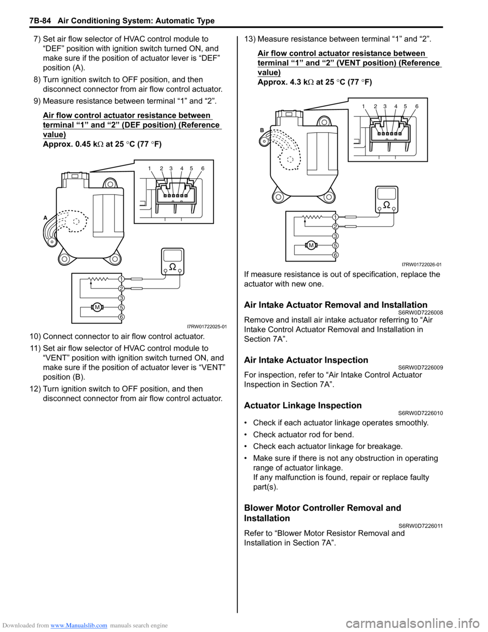
7) Set air flow selector of HVAC control module to
“DEF” position with ignition switch turned ON, and
make sure if the position of actuator lever is “DEF”
position (A).
8) Turn ignition switch to OFF position, and then
disconnect connector from air flow control actuator.
9) Measure resistance between terminal “1” and “2”.
Air flow control actuator resistance between
terminal “1” and “2” (DEF position) (Reference
value)
Approx. 0.45 kΩ at 25 °C (77 °F)
10) Connect connector to air flow control actuator.
11) Set air flow selector of HVAC control module to
“VENT” position with ignition switch turned ON, and
make sure if the position of actuator lever is “VENT”
position (B).
12) Turn ignition switch to OFF position, and then
disconnect connector from air flow control actuator.13) Measure resistance between terminal “1” and “2”.
Air flow control actuator resistance between
terminal “1” and “2” (VENT position) (Reference
value)
Approx. 4.3 kΩ at 25 °C (77 °F)
If measure resistance is out of specification, replace the
actuator with new one.
Air Intake Actuator Removal and InstallationS6RW0D7226008
Remove and install air intake actuator referring to “Air
Intake Control Actuator Removal and Installation in
Section 7A”.
Air Intake Actuator InspectionS6RW0D7226009
For inspection, refer to “Air Intake Control Actuator
Inspection in Section 7A”.
Actuator Linkage InspectionS6RW0D7226010
• Check if each actuator linkage operates smoothly.
• Check actuator rod for bend.
• Check each actuator linkage for breakage.
• Make sure if there is not any obstruction in operating
range of actuator linkage.
If any malfunction is found, repair or replace faulty
part(s).
Blower Motor Controller Removal and
Installation
S6RW0D7226011
Refer to “Blower Motor Resistor Removal and
Installation in Section 7A”.
123456
6
M5
3
2
1 A
I7RW01722025-01
123456
6
M5
3
2
1 B
I7RW01722026-01
Page 1025 of 1556
Downloaded from www.Manualslib.com manuals search engine Air Conditioning System: Automatic Type 7B-85
Blower Motor Controller InspectionS6RW0D7226012
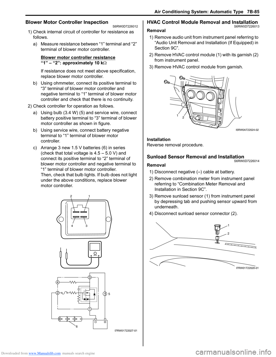
1) Check internal circuit of controller for resistance as
follows.
a) Measure resistance between “1” terminal and “2”
terminal of blower motor controller.
Blower motor controller resistance
“1” – “2”: approximately 10 kΩ
If resistance does not meet above specification,
replace blower motor controller.
b) Using ohmmeter, connect its positive terminal to
“3” terminal of blower motor controller and
negative terminal to “1” terminal of blower motor
controller and check that there is no continuity.
2) Check controller for operation as follows.
a) Using bulb (3.4 W) (5) and service wire, connect
battery positive terminal to “3” terminal of blower
motor controller as shown in figure.
b) Using service wire, connect battery negative
terminal to “1” terminal of blower motor
controller.
c) Arrange 3 new 1.5 V batteries (6) in series
(check that total voltage is 4.5 – 5.0 V) and
connect its positive terminal to “2” terminal of
blower motor controller and negative terminal to
“1” terminal of blower motor controller.
Then, check that bulb lights. If bulb does not light
under the above conditions, replace blower
motor controller.
HVAC Control Module Removal and InstallationS6RW0D7226013
Removal
1) Remove audio unit from instrument panel referring to
“Audio Unit Removal and Installation (If Equipped) in
Section 9C”.
2) Remove HVAC control module (1) with its garnish (2)
from instrument panel.
3) Remove HVAC control module from garnish.
Installation
Reverse removal procedure.
Sunload Sensor Removal and InstallationS6RW0D7226014
Removal
1) Disconnect negative (–) cable at battery.
2) Remove combination meter from instrument panel
referring to “Combination Meter Removal and
Installation in Section 9C”.
3) Remove sunload sensor (1) from instrument panel
by depressing tab and pushing sensor upward from
underneath.
4) Disconnect sunload sensor connector (2).
21
43
3
1 2 4
5
6I7RW01722027-01
12
I5RW0A722024-02
1
2
I7RW01722028-01