Page 1304 of 1556
Downloaded from www.Manualslib.com manuals search engine 9A-137 Wiring Systems:
B
P/S
Cont.M
3
E377
E378
E61
M
REDBLK
E12
ECM
"A-5"
BRN
1211
12
BRN
6
E11
RED/BLU
5
RB
14
RED/BLU
G211
DLC
4
BLKBLK
B
B
J/C Motor
G309
BLU
BLU
E382
G33419
E382
G33412
E371
C3438
BLK/ORN
5
J/B
15ADOME
37
G2715
WHT/RED
BLK/ORN
7
16
B
B
J/C
G308
BLK/ORN
1114
WHT/RED
BLK
BLUB
WHTRED
RW"A-8"
14
6
BCM
BLU
A
A
J/C
G308
(CAN) IF EQPD
4
RHD
LHD
Except M16A engine M/T
M16A engine M/T
Except Taiwan
Taiwan A
C
5
D
BCDEF
1
2AB2
1AB
I6RW0C910A06-01
Page 1356 of 1556
Downloaded from www.Manualslib.com manuals search engine 9C-4 Instrumentation / Driver Info. / Horn:
Schematic and Routing Diagram
Combination Meter Circuit DiagramS6RW0D9302001
7
6
5
4G241-99
G241-5
1
2
11
G241-1323
G241-31
G241-263
G241-16
G241-2212
G241-2513
G241-13
8 17
1514
20
G241-32
G241-69
16
18
19
G241-2121
G241-7 G241-10 10
10
G241-1922
I6RW0D930002-01
1. DOME fuse 9. 4WD control module (if equipped) 17. CAN driver
2. METER fuse 10. CAN junction connector 18. Stepper motor and LED output driver
3. Combination switch 11. SDM 19. A/T shift position indicator (“P”, “R”, “N”, “D”, “3”, “2” and “L”)
4. Tachometer 12. Combination switch (high beam) 20. Combination meter
5. Speedometer 13. P/S control module 21. Combination switch (rear fog light)
6. Fuel meter 14. CPU 22. Headlight leveling control module (if equipped)
7. ECT meter 15. Power supply 23. Illumination cancel switch (if equipped)
8. ODO-TRIP 16. Interface circuit
Page 1375 of 1556
Downloaded from www.Manualslib.com manuals search engine Wipers / Washers: 9D-1
Body, Cab and Accessories
Wipers / Washers
Diagnostic Information and Procedures
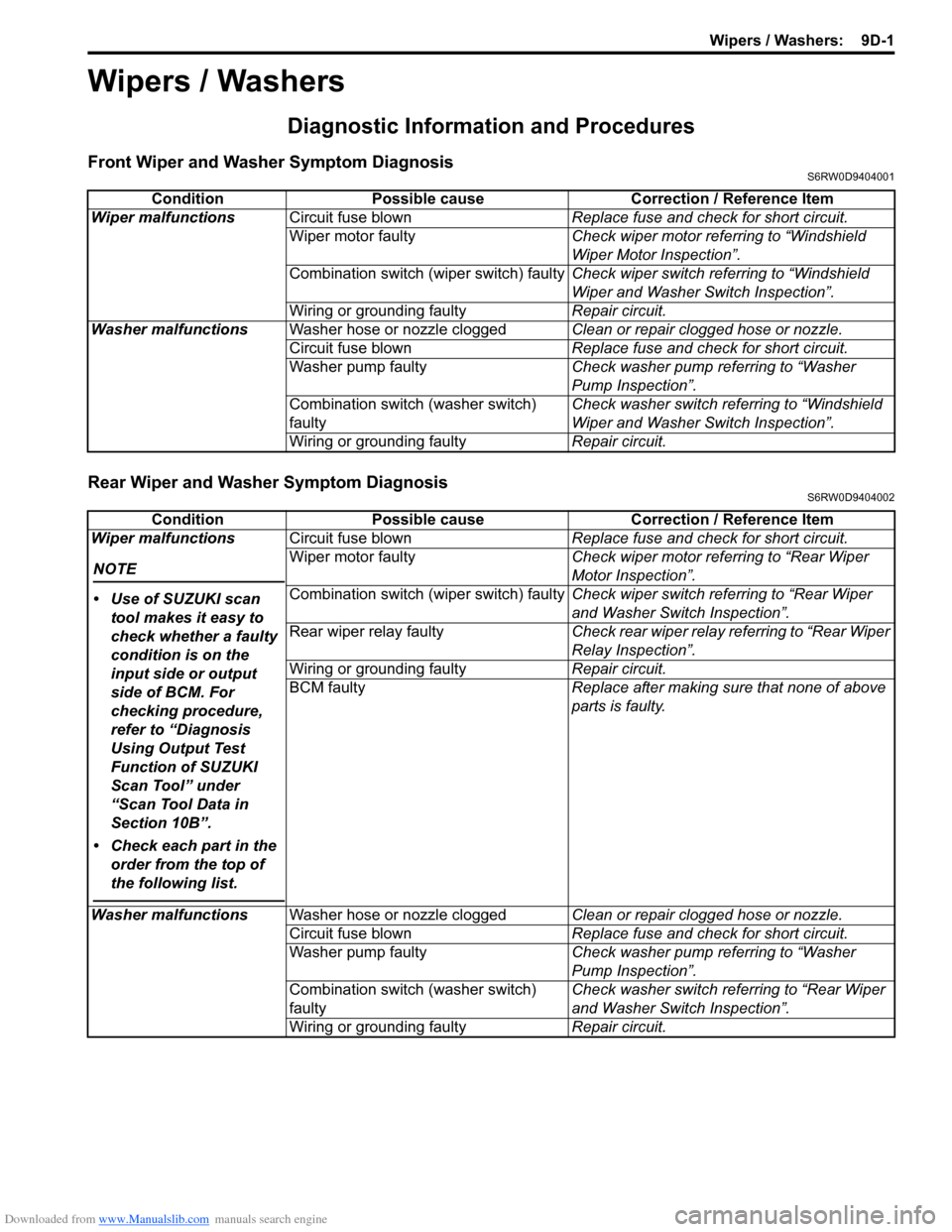
Front Wiper and Washer Symptom DiagnosisS6RW0D9404001
Rear Wiper and Washer Symptom DiagnosisS6RW0D9404002
Condition Possible cause Correction / Reference Item
Wiper malfunctionsCircuit fuse blownReplace fuse and check for short circuit.
Wiper motor faultyCheck wiper motor referring to “Windshield
Wiper Motor Inspection”.
Combination switch (wiper switch) faultyCheck wiper switch referring to “Windshield
Wiper and Washer Switch Inspection”.
Wiring or grounding faultyRepair circuit.
Washer malfunctionsWasher hose or nozzle cloggedClean or repair clogged hose or nozzle.
Circuit fuse blownReplace fuse and check for short circuit.
Washer pump faultyCheck washer pump referring to “Washer
Pump Inspection”.
Combination switch (washer switch)
faultyCheck washer switch referring to “Windshield
Wiper and Washer Switch Inspection”.
Wiring or grounding faultyRepair circuit.
Condition Possible cause Correction / Reference Item
Wiper malfunctions
NOTE
• Use of SUZUKI scan
tool makes it easy to
check whether a faulty
condition is on the
input side or output
side of BCM. For
checking procedure,
refer to “Diagnosis
Using Output Test
Function of SUZUKI
Scan Tool” under
“Scan Tool Data in
Section 10B”.
• Check each part in the
order from the top of
the following list.
Circuit fuse blownReplace fuse and check for short circuit.
Wiper motor faultyCheck wiper motor referring to “Rear Wiper
Motor Inspection”.
Combination switch (wiper switch) faultyCheck wiper switch referring to “Rear Wiper
and Washer Switch Inspection”.
Rear wiper relay faultyCheck rear wiper relay referring to “Rear Wiper
Relay Inspection”.
Wiring or grounding faultyRepair circuit.
BCM faultyReplace after making sure that none of above
parts is faulty.
Washer malfunctionsWasher hose or nozzle cloggedClean or repair clogged hose or nozzle.
Circuit fuse blownReplace fuse and check for short circuit.
Washer pump faultyCheck washer pump referring to “Washer
Pump Inspection”.
Combination switch (washer switch)
faultyCheck washer switch referring to “Rear Wiper
and Washer Switch Inspection”.
Wiring or grounding faultyRepair circuit.
Page 1376 of 1556
Downloaded from www.Manualslib.com manuals search engine 9D-2 Wipers / Washers:
Repair Instructions
Wipers and Washers ComponentsS6RW0D9406001
115
6
(b)
(a) 1 1
(b)
2
1314
14[A]
14
1215
(c)
(b)
(a)
32
4
710
10
10 11118
16
9
16
I7RW01940001-03
1. Windshield wiper blade 8. Washer pump for rear washer 15. Windshield wiper bolt
:Tighten bolts in specified order.
2. Windshield wiper arm 9. Washer tank 16. Washer tank bolt
3. Windshield wiper motor 10. Washer hose[A]: Junction block viewed from relay
side
4. Windshield wiper link 11. Washer nozzle : 18 N⋅m (1.8 kgf-m, 13.0 lb-ft)
Page 1377 of 1556
Downloaded from www.Manualslib.com manuals search engine Wipers / Washers: 9D-3
Washer Tank and Washer Pump Removal and
Installation
S6RW0D9406002
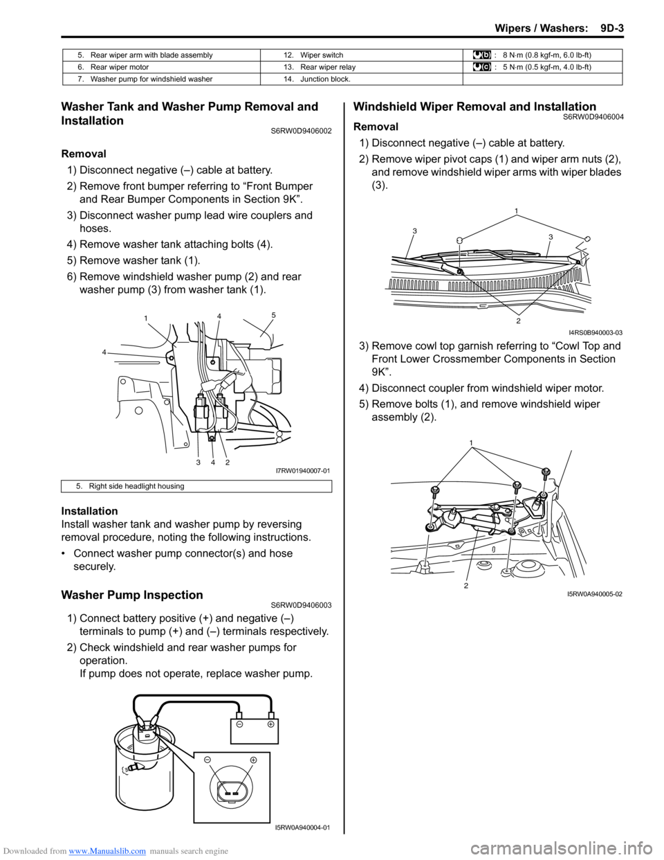
Removal
1) Disconnect negative (–) cable at battery.
2) Remove front bumper referring to “Front Bumper
and Rear Bumper Components in Section 9K”.
3) Disconnect washer pump lead wire couplers and
hoses.
4) Remove washer tank attaching bolts (4).
5) Remove washer tank (1).
6) Remove windshield washer pump (2) and rear
washer pump (3) from washer tank (1).
Installation
Install washer tank and washer pump by reversing
removal procedure, noting the following instructions.
• Connect washer pump connector(s) and hose
securely.
Washer Pump InspectionS6RW0D9406003
1) Connect battery positive (+) and negative (–)
terminals to pump (+) and (–) terminals respectively.
2) Check windshield and rear washer pumps for
operation.
If pump does not operate, replace washer pump.
Windshield Wiper Removal and InstallationS6RW0D9406004
Removal
1) Disconnect negative (–) cable at battery.
2) Remove wiper pivot caps (1) and wiper arm nuts (2),
and remove windshield wiper arms with wiper blades
(3).
3) Remove cowl top garnish referring to “Cowl Top and
Front Lower Crossmember Components in Section
9K”.
4) Disconnect coupler from windshield wiper motor.
5) Remove bolts (1), and remove windshield wiper
assembly (2).
5. Rear wiper arm with blade assembly 12. Wiper switch : 8 N⋅m (0.8 kgf-m, 6.0 lb-ft)
6. Rear wiper motor 13. Rear wiper relay : 5 N⋅m (0.5 kgf-m, 4.0 lb-ft)
7. Washer pump for windshield washer 14. Junction block.
5. Right side headlight housing
1
4
34245
I7RW01940007-01
I5RW0A940004-01
1
3 3
2
I4RS0B940003-03
21I5RW0A940005-02
Page 1378 of 1556
Downloaded from www.Manualslib.com manuals search engine 9D-4 Wipers / Washers:
Installation
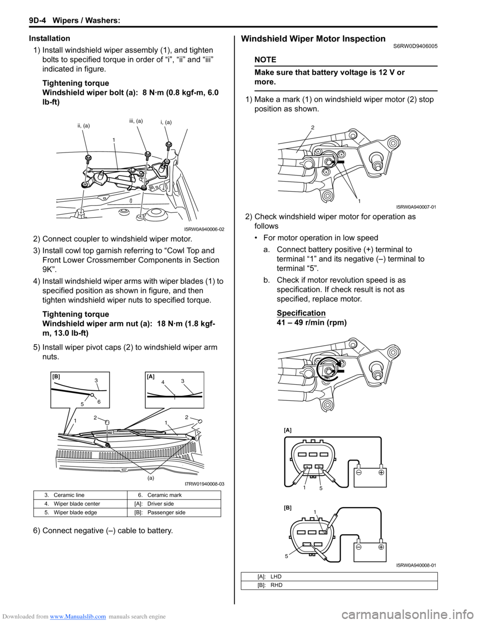
1) Install windshield wiper assembly (1), and tighten
bolts to specified torque in order of “i”, “ii” and “iii”
indicated in figure.
Tightening torque
Windshield wiper bolt (a): 8 N·m (0.8 kgf-m, 6.0
lb-ft)
2) Connect coupler to windshield wiper motor.
3) Install cowl top garnish referring to “Cowl Top and
Front Lower Crossmember Components in Section
9K”.
4) Install windshield wiper arms with wiper blades (1) to
specified position as shown in figure, and then
tighten windshield wiper nuts to specified torque.
Tightening torque
Windshield wiper arm nut (a): 18 N·m (1.8 kgf-
m, 13.0 lb-ft)
5) Install wiper pivot caps (2) to windshield wiper arm
nuts.
6) Connect negative (–) cable to battery.Windshield Wiper Motor InspectionS6RW0D9406005
NOTE
Make sure that battery voltage is 12 V or
more.
1) Make a mark (1) on windshield wiper motor (2) stop
position as shown.
2) Check windshield wiper motor for operation as
follows
• For motor operation in low speed
a. Connect battery positive (+) terminal to
terminal “1” and its negative (–) terminal to
terminal “5”.
b. Check if motor revolution speed is as
specification. If check result is not as
specified, replace motor.
Specification
41 – 49 r/min (rpm)
3. Ceramic line 6. Ceramic mark
4. Wiper blade center [A]: Driver side
5. Wiper blade edge [B]: Passenger side
ii, (a)iii, (a)
1i, (a)
I5RW0A940006-02
2
23
41 1
(a)
3
56[A] [B]
I7RW01940008-03
[A]: LHD
[B]: RHD
2
1
I5RW0A940007-01
[A]
[B]
1
5
1
5
I5RW0A940008-01
Page 1379 of 1556
Downloaded from www.Manualslib.com manuals search engine Wipers / Washers: 9D-5
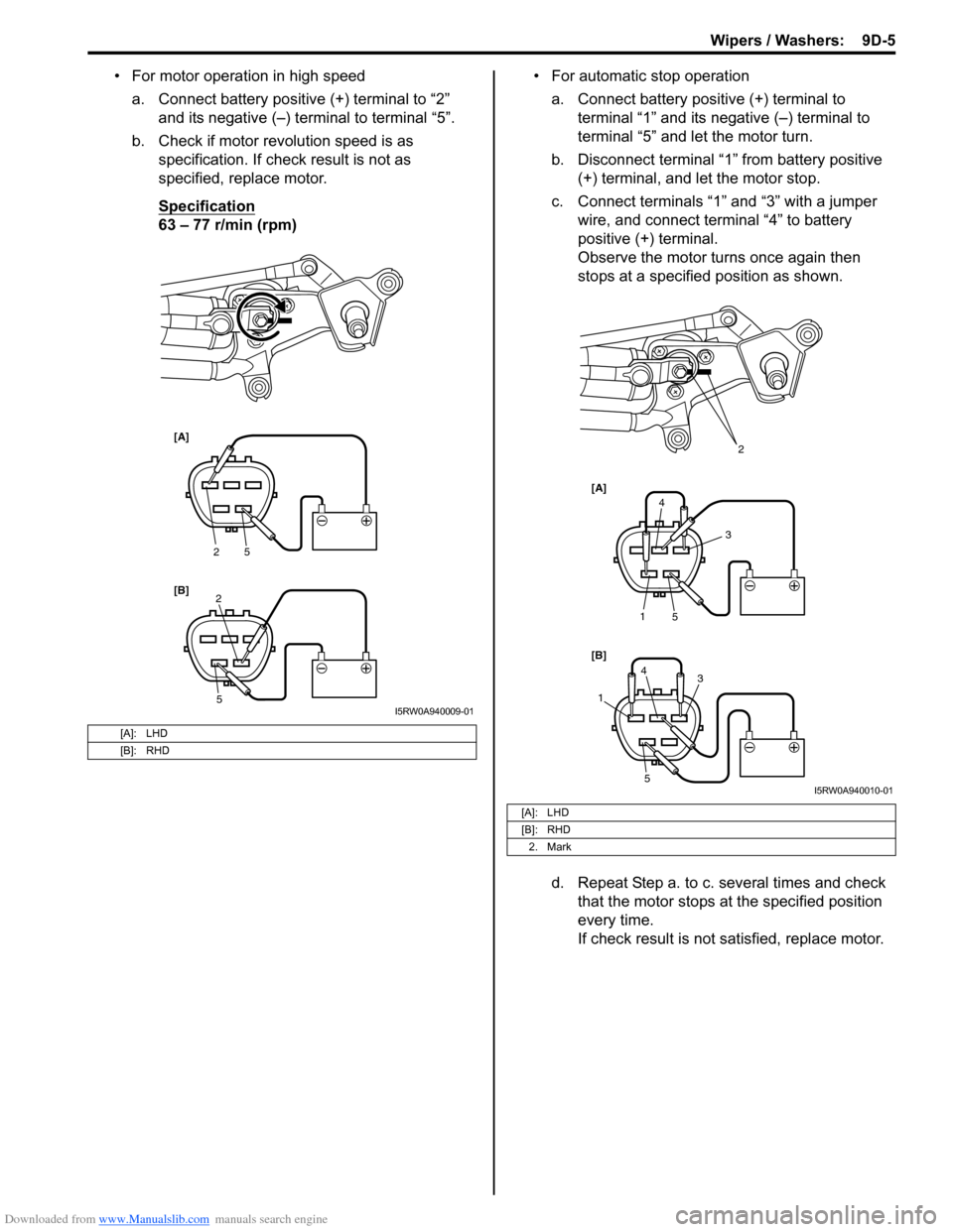
• For motor operation in high speed
a. Connect battery positive (+) terminal to “2”
and its negative (–) terminal to terminal “5”.
b. Check if motor revolution speed is as
specification. If check result is not as
specified, replace motor.
Specification
63 – 77 r/min (rpm)• For automatic stop operation
a. Connect battery positive (+) terminal to
terminal “1” and its negative (–) terminal to
terminal “5” and let the motor turn.
b. Disconnect terminal “1” from battery positive
(+) terminal, and let the motor stop.
c. Connect terminals “1” and “3” with a jumper
wire, and connect terminal “4” to battery
positive (+) terminal.
Observe the motor turns once again then
stops at a specified position as shown.
d. Repeat Step a. to c. several times and check
that the motor stops at the specified position
every time.
If check result is not satisfied, replace motor.
[A]: LHD
[B]: RHD
[A]
[B]
2
5
5 2
I5RW0A940009-01
[A]: LHD
[B]: RHD
2. Mark
[A]
[B]
5 1
4
3
4
5
13
2
I5RW0A940010-01
Page 1380 of 1556
Downloaded from www.Manualslib.com manuals search engine 9D-6 Wipers / Washers:
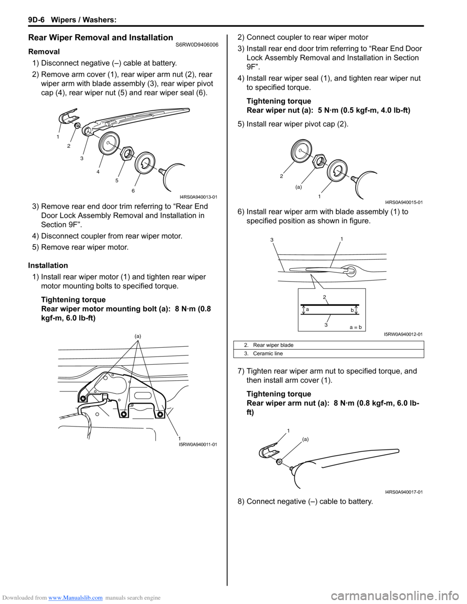
Rear Wiper Removal and InstallationS6RW0D9406006
Removal
1) Disconnect negative (–) cable at battery.
2) Remove arm cover (1), rear wiper arm nut (2), rear
wiper arm with blade assembly (3), rear wiper pivot
cap (4), rear wiper nut (5) and rear wiper seal (6).
3) Remove rear end door trim referring to “Rear End
Door Lock Assembly Removal and Installation in
Section 9F”.
4) Disconnect coupler from rear wiper motor.
5) Remove rear wiper motor.
Installation
1) Install rear wiper motor (1) and tighten rear wiper
motor mounting bolts to specified torque.
Tightening torque
Rear wiper motor mounting bolt (a): 8 N·m (0.8
kgf-m, 6.0 lb-ft)2) Connect coupler to rear wiper motor
3) Install rear end door trim referring to “Rear End Door
Lock Assembly Removal and Installation in Section
9F”.
4) Install rear wiper seal (1), and tighten rear wiper nut
to specified torque.
Tightening torque
Rear wiper nut (a): 5 N·m (0.5 kgf-m, 4.0 lb-ft)
5) Install rear wiper pivot cap (2).
6) Install rear wiper arm with blade assembly (1) to
specified position as shown in figure.
7) Tighten rear wiper arm nut to specified torque, and
then install arm cover (1).
Tightening torque
Rear wiper arm nut (a): 8 N·m (0.8 kgf-m, 6.0 lb-
ft)
8) Connect negative (–) cable to battery.
1
2
3
4
5
6
I4RS0A940013-01
1 (a)I5RW0A940011-01
2. Rear wiper blade
3. Ceramic line
2
1 (a)
I4RS0A940015-01
3 2a = b a
b
1
3
I5RW0A940012-01
1
(a)
I4RS0A940017-01