2006 SUZUKI SX4 remove seats
[x] Cancel search: remove seatsPage 329 of 1556

Downloaded from www.Manualslib.com manuals search engine Engine Mechanical: 1D-47
Cylinder Head InspectionS6RW0D1406029
• Remove all carbon deposits from combustion
chambers.
NOTE
Do not use any sharp-edged tool to scrape
off carbon deposits. Be careful not to scuff or
nick metal surfaces when decarbonizing. The
same applies to valves and valve seats, too.
• Check cylinder head for cracks on intake and exhaust
ports, combustion chambers, and head surface. Using
a straightedge and thickness gauge, check flatness of
gasketed surface at a total of 6 locations. If distortion
limit is exceeded, correct gasketed surface with a
surface plate and abrasive paper of about #400
(Waterproof silicon carbide abrasive paper): place
abrasive paper on and over surface plate, and rub
gasketed surface against paper to grind off high spots.
Should this fail to reduce thickness gauge readings to
within limit, replace cylinder head.
Leakage of combustion gases from this gasketed joint
is often due to warped gasketed surface: such
leakage results in reduced power output.Distortion for cylinder head surface on piston side
Limit: 0.03 mm (0.001 in.)
• Distortion of manifold seating faces:
Check seating faces of cylinder head for manifolds,
using a straightedge and thickness gauge, in order to
determine whether these faces should be corrected or
cylinder head replaced.
Distortion for cylinder head surface on intake and
exhaust manifold
Limit: 0.05 mm (0.002 in.)
I2RH0B140105-01
I2RH0B140106-01
I2RH0B140107-01
Page 475 of 1556

Downloaded from www.Manualslib.com manuals search engine Wheels and Tires: 2D-6
Wheel (with Tire) Removal and InstallationS6RW0D2406003
Removal
CAUTION!
Never use heat to loosen tight wheel because
the application of heat to wheel causes the
wheel life shorter and the wheel bearing
damage.
1) Loosen wheel nuts by approximately 180° (half a
rotation).
2) Hoist vehicle.
3) Make sure that the vehicle will not fall off by trying to
move vehicle body in both ways.
4) Remove wheel nuts except one.
5) Support the wheel and/or tire not to drop the wheel
and then remove the nut left with the wheel.
Installation
For installation, reverse removal procedure, noting the
following.
• Wheel nuts must be tightened in sequence and to
specified torque to avoid bending wheel or brake disc
or drum as shown in the figure.
NOTE
Before installing wheels, remove any build-
up of corrosion on wheel mounting surface
and brake disc or drum mounting surface by
scraping and wire brushing. Installing wheels
without good metal-to-metal contact at
mounting surfaces can cause wheel bolts to
loosen, which can later allow a wheel to
come off while vehicle is moving.
Tightening order
“1” – “2” – “3” – “4” – “5”
Tightening torque
Wheel nut (a): 85 N·m (8.5 kgf-m, 61.5 lb-ft)
Tire Mounting and DismountingS6RW0D2406004
WARNING!
Do not stand over tire when inflating. Bead
may break when bead snaps over rim’s safety
hump and cause serious personal injury.
Do not exceed specified pressure when
inflating. If specified pressure will not seat
beads, deflate, re-lubricate and reinflate.
Over inflation may cause bead to break and
cause serious personal injury.
Use a tire changing machine to mount or dismount tires.
Follow equipment manufacturer’s instructions. Do not
use hand tools or tire irons alone to change tires as they
may damage tire beads or wheel rim.
Rim bead seats should be cleaned with a wire brush or
coarse steel wool to remove lubricants, old rubber and
light rust. Before mounting or dismounting a tire, bead
area should be well lubricated with approved tire
lubricant.
After mounting, inflate 330 kPa (47.9 psi) pressure so
that beads are completely seated. Then adjust pressure
to specified shown in the tire placard.
Tire RepairS6RW0D2406005
There are many different materials and techniques on
the market to repair tires. As not all of these work on all
types of tires, tire manufacturers have published detailed
instructions on how and when to repair tires. These
instructions can be obtained from each tire
manufacturer.
IYSQ01240008-01
Page 940 of 1556

Downloaded from www.Manualslib.com manuals search engine 7A-12 Heater and Ventilation:
Rear Duct Removal and Installation (If
Equipped)
S6RW0D7106016
Removal
1) Disconnect negative (–) cable at battery.
2) Remove front seats referring to “Front Seat Removal
and Installation in Section 9G”.
3) Remove console box referring to “Console Box
Components in Section 9H”.
4) Take off carpet till rear ducts is totally exposed.
5) Remove right and left rear ducts.
6) Remove center rear duct as follows, if necessary.
a) Remove HVAC control unit referring to “HVAC
Control Unit Removal and Installation” (non-A/C
or manual A/C) or “HVAC Control Module
Removal and Installation in Section 7B” (auto A/
C).
b) Remove center rear duct from HVAC unit.
Installation
Reverse removal procedure noting the following
instructions.
• Install HVAC control unit referring to “HVAC Control
Unit Removal and Installation” (non-A/C or manual A/
C) or “HVAC Control Module Removal and Installation
in Section 7B” (auto A/C), if removed.
• Install console box referring to “Console Box
Components in Section 9H”.
• Install front seats referring to “Front Seat Removal
and Installation in Section 9G”.
HVAC Air Filter Removal and Installation (If
Equipped)
S6RW0D7106017
Removal
1) Remove glove box from instrument panel.
2) Remove air filter (1) from HVAC unit while releasing
claws (2).
Installation
Reverse removal procedure noting the following
instructions.
• Position air filter by directing its arrow mark to the
upward.
HVAC Air Filter Inspection (If Equipped)S6RW0D7106018
Reference: “HVAC Air Filter Removal and Installation (If
Equipped)”
Check that filter is not excessively dirty, damage or oily,
clean filter with compressed air from air outlet side of
filter. If abnormality is found, replace filter with new one.
1. Center rear duct 4. Clip
2. Right rear duct 5. HVAC unit
3. Left rear duct
324 5
1
4
I7RW01710019-01
12
2
I6RW0C710010-01
I6RW0C710009-01
I4RS0A710032-01
Page 1039 of 1556

Downloaded from www.Manualslib.com manuals search engine Seat Belts: 8A-8
Rear Seat Belt Removal and InstallationS6RW0D8106005
WARNING!
Be sure to read “Precautions on Service and
Diagnosis of Seat Belt” before starting to
work and observe every precaution during
work.
Removal
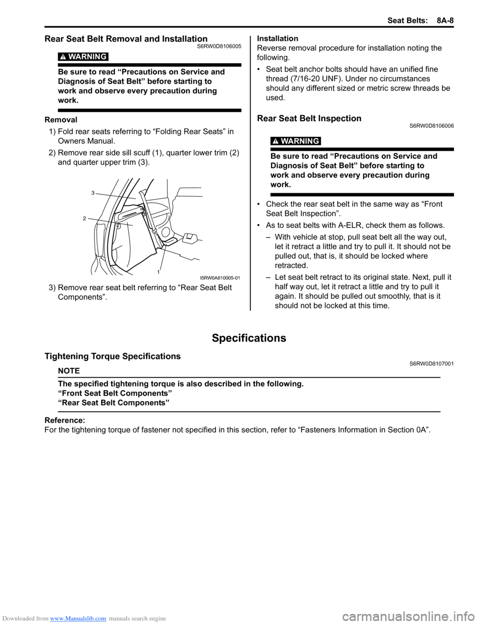
1) Fold rear seats referring to “Folding Rear Seats” in
Owners Manual.
2) Remove rear side sill scuff (1), quarter lower trim (2)
and quarter upper trim (3).
3) Remove rear seat belt referring to “Rear Seat Belt
Components”.Installation
Reverse removal procedure for installation noting the
following.
• Seat belt anchor bolts should have an unified fine
thread (7/16-20 UNF). Under no circumstances
should any different sized or metric screw threads be
used.Rear Seat Belt InspectionS6RW0D8106006
WARNING!
Be sure to read “Precautions on Service and
Diagnosis of Seat Belt” before starting to
work and observe every precaution during
work.
• Check the rear seat belt in the same way as “Front
Seat Belt Inspection”.
• As to seat belts with A-ELR, check them as follows.
– With vehicle at stop, pull seat belt all the way out,
let it retract a little and try to pull it. It should not be
pulled out, that is, it should be locked where
retracted.
– Let seat belt retract to its original state. Next, pull it
half way out, let it retract a little and try to pull it
again. It should be pulled out smoothly, that is it
should not be locked at this time.
Specifications
Tightening Torque SpecificationsS6RW0D8107001
NOTE
The specified tightening torque is also described in the following.
“Front Seat Belt Components”
“Rear Seat Belt Components”
Reference:
For the tightening torque of fastener not specified in this section, refer to “Fasteners Information in Section 0A”.
1 23I5RW0A810005-01
Page 1153 of 1556

Downloaded from www.Manualslib.com manuals search engine Air Bag System: 8B-114
21) Wash your hands with mild soap and water
afterward.
NOTE
Remaining steps are to be followed in the
unlikely event that air bag (inflator) module
did not deploy or seat belt pretensioner did
not activate.
22) Ensure that deployment harness has been
disconnected from 12 volts vehicle battery and that
its two banana plugs have been shorted together by
fully seating one banana plug into the other.
23) Disconnect deployment harness and adapter cable
from air bag (inflator) module or seat belt
pretensioner.
24) Temporarily store undeployed air bag (inflator)
module referring to “Precautions on Service and
Diagnosis of Air Bag System” for details.
25) Contact your local distributor for further assistance.
Deployment / Activation Inside of Vehicle
When the vehicle will be destroyed, or salvaged for
component parts, deploy the air bag modules and/or
activate seat belt pretensioners installed on vehicle.
NOTE
If equipped with the seat belt pretensioners,
activate both side of seat belt pretensioners
at the same time when using special tool (C).
1) Turn ignition switch to LOCK position, remove key
and put on safety glasses.
2) Remove all loose objects from front seats and
instrument panel.
3) Disconnect air bag (inflator) module or seat belt
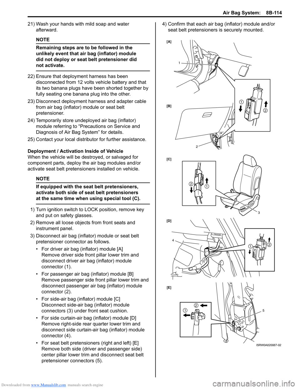
pretensioner connector as follows.
• For driver air bag (inflator) module [A]
Remove driver side front pillar lower trim and
disconnect driver air bag (inflator) module
connector (1).
• For passenger air bag (inflator) module [B]
Remove passenger side front pillar lower trim and
disconnect passenger air bag (inflator) module
connector (2).
• For side-air bag (inflator) module [C]
Disconnect side-air bag (inflator) module
connectors (3) under front seat cushion.
• For side curtain-air bag (inflator) module [D]
Remove right-side rear quarter lower trim and
disconnect side curtain-air bag (inflator) module
connector (4).
• For seat belt pretensioners (right and left) [E]
Remove both side (driver and passenger side)
center pillar lower trim and disconnect seat belt
pretensioner connectors (5).4) Confirm that each air bag (inflator) module and/or
seat belt pretensioners is securely mounted.
1
3
4
2
1
21
2
21
2
15 [A]
[B]
[C]
[D]
[E]
I5RW0A820087-02
Page 1430 of 1556

Downloaded from www.Manualslib.com manuals search engine 9G-3 Seats:
Front Seat Removal and InstallationS6RW0D9706002
Removal
1) Disable air bag system referring to “Disabling Air
Bag System in Section 8B”.
2) Disconnect seat harness coupler and side air bag
coupler, if equipped.
3) Remove 4 mounting bolts to remove seat assembly.
4) Disassemble and repair seat as necessary.
Installation
Reverse removal procedure to install front seat.
• Torque to specifications as shown in “Front Seat
Components”.
• Enable air bag system referring to “Enabling Air Bag
System in Section 8B”.
Front Seat Heater Switch (Driver and Passenger
Side) Inspection (If Equipped)
S6RW0D9706005
1) Confirm that ignition switch is OFF position.
2) Remove console box.
3) Disconnect seat heater switch coupler and remove
seat heater switch.
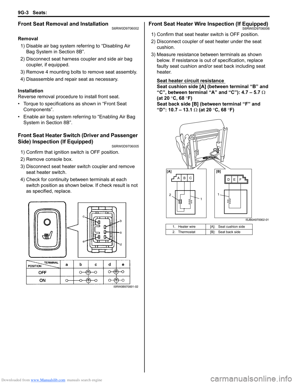
4) Check for continuity between terminals at each
switch position as shown below. If check result is not
as specified, replace.
Front Seat Heater Wire Inspection (If Equipped)S6RW0D9706006
1) Confirm that seat heater switch is OFF position.
2) Disconnect coupler of seat heater under the seat
cushion.
3) Measure resistance between terminals as shown
below. If resistance is out of specification, replace
faulty seat cushion and/or seat back including seat
heater.
Seat heater circuit resistance
Seat cushion side [A] (between terminal “B” and
“C”, between terminal “A” and “C”): 4.7 – 5.7 Ω
(at 20 °C, 68 °F)
Seat back side [B] (between terminal “F” and
“D”: 10.7 – 13.1 Ω (at 20 °C, 68 °F)
I5RW0B970001-02
1. Heater wire [A]: Seat cushion side
2. Thermostat [B]: Seat back side
ABCDE F [A] [B]
11
2
I5JB0A970002-01
Page 1431 of 1556

Downloaded from www.Manualslib.com manuals search engine Seats: 9G-4
Rear Seat ComponentsS6RW0D9706003
Rear Seat Removal and InstallationS6RW0D9706004
Removal
1) Fold rear seat back forward.
2) Remove seat mounting bolts and nuts to remove seat assembly.
3) Disassemble and repair seat as necessary.
Installation
Reverse removal procedure to install rear seat.
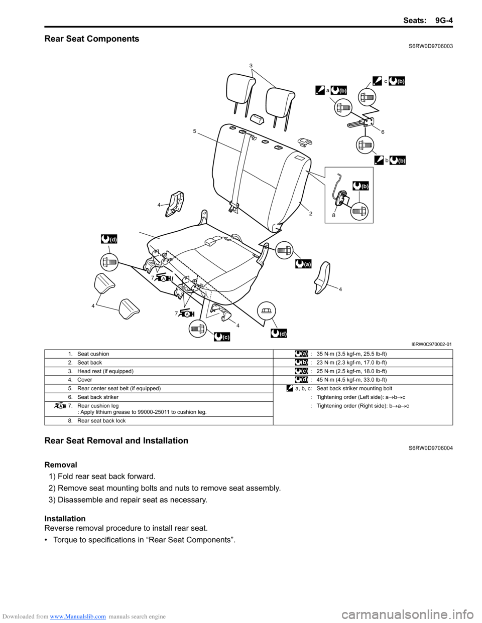
• Torque to specifications in “Rear Seat Components”.
3
5
4
4
4
7
4
2
6
b
c
a
(d)
(a)
(d)
(b)
(b)
(b)
(c)
A
7A
(b)
8
I6RW0C970002-01
1. Seat cushion:35 N⋅m (3.5 kgf-m, 25.5 lb-ft)
2. Seat back:23 N⋅m (2.3 kgf-m, 17.0 lb-ft)
3. Head rest (if equipped):25 N⋅m (2.5 kgf-m, 18.0 lb-ft)
4. Cover:45 N⋅m (4.5 kgf-m, 33.0 lb-ft)
5. Rear center seat belt (if equipped) a, b, c: Seat back striker mounting bolt
6. Seat back striker: Tightening order (Left side): a→b→c
7. Rear cushion leg
: Apply lithium grease to 99000-25011 to cushion leg.: Tightening order (Right side): b→a→c
8. Rear seat back lock