2006 SUZUKI SX4 open hood
[x] Cancel search: open hoodPage 41 of 1556

Downloaded from www.Manualslib.com manuals search engine Maintenance and Lubrication: 0B-10
Propeller Shaft (4WD) InspectionS6RW0D0206026
1) Check propeller shaft connecting bolts for
looseness. If looseness is found, tighten to specified
torque.
2) Check propeller shaft joints for wear, play and
damage. If any defect is found, replace.
3) Check propeller shaft center support for biting of
foreign matter, crank, abnormal noise and damage.
If any defect is found, replace.
Manual Transaxle Oil InspectionS6RW0D0206027
Check transaxle oil for leakage, contamination and level
referring to “Manual Transaxle Oil Level Check in
Section 5B”.
Manual Transaxle Oil ReplacementS6RW0D0206028
Change transaxle oil with new specified oil referring to
“Manual Transaxle Oil Change in Section 5B”.
Automatic Transaxle Fluid Level InspectionS6RW0D0206037
Check fluid for leakage, contamination and level
referring to“A/T Fluid Level Check in Section 5A”.
Automatic Transaxle Fluid ReplacementS6RW0D0206038
Change fluid referring to “A/T Fluid Change in Section
5A”.
Automatic Transaxle Fluid Cooler Hose
Inspection
S6RW0D0206039
Check automatic transaxle fluid cooler hose for fluid
leakage, cracks, damage and deterioration. Replace
hose and/or clamp if any faulty condition is found.
Transfer Oil Inspection (4WD)S6RW0D0206040
Check transfer oil for leakage, contamination and level
referring to “Transfer Oil Level Check in Section 3C”.
Transfer Oil Replacement (4WD)S6RW0D0206030
Change transfer oil with new specified oil referring to
“Transfer Oil Change in Section 3C”.
Rear Deferential Oil Inspection (4WD)S6RW0D0206031
Check differential oil for leakage, contamination and
level referring to “Rear Differential Oil Level Check in
Section 3B”.
Rear Deferential Oil Replacement (4WD)S6RW0D0206032
Change differential oil with new specified oil referring to
“Rear Differential Oil Change in Section 3B”.
All Latches, Hinges and Locks InspectionS6RW0D0206033
Doors
Check that each door of front, rear and back doors
opens and closes smoothly and locks securely when
closed.
If any malfunction is found, lubricate hinge and latch or
repair door lock system.
Engine Hood
Check that secondary latch operates properly (check
that secondary latch keeps hood from opening all the
way even when pulling hood release handle inside
vehicle.) Also check that hood opens and closes
smoothly and properly and hood locks securely when
closed.
If any malfunction is found, lubricate hinge and latch, or
repair hood lock system.I5RW0A020006-01
I5RW0C020001-01
I2RH01020033-01
Page 948 of 1556

Downloaded from www.Manualslib.com manuals search engine 7B-8 Air Conditioning System: Manual Type
Diagnostic Information and Procedures
A/C System Performance InspectionS6RW0D7214001
1) Confirm that vehicle and environmental conditions
are as follows.
• Vehicle is put indoors.
• Ambient temperature is within 25 – 35 °C (77 – 95
°F).
• Relative humidity is within 30 – 70%.
• There is no wind indoors.
• HVAC unit is normal.
• Blower motor is normal.
• There is no air leakage from air ducts.
• Condenser fins are clean.
• HVAC air filter is not clogged with dirt and dust (if
equipped).
• Battery voltage is about 12 V.
• Radiator cooling fan operates normally.
2) Make sure that high pressure valve (1) and low
pressure valve (2) of manifold gauge are firmly
closed.
3) Connect high pressure charging hose (3) to high
pressure service valve (5) on vehicle and low
pressure charging hose (4) to low pressure service
valve (6).
4) Bleed the air in charging hoses (3) and (4) by
loosening their nuts respectively utilizing the
refrigerant pressure. When a hissing sound is heard,
immediately tighten nut.
CAUTION!
Do not connect high and low pressure
charging hoses in reverse.
5) Warm up engine to the normal operating
temperature and keep it at the specified idle speed.
6) Turn A/C switch ON, set blower speed selector at
maximum speed position, temperature selector at
maximum cold position, air flow selector at face
position, and air intake selector at recirculation
position. (Confirm that A/C compressor, A/C
condenser cooling fan and radiator cooling fan are
working.)
7) Wait for ten minutes to stabilize the A/C operation.
8) Open all door windows, front doors and engine hood.
9) With about 20 mm (0.8 in.) of dry bulb thermometer
(1) put right in front of center ventilation louver and a
wet and dry bulb thermometer (2) near air inlet of
HVAC unit.
321
4
6
5
I7RW01721006-01
2
1
I5RW0A721008-01
Page 1165 of 1556
Downloaded from www.Manualslib.com manuals search engine Table of Contents 9-v
Power Door Lock System Symptom
Diagnosis (If Equipped)..................................... 9F-3
Power Door Lock System Operation
Inspection (If Equipped) .................................... 9F-3
Keyless Entry System Symptom Diagnosis (If
Equipped).......................................................... 9F-4
Keyless Entry System Operation Inspection
(If Equipped) ..................................................... 9F-5
Door Lock Function of Keyless Start System
Symptom Diagnosis (If Equipped) .................... 9F-5
Rear End Door Opener System Symptom
Diagnosis (If Equipped)..................................... 9F-5
Rear End Door Opener System Operation
Inspection (If Equipped) .................................... 9F-5
Repair Instructions .............................................. 9F-6
Front Door Lock Assembly Components ............ 9F-6
Front Door Lock Assembly Removal and
Installation ......................................................... 9F-6
Front Door Lock Assembly Inspection ................ 9F-8
Power Door Lock Switch Inspection (If
Equipped).......................................................... 9F-8
Door Key Cylinder Switch Inspection (If
Equipped).......................................................... 9F-8
Power Door Lock Actuator Inspection (If
Equipped).......................................................... 9F-9
Rear Door Lock Assembly Components ........... 9F-10
Rear Door Lock Assembly Removal and
Installation ....................................................... 9F-10
Rear Door Lock Assembly Inspection ............... 9F-10
Rear End Door Lock Assembly Components.... 9F-11
Rear End Door Lock Assembly Removal and
Installation ....................................................... 9F-12
Rear End Door Lock Assembly Inspection........ 9F-12
Rear End Door Opener Switch Inspection (If
Equipped)........................................................ 9F-12
Replacement of Transmitter Battery (Other
than Keyless Start Model) ............................... 9F-13
Programming Transmitter Code for Keyless
Entry System (Other than Keyless Start
Model) ............................................................. 9F-13
Keyless Entry Answer Back Function
Change-over Procedure (If Equipped) ............ 9F-14
Keyless Entry Receiver Removal and
Installation (If Equipped)................................. 9F-14
Keyless Entry Receiver and Its Circuit
Inspection (If Equipped) .................................. 9F-15
Specifications..................................................... 9F-16
Tightening Torque Specifications ...................... 9F-16
Special Tools and Equipment ........................... 9F-16
Recommended Service Material ....................... 9F-16
Seats ......................................................... 9G-1
Diagnostic Information and Procedures ............9G-1
Front Seat Heater Symptom Diagnosis (If
Equipped)..........................................................9G-1
Repair Instructions ..............................................9G-2
Front Seat Components ......................................9G-2
Front Seat Removal and Installation ...................9G-3Front Seat Heater Switch (Driver and
Passenger Side) Inspection (If Equipped)........ 9G-3
Front Seat Heater Wire Inspection (If
Equipped) ......................................................... 9G-3
Rear Seat Components...................................... 9G-4
Rear Seat Removal and Installation................... 9G-4
Specifications ...................................................... 9G-5
Tightening Torque Specifications ....................... 9G-5
Special Tools and Equipment ............................ 9G-5
Recommended Service Material ........................ 9G-5
Interior Trim ............................................. 9H-1
Repair Instructions ..............................................9H-1
Floor Carpet Removal and Installation ................9H-1
Head Lining Removal and Installation.................9H-2
Console Box Components ..................................9H-3
Specifications .......................................................9H-4
Tightening Torque Specifications ........................9H-4
Hood / Fenders / Doors ............................ 9J-1
Repair Instructions .............................................. 9J-1
Hood Removal and Installation ........................... 9J-1
Hood Inspection and Adjustment ........................ 9J-1
Front Fender Components .................................. 9J-2
Front Fender Removal and Installation ............... 9J-2
Front Door Assembly Components ..................... 9J-3
Front Door Assembly Removal and
Installation ......................................................... 9J-3
Rear Door Assembly Components...................... 9J-5
Rear Door Assembly Removal and
Installation ......................................................... 9J-5
Rear End Door Assembly Components .............. 9J-6
Rear End Door Assembly Removal and
Installation ......................................................... 9J-6
Specifications ....................................................... 9J-8
Tightening Torque Specifications ........................ 9J-8
Special Tools and Equipment ............................. 9J-8
Recommended Service Material ......................... 9J-8
Body Structure......................................... 9K-1
Repair Instructions ..............................................9K-1
Front Bumper and Rear Bumper Components .... 9K-1
Cowl Top and Front Lower Crossmember
Components ...................................................... 9K-2
Specifications .......................................................9K-3
Body Dimensions ................................................ 9K-3
Panel Clearance................................................ 9K-10
Tightening Torque Specifications ...................... 9K-10
Paint / Coatings ........................................9L-1
General Description ............................................. 9L-1
Anti-Corrosion Treatment Construction............... 9L-1
Plastic Parts Finishing ......................................... 9L-2
Component Location ........................................... 9L-3
Sealant Application Areas ................................... 9L-3
Under Coating Application Areas ...................... 9L-10
Anti-Corrosion Compound Application Area ..... 9L-12
Exterior Trim ............................................ 9M-1
Page 1404 of 1556
Downloaded from www.Manualslib.com manuals search engine 9E-19 Glass / Windows / Mirrors:
Rear End Door Window Defogger Relay
Inspection
S6RW0D9506018
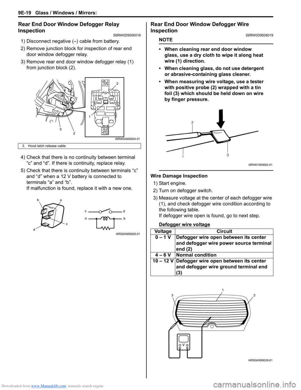
1) Disconnect negative (–) cable from battery.
2) Remove junction block for inspection of rear end
door window defogger relay.
3) Remove rear end door window defogger relay (1)
from junction block (2).
4) Check that there is no continuity between terminal
“c” and “d”. If there is continuity, replace relay.
5) Check that there is continuity between terminals “c”
and “d” when a 12 V battery is connected to
terminals “a” and “b”.
If malfunction is found, replace it with a new one.
Rear End Door Window Defogger Wire
Inspection
S6RW0D9506019
NOTE
• When cleaning rear end door window
glass, use a dry cloth to wipe it along heat
wire (1) direction.
• When cleaning glass, do not use detergent
or abrasive-containing glass cleaner.
• When measuring wire voltage, use a tester
with positive probe (2) wrapped with a tin
foil (3) which should be held down on wire
by finger pressure.
Wire Damage Inspection
1) Start engine.
2) Turn on defogger switch.
3) Measure voltage at the center of each defogger wire
(1), and check defogger wire condition according to
the following table.
If defogger wire open is found, go to next step.
Defogger wire voltage
3. Hood latch release cable
12
2
3
I5RW0A950034-01
ba
c
dc
ad
bI4RS0A950028-01Voltage Circuit
0 – 1 V Defogger wire open between its center
and defogger wire power source terminal
end (2)
4 – 6 V Normal condition
10 – 12 V Defogger wire open between its center
and defogger wire ground terminal end
(3)
I2RH01950002-01
2
1
3
I4RS0A950029-01
Page 1437 of 1556
Downloaded from www.Manualslib.com manuals search engine Hood / Fenders / Doors: 9J-1
Body, Cab and Accessories
Hood / Fenders / Doors
Repair Instructions
Hood Removal and InstallationS6RW0D9A06001
Removal
CAUTION!
Place cloth to prevent body from any
damage.
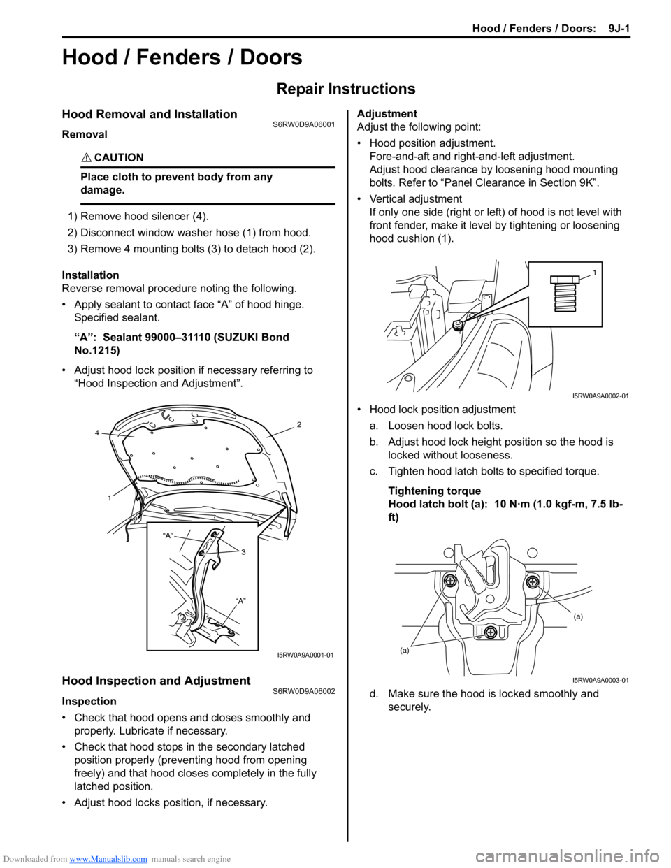
1) Remove hood silencer (4).
2) Disconnect window washer hose (1) from hood.
3) Remove 4 mounting bolts (3) to detach hood (2).
Installation
Reverse removal procedure noting the following.
• Apply sealant to contact face “A” of hood hinge.
Specified sealant.
“A”: Sealant 99000–31110 (SUZUKI Bond
No.1215)
• Adjust hood lock position if necessary referring to
“Hood Inspection and Adjustment”.
Hood Inspection and AdjustmentS6RW0D9A06002
Inspection
• Check that hood opens and closes smoothly and
properly. Lubricate if necessary.
• Check that hood stops in the secondary latched
position properly (preventing hood from opening
freely) and that hood closes completely in the fully
latched position.
• Adjust hood locks position, if necessary.Adjustment
Adjust the following point:
• Hood position adjustment.
Fore-and-aft and right-and-left adjustment.
Adjust hood clearance by loosening hood mounting
bolts. Refer to “Panel Clearance in Section 9K”.
• Vertical adjustment
If only one side (right or left) of hood is not level with
front fender, make it level by tightening or loosening
hood cushion (1).
• Hood lock position adjustment
a. Loosen hood lock bolts.
b. Adjust hood lock height position so the hood is
locked without looseness.
c. Tighten hood latch bolts to specified torque.
Tightening torque
Hood latch bolt (a): 10 N·m (1.0 kgf-m, 7.5 lb-
ft)
d. Make sure the hood is locked smoothly and
securely.
2
4
1
3 “A”
“A”
I5RW0A9A0001-01
1
I5RW0A9A0002-01
(a)(a)
I5RW0A9A0003-01
Page 1439 of 1556
Downloaded from www.Manualslib.com manuals search engine Hood / Fenders / Doors: 9J-3
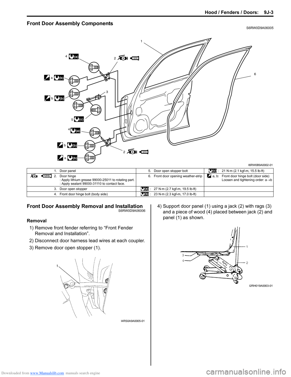
Front Door Assembly ComponentsS6RW0D9A06005
Front Door Assembly Removal and InstallationS6RW0D9A06006
Removal
1) Remove front fender referring to “Front Fender
Removal and Installation”.
2) Disconnect door harness lead wires at each coupler.
3) Remove door open stopper (1).4) Support door panel (1) using a jack (2) with rags (3)
and a piece of wood (4) placed between jack (2) and
panel (1) as shown.
2
24
45
3
1
6
(a)
(a)
(c) a
(b)
b(b)
a(b) b
(b)
I6RW0B9A0002-01
1. Door panel 5. Door open stopper bolt : 21 N⋅m (2.1 kgf-m, 15.5 lb-ft)
2. Door hinge
: Apply lithium grease 99000-25011 to rotating part.
: Apply sealant 99000-31110 to contact face.6. Front door opening weather-strip a, b: Front door hinge bolt (door side)
Loosen and tightening order: a→b
3. Door open stopper : 27 N⋅m (2.7 kgf-m, 19.5 lb-ft)
4. Front door hinge bolt (body side) : 23 N⋅m (2.3 kgf-m, 17.0 lb-ft)
I4RS0A9A0005-01
I2RH019A0003-01
Page 1440 of 1556
Downloaded from www.Manualslib.com manuals search engine 9J-4 Hood / Fenders / Doors:
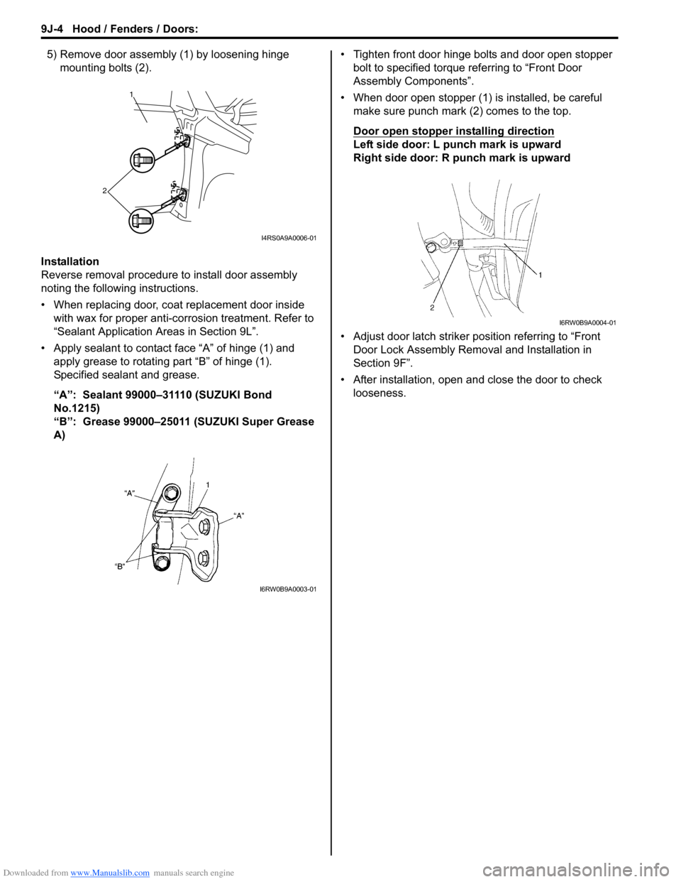
5) Remove door assembly (1) by loosening hinge
mounting bolts (2).
Installation
Reverse removal procedure to install door assembly
noting the following instructions.
• When replacing door, coat replacement door inside
with wax for proper anti-corrosion treatment. Refer to
“Sealant Application Areas in Section 9L”.
• Apply sealant to contact face “A” of hinge (1) and
apply grease to rotating part “B” of hinge (1).
Specified sealant and grease.
“A”: Sealant 99000–31110 (SUZUKI Bond
No.1215)
“B”: Grease 99000–25011 (SUZUKI Super Grease
A) • Tighten front door hinge bolts and door open stopper
bolt to specified torque referring to “Front Door
Assembly Components”.
• When door open stopper (1) is installed, be careful
make sure punch mark (2) comes to the top.
Door open stopper installing direction
Left side door: L punch mark is upward
Right side door: R punch mark is upward
• Adjust door latch striker position referring to “Front
Door Lock Assembly Removal and Installation in
Section 9F”.
• After installation, open and close the door to check
looseness.
1
2
I4RS0A9A0006-01
I6RW0B9A0003-01
I6RW0B9A0004-01
Page 1441 of 1556
Downloaded from www.Manualslib.com manuals search engine Hood / Fenders / Doors: 9J-5
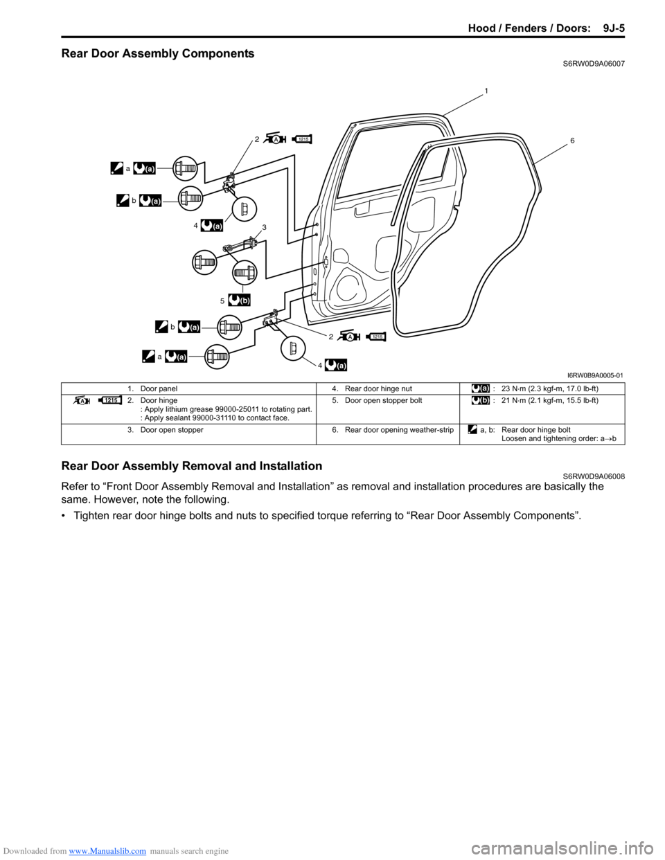
Rear Door Assembly ComponentsS6RW0D9A06007
Rear Door Assembly Removal and InstallationS6RW0D9A06008
Refer to “Front Door Assembly Removal and Installation” as removal and installation procedures are basically the
same. However, note the following.
• Tighten rear door hinge bolts and nuts to specified torque referring to “Rear Door Assembly Components”.
2
2
4
5
4 3
1
6
(a)
(a)
(b)
a(a) b
(a)
a(a)
b
(a)
I6RW0B9A0005-01
1. Door panel 4. Rear door hinge nut : 23 N⋅m (2.3 kgf-m, 17.0 lb-ft)
2. Door hinge
: Apply lithium grease 99000-25011 to rotating part.
: Apply sealant 99000-31110 to contact face.5. Door open stopper bolt : 21 N⋅m (2.1 kgf-m, 15.5 lb-ft)
3. Door open stopper 6. Rear door opening weather-strip a, b: Rear door hinge bolt
Loosen and tightening order: a→b