2006 SUZUKI SX4 Audio
[x] Cancel search: AudioPage 11 of 1556

Downloaded from www.Manualslib.com manuals search engine Precautions: 00-4
WARNING!
• Whenever raising a vehicle for service, be
sure to follow the instructions under
“Vehicle Lifting Points in Section 0A”.
• When it is necessary to do service work
with the engine running, make sure that
the parking brake is set fully and the
transmission is in Neutral (for manual
transmission vehicles) or Park (for
automatic transmission vehicles), Keep
hands, hair, clothing, tools, etc. away from
the fan and belts when the engine is
running.
• When it is necessary to run the engine
indoors, make sure that the exhaust gas is
forced outdoors.
• Do not perform service work in areas
where combustible materials can come in
contact with a hot exhaust system. When
working with toxic or flammable materials
(such as gasoline and refrigerant), make
sure that the area you work in is well-
ventilated.
• To avoid getting burned, keep away from
hot metal parts such as the radiator,
exhaust manifold, tail pipe, muffler, etc.
• New and used engine oil can be
hazardous. Children and pets may be
harmed by swallowing new or used oil.
Keep new and used oil and used engine oil
filters away from children and pets.
Continuous contact with used engine oil
has been found to cause [skin] cancer in
laboratory animals. Brief contact with used
oil may irritate skin. To minimize your
exposure to used engine oil, wear a long-
sleeve shirt and moisture-proof gloves
(such as dish washing gloves) when
changing engine oil. If engine oil contacts
your skin, wash thoroughly with soap and
water. Launder any clothing or rags if wet
with oil, recycle or properly dispose of
used oil and filters.
• Be sure to observe following instructions
when handling service materials such as
fuel, oil, fluid, coolant, grease, sealant,
thread lock cement, etc. Otherwise, your
health may be ruined.
– Whenever handling any of these service
materials, wear safety glasses to protect
your eyes. If it gets into your eye, it may
cause inflammation.
– Whenever handling any of these service
materials, wear moisture-proof gloves to
protect your skin. If it adheres to your
skin, it may cause inflammation.– Do not swallow any of these service
materials. It would cause diarrhea or
nausea.
– Keep all these materials out of children’s
reach.
• Make sure the bonnet is fully closed and
latched before driving. If it is not, it can fly
up unexpectedly during driving,
obstructing your view and resulting in an
accident.
• Before starting any service work, cover fenders, seats
and any other parts that are likely to get scratched or
stained during servicing. Also, be aware that what you
wear (e.g., buttons) may cause damage to the
vehicle’s finish.
• When performing service to electrical parts that does
not require use of battery power, disconnect the
negative cable of the battery.
• When disconnecting the negative cable from the
battery, be careful to the following.
– Check and record DTCs in ECM, HVAC control
module and/or PS control module if necessary
before disconnecting.
– Record displayed contents of the clock and/or
audio system, etc. before disconnecting and reset it
as before after connecting.
– For vehicle equipped with electric throttle body
system, perform electric throttle body system
calibration referring to “Electric Throttle Body
System Calibration in Section 1C” after
reconnecting the negative cable to the battery.
I2RH01010025-01
I2RH01010026-01
Page 873 of 1556

Downloaded from www.Manualslib.com manuals search engine Steering Wheel and Column: 6B-4
Steering Wheel Removal and InstallationS6RW0D6206002
CAUTION!
Do not turn the contact coil more than
allowable number of turns (about two and a
half turns from the center position clockwise
or counterclockwise respectively) with
steering wheel removed, or coil will break.
Removal
CAUTION!
Do not hammer the end of the shaft.
Hammering it will loosen the plastic shear
pins which maintain the column length and
impair the collapsible design of the column.
1) Disconnect negative (–) cable at battery.
2) Disable air bag system referring to “Disabling Air
Bag System in Section 8B”.
3) Remove driver air bag (inflator) module from
steering wheel. Refer to “Driver Air Bag (Inflator)
Module Removal and Installation in Section 8B”.
4) Disconnect horn connector and audio control switch
connector, if equipped.
5) Remove steering shaft nut and then make alignment
marks (1) on steering wheel and shaft for a guide
during reinstallation.6) Remove steering wheel using special tool.
Special tool
(A): 09944–36011
InstallationCAUTION!
Following 2 Steps (Step 1) and 2)) are
prerequisite for installation of steering wheel.
If steering wheel has been installed without
these 2 Steps, contact coil will break when
steering wheel is turned.
1) Check that vehicle’s front tires are at straight-ahead
position and contact coil is centered. If contact coil is
turned after removing steering wheel, center contact
coil referring to “Centering Contact Coil Cable
Assembly”.
2) Install steering wheel to steering shaft with 2 grooves
(1) on contact coil fitted in 2 lugs (2) in the back of
steering wheel and also aligning marks (3) on
steering wheel and steering shaft.
3) Tighten steering shaft nut (4) to specified torque.
Tightening torque
Steering shaft nut (a): 33 N·m (3.3 kgf-m, 24.0 lb-
ft)
I4RS0A620005-01
(A)
I4RS0A620006-01
I4RS0A620007-01
Page 874 of 1556

Downloaded from www.Manualslib.com manuals search engine 6B-5 Steering Wheel and Column:
4) Connect horn connector and audio control switch
connector, if necessary.
5) Install driver air bag (inflator) module to steering
wheel. Refer to “Driver Air Bag (Inflator) Module
Removal and Installation in Section 8B”.
6) Connect negative (–) cable to battery.
7) Enable air bag system referring to “Enabling Air Bag
System in Section 8B”.
Contact Coil Cable Assembly Removal and
Installation
S6RW0D6206003
CAUTION!
Do not turn contact coil more than allowable
number of turns (about two and a half turns
from the center position clockwise or
counterclockwise respectively), or coil will
break.
Removal
1) Disconnect negative (–) cable at battery.
2) Disable air bag system referring to “Disabling Air
Bag System in Section 8B”.
3) Remove steering wheel from steering column
referring to “Steering Wheel Removal and
Installation”.
4) Remove steering column hole cover.
5) Remove steering column lower cover (2) and upper
cover (1).6) Remove contact coil cable assembly (1) from
steering column.
Installation
1) Check to make sure that vehicle’s front tires are set
at straight-ahead position and then ignition switch is
at LOCK position.
2) Install contact coil cable assembly to steering
column securely.
NOTE
New contact coil cable assembly is supplied
with contact coil set and held at its center
position with a lock pin (1). Remove this lock
pin after installing contact coil cable
assembly to steering column.
2
1
I6RW0B620005-01
1I6RW0B620009-02
I4RS0A620010-01
Page 935 of 1556

Downloaded from www.Manualslib.com manuals search engine Heater and Ventilation: 7A-7
HVAC Control Unit Removal and InstallationS6RW0D7106009
Removal
1) Disconnect negative (–) cable at battery.
2) Remove steering column hole cover from instrument
panel.
3) Remove audio unit from instrument panel referring to
“Audio Unit Removal and Installation (If Equipped) in
Section 9C”.
4) Remove driver side foot duct (1) from HVAC unit by
removing screw (2).
5) Disconnect temperature control cable (1) and air
flow control cable (2) from HVAC unit (3).
LH steering vehicleRH steering vehicle
6) Remove center garnish from instrument panel.
7) Remove HVAC control unit from instrument panel.
8) Disconnect connectors from HVAC control unit.
Installation
Reverse removal procedure noting the following
instructions.
• Connect temperature control cable and air flow control
cable of HVAC control unit to links of HVAC unit.
a. For LH steering vehicle, set airflow selector (1) to
“DEF” position and temperature selector (2) to
“MAX HOT” position.
For RH steering vehicle, set airflow selector (1) to
“VENT” position and temperature selector (2) to
“MAX COOL” position.
1
2
I7RW01710010-01
I7RW01710012-02
F: Vehicle forward
I6RW0C710005-01
12I4RS0B710013-01
12I4RS0A710016-01
Page 939 of 1556

Downloaded from www.Manualslib.com manuals search engine Heater and Ventilation: 7A-11
Center Ventilation Louver Removal and
Installation
S6RW0D7106014
Removal
1) Disconnect negative (–) cable from battery.
2) Remove audio unit from instrument panel referring to
“Audio Unit Removal and Installation (If Equipped) in
Section 9C”.
3) Remove center ventilation louver (1) with garnish (2)
from instrument panel, and then disconnect
connector from hazard switch.
NOTE
Garnish is fitted to instrument panel with six
clips. When removing garnish from
instrument panel, be careful not to break
them.
4) Separate center ventilation louver and garnish.
Installation
Reverse removal procedure.
Side Ventilation Louver Removal and
Installation
S6RW0D7106015
Removal
1) Remove instrument panel from vehicle body
referring to “Instrument Panel Removal and
Installation in Section 9C”
2) Remove steering support member (1), defroster
nozzle (2) and ventilator duct (3) from instrument
panel.3) Remove side ventilation louver (1) from instrument
panel while pressing clips (2).
Installation
Reverse removal procedure noting the following
instruction.
• Side ventilation louver is fitted to instrument panel
with four clips (1). When installing side ventilation
louver to instrument panel, position the smallest clip to
the top.
1
2
I5RW0A710008-01
3
12
I5RW0A710009-01
1
2
2
I5RW0A710010-01
1
1
I5RW0A710011-01
Page 1025 of 1556

Downloaded from www.Manualslib.com manuals search engine Air Conditioning System: Automatic Type 7B-85
Blower Motor Controller InspectionS6RW0D7226012
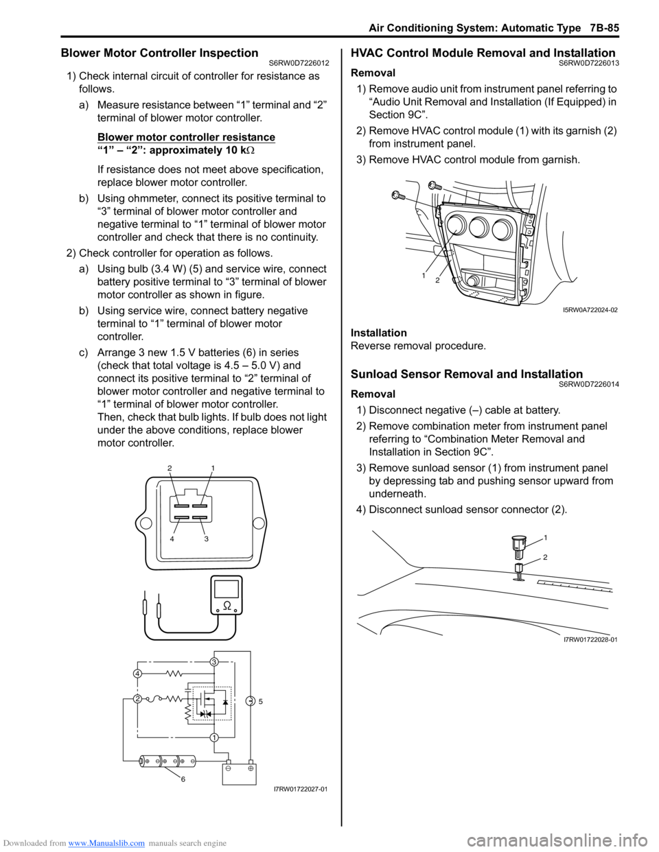
1) Check internal circuit of controller for resistance as
follows.
a) Measure resistance between “1” terminal and “2”
terminal of blower motor controller.
Blower motor controller resistance
“1” – “2”: approximately 10 kΩ
If resistance does not meet above specification,
replace blower motor controller.
b) Using ohmmeter, connect its positive terminal to
“3” terminal of blower motor controller and
negative terminal to “1” terminal of blower motor
controller and check that there is no continuity.
2) Check controller for operation as follows.
a) Using bulb (3.4 W) (5) and service wire, connect
battery positive terminal to “3” terminal of blower
motor controller as shown in figure.
b) Using service wire, connect battery negative
terminal to “1” terminal of blower motor
controller.
c) Arrange 3 new 1.5 V batteries (6) in series
(check that total voltage is 4.5 – 5.0 V) and
connect its positive terminal to “2” terminal of
blower motor controller and negative terminal to
“1” terminal of blower motor controller.
Then, check that bulb lights. If bulb does not light
under the above conditions, replace blower
motor controller.
HVAC Control Module Removal and InstallationS6RW0D7226013
Removal
1) Remove audio unit from instrument panel referring to
“Audio Unit Removal and Installation (If Equipped) in
Section 9C”.
2) Remove HVAC control module (1) with its garnish (2)
from instrument panel.
3) Remove HVAC control module from garnish.
Installation
Reverse removal procedure.
Sunload Sensor Removal and InstallationS6RW0D7226014
Removal
1) Disconnect negative (–) cable at battery.
2) Remove combination meter from instrument panel
referring to “Combination Meter Removal and
Installation in Section 9C”.
3) Remove sunload sensor (1) from instrument panel
by depressing tab and pushing sensor upward from
underneath.
4) Disconnect sunload sensor connector (2).
21
43
3
1 2 4
5
6I7RW01722027-01
12
I5RW0A722024-02
1
2
I7RW01722028-01
Page 1026 of 1556

Downloaded from www.Manualslib.com manuals search engine 7B-86 Air Conditioning System: Automatic Type
Installation
Reverse removal procedure noting the following
instructions.
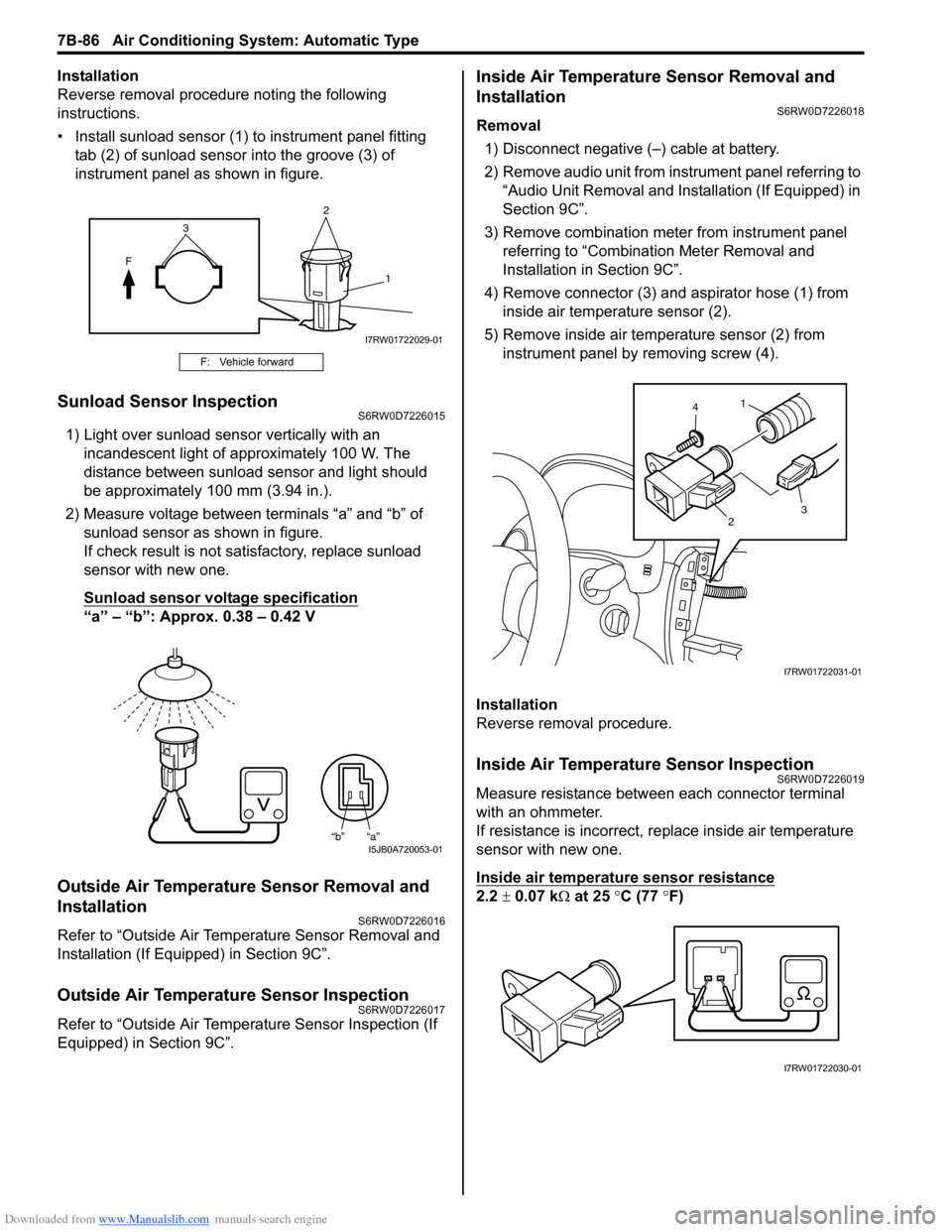
• Install sunload sensor (1) to instrument panel fitting
tab (2) of sunload sensor into the groove (3) of
instrument panel as shown in figure.
Sunload Sensor InspectionS6RW0D7226015
1) Light over sunload sensor vertically with an
incandescent light of approximately 100 W. The
distance between sunload sensor and light should
be approximately 100 mm (3.94 in.).
2) Measure voltage between terminals “a” and “b” of
sunload sensor as shown in figure.
If check result is not satisfactory, replace sunload
sensor with new one.
Sunload sensor voltage specification
“a” – “b”: Approx. 0.38 – 0.42 V
Outside Air Temperature Sensor Removal and
Installation
S6RW0D7226016
Refer to “Outside Air Temperature Sensor Removal and
Installation (If Equipped) in Section 9C”.
Outside Air Temperature Sensor InspectionS6RW0D7226017
Refer to “Outside Air Temperature Sensor Inspection (If
Equipped) in Section 9C”.
Inside Air Temperature Sensor Removal and
Installation
S6RW0D7226018
Removal
1) Disconnect negative (–) cable at battery.
2) Remove audio unit from instrument panel referring to
“Audio Unit Removal and Installation (If Equipped) in
Section 9C”.
3) Remove combination meter from instrument panel
referring to “Combination Meter Removal and
Installation in Section 9C”.
4) Remove connector (3) and aspirator hose (1) from
inside air temperature sensor (2).
5) Remove inside air temperature sensor (2) from
instrument panel by removing screw (4).
Installation
Reverse removal procedure.
Inside Air Temperature Sensor InspectionS6RW0D7226019
Measure resistance between each connector terminal
with an ohmmeter.
If resistance is incorrect, replace inside air temperature
sensor with new one.
Inside air temperature sensor resistance
2.2 ± 0.07 kΩ at 25 °C (77 °F)
F: Vehicle forward
2
F
1
3
I7RW01722029-01
“b” “a”I5JB0A720053-01
1
23 4
I7RW01722031-01
I7RW01722030-01
Page 1127 of 1556

Downloaded from www.Manualslib.com manuals search engine Air Bag System: 8B-88
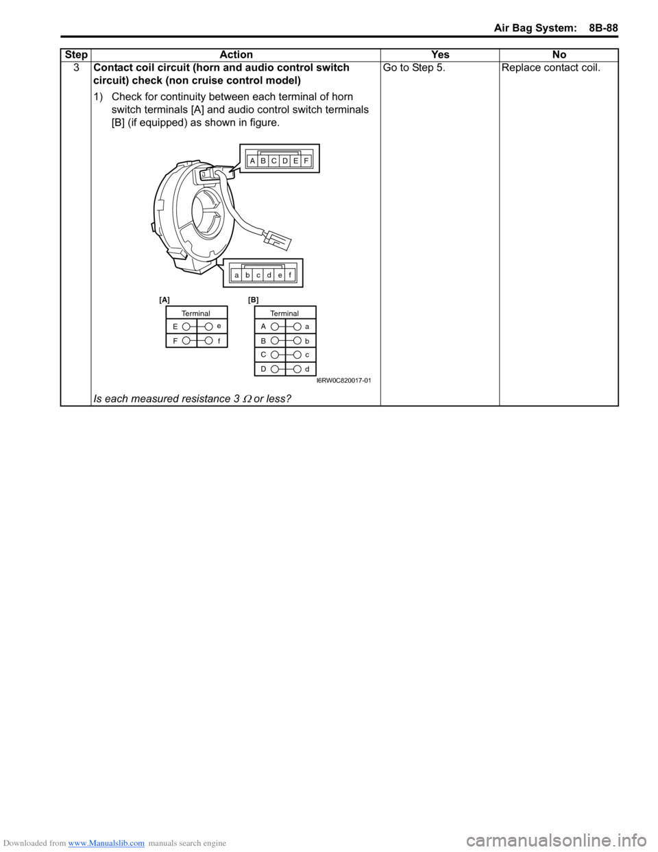
3Contact coil circuit (horn and audio control switch
circuit) check (non cruise control model)
1) Check for continuity between each terminal of horn
switch terminals [A] and audio control switch terminals
[B] (if equipped) as shown in figure.
Is each measured resistance 3
Ω or less?Go to Step 5. Replace contact coil. Step Action Yes No
ABCDEF
abcdef
A
Ba
b
TerminalTerminal
C
Dc
d E
Fe
f
[A] [B]
I6RW0C820017-01