2006 SUZUKI SX4 Motor
[x] Cancel search: MotorPage 1381 of 1556
Downloaded from www.Manualslib.com manuals search engine Wipers / Washers: 9D-7
Rear Wiper Motor InspectionS6RW0D9406007
NOTE
Make sure that battery voltage is 12 V or
more.
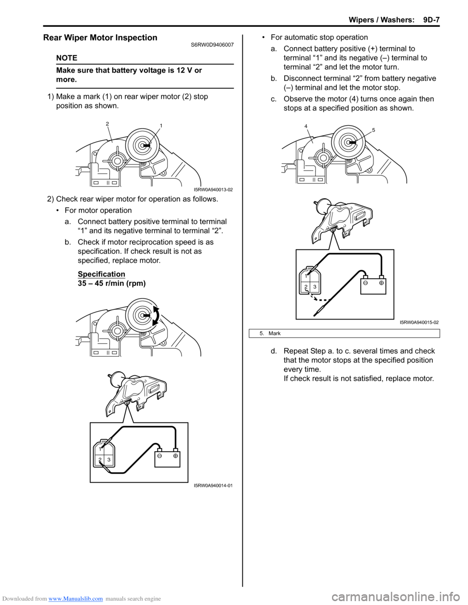
1) Make a mark (1) on rear wiper motor (2) stop
position as shown.
2) Check rear wiper motor for operation as follows.
• For motor operation
a. Connect battery positive terminal to terminal
“1” and its negative terminal to terminal “2”.
b. Check if motor reciprocation speed is as
specification. If check result is not as
specified, replace motor.
Specification
35 – 45 r/min (rpm)• For automatic stop operation
a. Connect battery positive (+) terminal to
terminal “1” and its negative (–) terminal to
terminal “2” and let the motor turn.
b. Disconnect terminal “2” from battery negative
(–) terminal and let the motor stop.
c. Observe the motor (4) turns once again then
stops at a specified position as shown.
d. Repeat Step a. to c. several times and check
that the motor stops at the specified position
every time.
If check result is not satisfied, replace motor.
2
1
I5RW0A940013-02
1
23
I5RW0A940014-01
5. Mark
1
23
45
I5RW0A940015-02
Page 1385 of 1556
Downloaded from www.Manualslib.com manuals search engine Wipers / Washers: 9D-11
Specifications
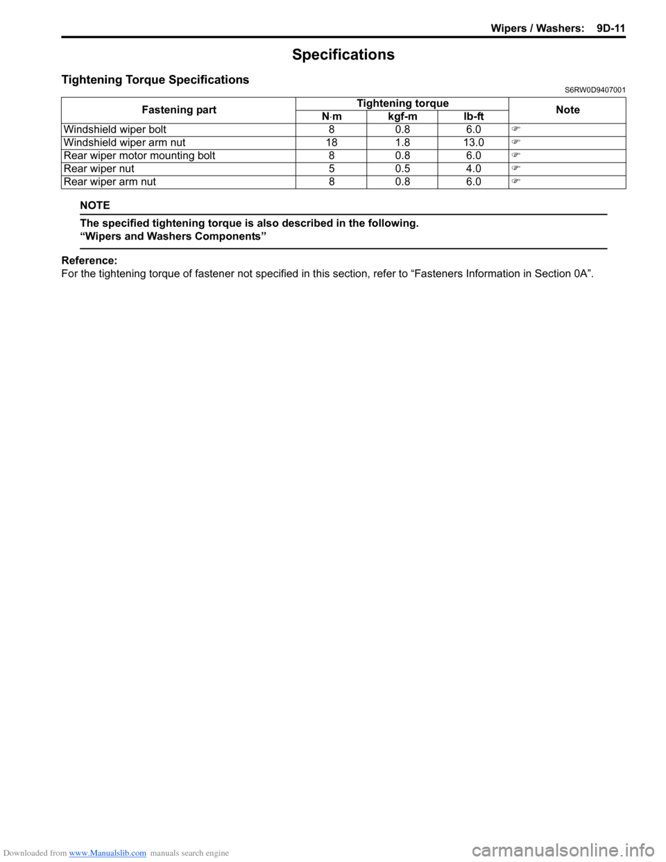
Tightening Torque SpecificationsS6RW0D9407001
NOTE
The specified tightening torque is also described in the following.
“Wipers and Washers Components”
Reference:
For the tightening torque of fastener not specified in this section, refer to “Fasteners Information in Section 0A”. Fastening partTightening torque
Note
N⋅mkgf-mlb-ft
Windshield wiper bolt 8 0.8 6.0�)
Windshield wiper arm nut 18 1.8 13.0�)
Rear wiper motor mounting bolt 8 0.8 6.0�)
Rear wiper nut 5 0.5 4.0�)
Rear wiper arm nut 8 0.8 6.0�)
Page 1386 of 1556
Downloaded from www.Manualslib.com manuals search engine 9E-1 Glass / Windows / Mirrors:
Body, Cab and Accessories
Glass / Windows / Mirrors
Precautions
Precautions for Power Window Service (Pinching Prevention Function Model)S6RW0D9500001
WARNING!
When checking the pinching prevention function, never attempt intentionally to have your hand, arm
or any other part of the body pinched. Also, use full care not to have your body caught.
• Do not drop the power window regulator (motor) or expose it to a strong impact in any other way.
• Do not operate the motor unless the power window regulator (motor) is installed and ready to operate door glass.
• If any peripheral part has bean damaged, replace regulator (motor) as well depending on the damage condition.
• After replacing or disconnecting the driver side power window regulator (motor), power window main switch, battery
and/or fuse, make sure to execute the initial setting, (to have the door glass closed position learned) refer to “Power
Window Main Switch Initialization (Pinching Prevention Function Model)”.
General Description
Rear End Door Window Defogger System DescriptionS6RW0D9501001
The rear end door window defogger is controlled by BCM. For the BCM description refer to “BCM General Description
in Section 10B”.
Page 1387 of 1556
Downloaded from www.Manualslib.com manuals search engine Glass / Windows / Mirrors: 9E-2
Schematic and Routing Diagram
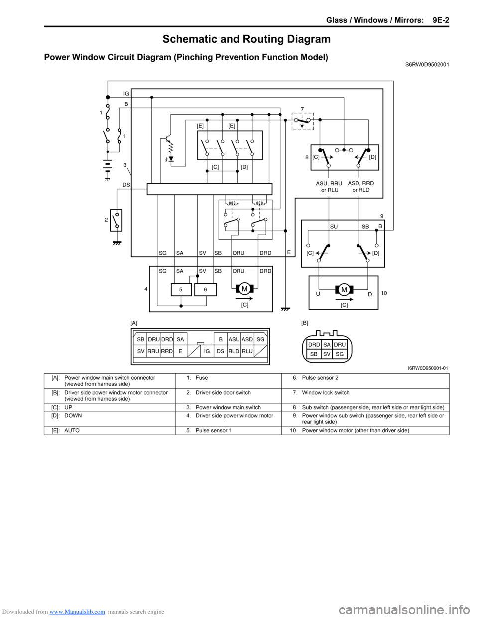
Power Window Circuit Diagram (Pinching Prevention Function Model)S6RW0D9502001
6 5
[C][D]
DSB IG
E
SG SV SBSA DRU DRD
SG SV SBSA DRU DRDASU, RRU
or RLUASD, RRD
or RLD
[C][C]
D U
[C][D]
SU SBB [C][D] [E] [E]
ESG
SV SB SADRU DRD B ASU ASD
RRU
RRDDS IG RLD RLUSG SV SBSA DRU DRD [A] [B] 1
1
3
2
47
8
9
10
I6RW0D950001-01
[A]: Power window main switch connector
(viewed from harness side)1. Fuse 6. Pulse sensor 2
[B]: Driver side power window motor connector
(viewed from harness side)2. Driver side door switch 7. Window lock switch
[C]: UP 3. Power window main switch 8. Sub switch (passenger side, rear left side or rear light side)
[D]: DOWN 4. Driver side power window motor 9. Power window sub switch (passenger side, rear left side or
rear light side)
[E]: AUTO 5. Pulse sensor 1 10. Power window motor (other than driver side)
Page 1388 of 1556
Downloaded from www.Manualslib.com manuals search engine 9E-3 Glass / Windows / Mirrors:
Diagnostic Information and Procedures
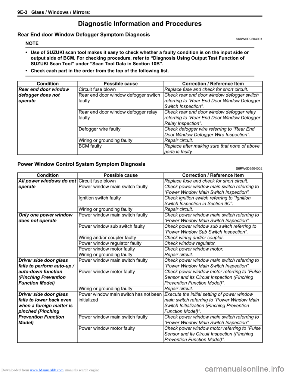
Rear End door Window Defogger Symptom DiagnosisS6RW0D9504001
NOTE
• Use of SUZUKI scan tool makes it easy to check whether a faulty condition is on the input side or
output side of BCM. For checking procedure, refer to “Diagnosis Using Output Test Function of
SUZUKI Scan Tool” under “Scan Tool Data in Section 10B”.
• Check each part in the order from the top of the following list.
Power Window Control System Symptom DiagnosisS6RW0D9504002
Condition Possible cause Correction / Reference Item
Rear end door window
defogger does not
operateCircuit fuse blownReplace fuse and check for short circuit.
Rear end door window defogger switch
faultyCheck rear end door window defogger switch
referring to “Rear End Door Window Defogger
Switch Inspection”.
Rear end door window defogger relay
faultyCheck rear end door window defogger relay
referring to “Rear End Door Window Defogger
Relay Inspection”.
Defogger wire faultyCheck defogger wire referring to “Rear End
Door Window Defogger Wire Inspection”.
Wiring or grounding faultyRepair circuit.
BCM faultyReplace after making sure that none of above
parts is faulty.
Condition Possible cause Correction / Reference Item
All power windows do not
operateCircuit fuse blownReplace fuse and check for short circuit.
Power window main switch faultyCheck power window main switch referring to
“Power Window Main Switch Inspection”.
Ignition switch faultyCheck ignition switch referring to “Ignition
Switch Inspection in Section 9C”.
Wiring or grounding faultyRepair circuit.
Only one power window
does not operatePower window main switch faultyCheck power window main switch referring to
“Power Window Main Switch Inspection”.
Power window sub switch faultyCheck power window sub switch referring to
“Power Window Sub Switch Inspection”.
Wiring and/or coupler faultyCheck wiring and/or coupler.
Power window regulator faultyCheck window regulator.
Power window motor faultyCheck power window motor.
Wiring or grounding faultyRepair circuit.
Driver side door glass
fails to perform auto-up /
auto-down function
(Pinching Prevention
Function Model)Power window main switch faultyCheck power window main switch referring to
“Power Window Main Switch Inspection”.
Power window motor faultyCheck power window motor referring to “Pulse
Sensor and Its Circuit Inspection (Pinching
Prevention Function Model)”.
Wiring or grounding faultyRepair circuit.
Driver side door glass
fails to lower back even
when a foreign matter is
pinched (Pinching
Prevention Function
Model)Power window main switch has not been
initializedExecute the initial setting of power window
main switch referring to “Power Window Main
Switch Initialization (Pinching Prevention
Function Model)”.
Power window main switch faultyCheck power window main switch referring to
“Power Window Main Switch Inspection”.
Power window motor faultyCheck power window motor referring to “Pulse
Sensor and Its Circuit Inspection (Pinching
Prevention Function Model)”.
Page 1389 of 1556
Downloaded from www.Manualslib.com manuals search engine Glass / Windows / Mirrors: 9E-4
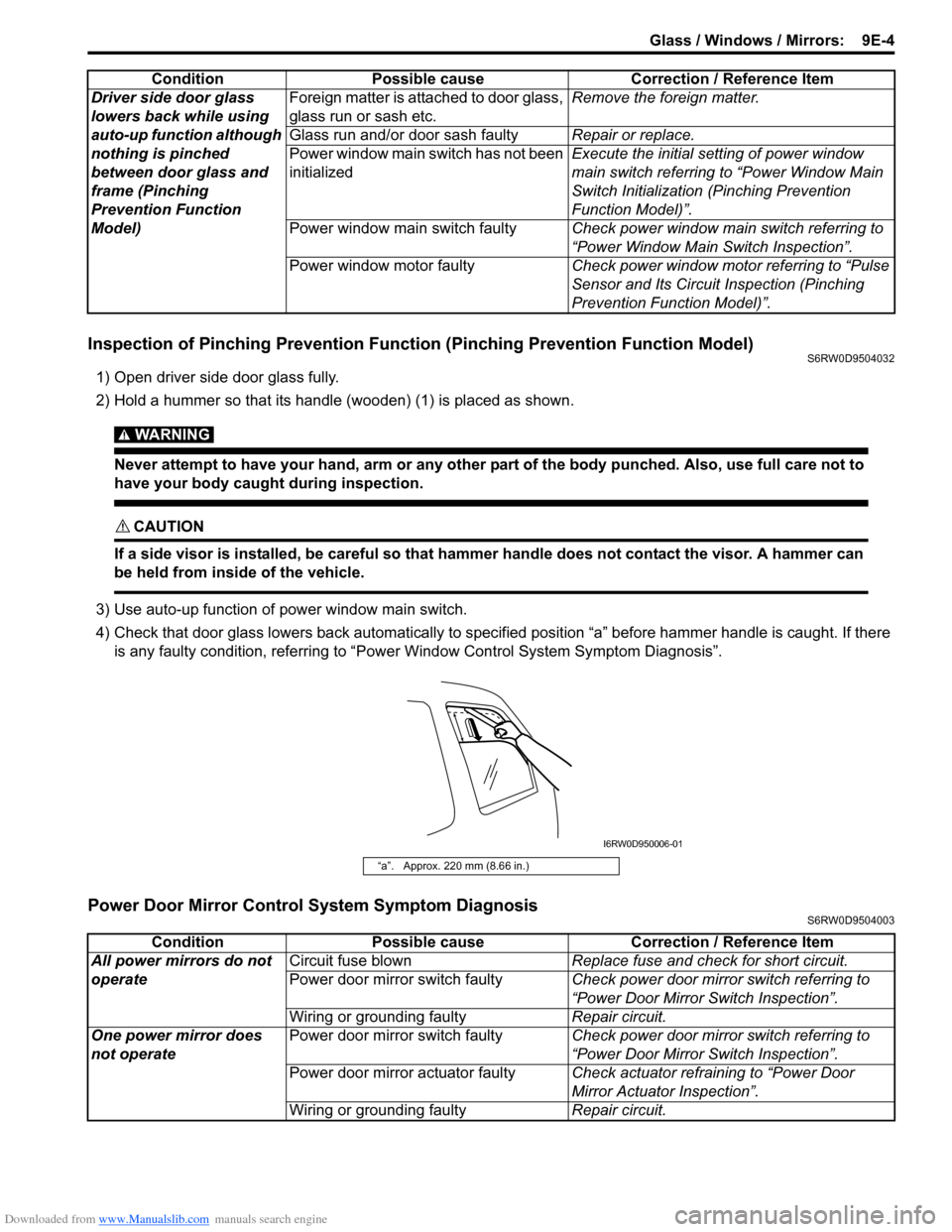
Inspection of Pinching Prevention Function (Pinching Prevention Function Model)S6RW0D9504032
1) Open driver side door glass fully.
2) Hold a hummer so that its handle (wooden) (1) is placed as shown.
WARNING!
Never attempt to have your hand, arm or any other part of the body punched. Also, use full care not to
have your body caught during inspection.
CAUTION!
If a side visor is installed, be careful so that hammer handle does not contact the visor. A hammer can
be held from inside of the vehicle.
3) Use auto-up function of power window main switch.
4) Check that door glass lowers back automatically to specified position “a” before hammer handle is caught. If there
is any faulty condition, referring to “Power Window Control System Symptom Diagnosis”.
Power Door Mirror Control System Symptom DiagnosisS6RW0D9504003
Driver side door glass
lowers back while using
auto-up function although
nothing is pinched
between door glass and
frame (Pinching
Prevention Function
Model)Foreign matter is attached to door glass,
glass run or sash etc.Remove the foreign matter.
Glass run and/or door sash faultyRepair or replace.
Power window main switch has not been
initializedExecute the initial setting of power window
main switch referring to “Power Window Main
Switch Initialization (Pinching Prevention
Function Model)”.
Power window main switch faultyCheck power window main switch referring to
“Power Window Main Switch Inspection”.
Power window motor faultyCheck power window motor referring to “Pulse
Sensor and Its Circuit Inspection (Pinching
Prevention Function Model)”. Condition Possible cause Correction / Reference Item
“a”. Approx. 220 mm (8.66 in.)
I6RW0D950006-01
Condition Possible cause Correction / Reference Item
All power mirrors do not
operateCircuit fuse blownReplace fuse and check for short circuit.
Power door mirror switch faultyCheck power door mirror switch referring to
“Power Door Mirror Switch Inspection”.
Wiring or grounding faultyRepair circuit.
One power mirror does
not operatePower door mirror switch faultyCheck power door mirror switch referring to
“Power Door Mirror Switch Inspection”.
Power door mirror actuator faultyCheck actuator refraining to “Power Door
Mirror Actuator Inspection”.
Wiring or grounding faultyRepair circuit.
Page 1400 of 1556
Downloaded from www.Manualslib.com manuals search engine 9E-15 Glass / Windows / Mirrors:
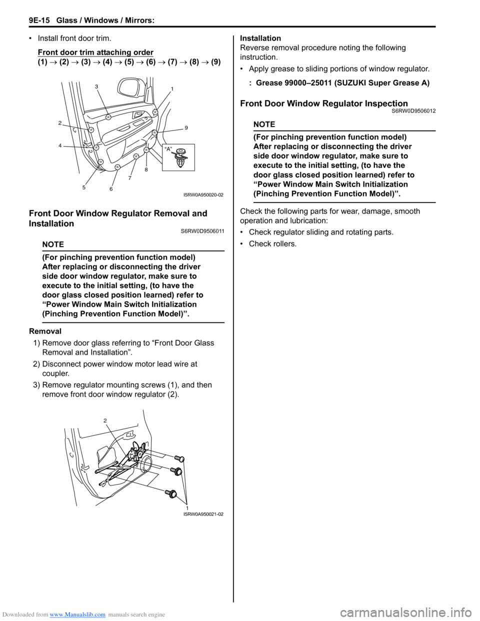
• Install front door trim.
Front door trim attaching order
(1) → (2) → (3) → (4) → (5) → (6) → (7) → (8) → (9)
Front Door Window Regulator Removal and
Installation
S6RW0D9506011
NOTE
(For pinching prevention function model)
After replacing or disconnecting the driver
side door window regulator, make sure to
execute to the initial setting, (to have the
door glass closed position learned) refer to
“Power Window Main Switch Initialization
(Pinching Prevention Function Model)”.
Removal
1) Remove door glass referring to “Front Door Glass
Removal and Installation”.
2) Disconnect power window motor lead wire at
coupler.
3) Remove regulator mounting screws (1), and then
remove front door window regulator (2).Installation
Reverse removal procedure noting the following
instruction.
• Apply grease to sliding portions of window regulator.
: Grease 99000–25011 (SUZUKI Super Grease A)
Front Door Window Regulator InspectionS6RW0D9506012
NOTE
(For pinching prevention function model)
After replacing or disconnecting the driver
side door window regulator, make sure to
execute to the initial setting, (to have the
door glass closed position learned) refer to
“Power Window Main Switch Initialization
(Pinching Prevention Function Model)”.
Check the following parts for wear, damage, smooth
operation and lubrication:
• Check regulator sliding and rotating parts.
• Check rollers.
“A”
“A”
“A”
“A”“A”
“A”“A”
“A”
“A”
“A”
3
2
4
5
6
7
8
9
1
I5RW0A950020-02
2
1I5RW0A950021-02
Page 1403 of 1556
Downloaded from www.Manualslib.com manuals search engine Glass / Windows / Mirrors: 9E-18
Rear Door Window Regulator Removal and
Installation
S6RW0D9506015
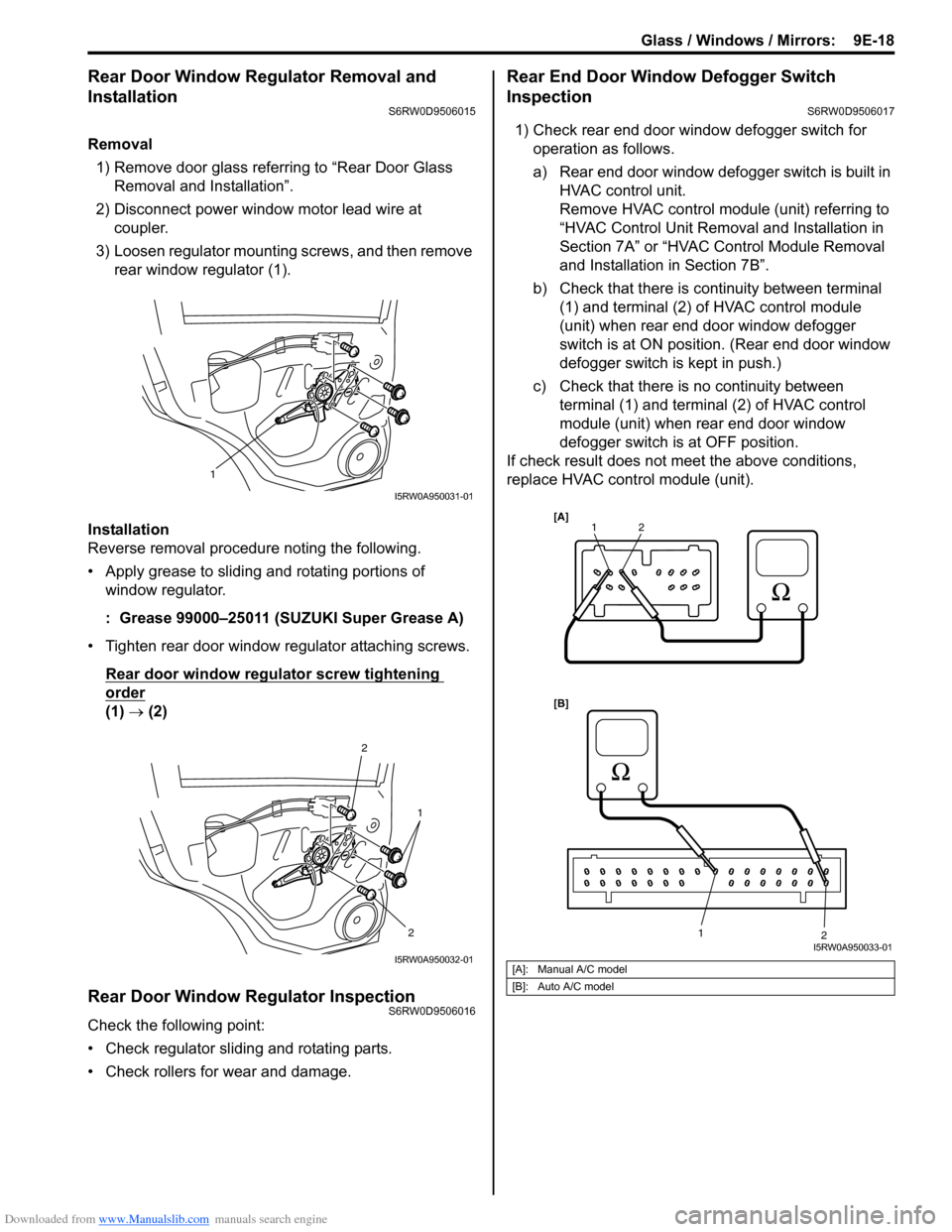
Removal
1) Remove door glass referring to “Rear Door Glass
Removal and Installation”.
2) Disconnect power window motor lead wire at
coupler.
3) Loosen regulator mounting screws, and then remove
rear window regulator (1).
Installation
Reverse removal procedure noting the following.
• Apply grease to sliding and rotating portions of
window regulator.
: Grease 99000–25011 (SUZUKI Super Grease A)
• Tighten rear door window regulator attaching screws.
Rear door window regulator screw tightening
order
(1) → (2)
Rear Door Window Regulator InspectionS6RW0D9506016
Check the following point:
• Check regulator sliding and rotating parts.
• Check rollers for wear and damage.
Rear End Door Window Defogger Switch
Inspection
S6RW0D9506017
1) Check rear end door window defogger switch for
operation as follows.
a) Rear end door window defogger switch is built in
HVAC control unit.
Remove HVAC control module (unit) referring to
“HVAC Control Unit Removal and Installation in
Section 7A” or “HVAC Control Module Removal
and Installation in Section 7B”.
b) Check that there is continuity between terminal
(1) and terminal (2) of HVAC control module
(unit) when rear end door window defogger
switch is at ON position. (Rear end door window
defogger switch is kept in push.)
c) Check that there is no continuity between
terminal (1) and terminal (2) of HVAC control
module (unit) when rear end door window
defogger switch is at OFF position.
If check result does not meet the above conditions,
replace HVAC control module (unit).
1
I5RW0A950031-01
2
2
1
I5RW0A950032-01[A]: Manual A/C model
[B]: Auto A/C model
1
1 2
2[A]
[B]
I5RW0A950033-01