2006 SUZUKI SX4 Motor
[x] Cancel search: MotorPage 1408 of 1556
Downloaded from www.Manualslib.com manuals search engine 9E-23 Glass / Windows / Mirrors:
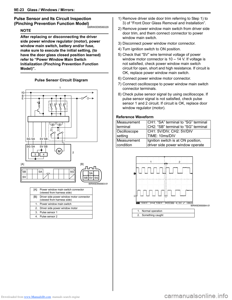
Pulse Sensor and Its Circuit Inspection
(Pinching Prevention Function Model)
S6RW0D9506029
NOTE
After replacing or disconnecting the driver
side power window regulator (motor), power
window main switch, battery and/or fuse,
make sure to execute the initial setting, (to
have the door glass closed position learned)
refer to “Power Window Main Switch
Initialization (Pinching Prevention Function
Model)”.
Pulse Sensor Circuit Diagram1) Remove driver side door trim referring to Step 1) to
3) of “Front Door Glass Removal and Installation”.
2) Remove power window main switch from driver side
door trim, and them connect connector to power
window main switch.
3) Disconnect power window motor connector.
4) Turn ignition switch to ON position.
5) Check that “SV” wire terminal voltage of power
window motor connector is 10 – 14 V. If voltage is
not satisfied, check power window main switch
circuit for open, short and high resistance. If circuit is
OK, replace power window main switch.
6) Connect power window motor connector.
7) Connect oscilloscope to power window main switch
connector terminals.
8) Check pulse sensor signal by using oscilloscope. If
pulse sensor signal is not satisfied, check pulse
sensor 1 and 2 circuit. If circuit is OK, replace door
window regulator (motor).
Reference Waveform
[A]: Power window main switch connector
(viewed from harness side)
[B]: Driver side power window motor connector
(viewed from harness side)
1. Power window main switch
2. Driver side power window motor
3. Pulse sensor 1
4. Pulse sensor 2
SG
SV SB SA
SG SV SBSA
B IG
E
4 3
SG SV SBSA
SG SV SBSA
2 1
[A] [B]
I6RW0D950003-01
Measurement
terminalCH1: “SA” terminal to “SG” terminal
CH2: “SB” terminal to “SG” terminal
Oscilloscope
settingCH1: 5V/DIV, CH2: 5V/DIV
TIME: 10ms/DIV
Measurement
conditionIgnition switch is at ON position,
driver side power window operate
1. Normal operation
2. Something caught
I6RW0D950004-01
Page 1409 of 1556
Downloaded from www.Manualslib.com manuals search engine Glass / Windows / Mirrors: 9E-24
Power Window Main Switch Initialization
(Pinching Prevention Function Model)
S6RW0D9506030
CAUTION!
• After replacing or disconnecting the driver
side door window regulator (motor), power
window main switch, battery or fuse, be
sure to execute initial setting (to have door
glass completely closed position learned).
If initial setting is not executed, correct
automatic operation (including pinching
prevention operation) would not be
available.
• Make sure that no foreign matter is
pinched while executing initial setting.
1) Open driver side door glass fully.
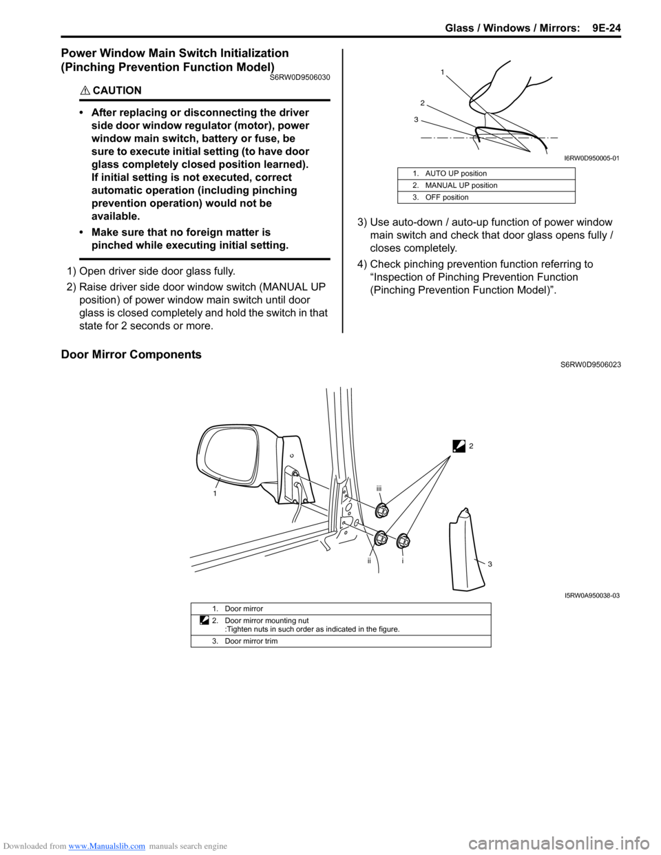
2) Raise driver side door window switch (MANUAL UP
position) of power window main switch until door
glass is closed completely and hold the switch in that
state for 2 seconds or more.3) Use auto-down / auto-up function of power window
main switch and check that door glass opens fully /
closes completely.
4) Check pinching prevention function referring to
“Inspection of Pinching Prevention Function
(Pinching Prevention Function Model)”.
Door Mirror ComponentsS6RW0D9506023 1. AUTO UP position
2. MANUAL UP position
3. OFF position
1
2
3
I6RW0D950005-01
2
1
i
iiiii
3
I5RW0A950038-03
1. Door mirror
2. Door mirror mounting nut
:Tighten nuts in such order as indicated in the figure.
3. Door mirror trim
Page 1417 of 1556
Downloaded from www.Manualslib.com manuals search engine Security and Locks: 9F-6
Repair Instructions
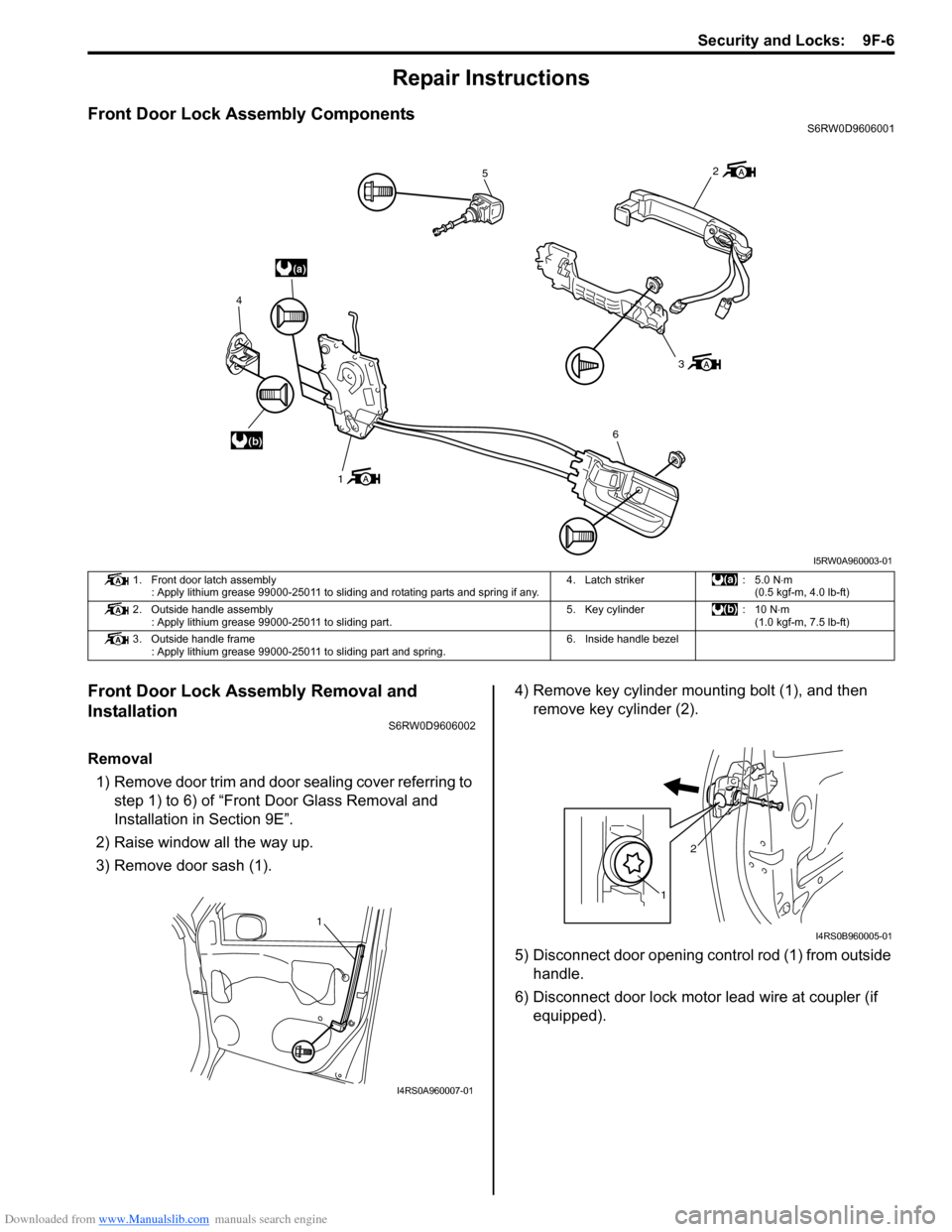
Front Door Lock Assembly ComponentsS6RW0D9606001
Front Door Lock Assembly Removal and
Installation
S6RW0D9606002
Removal
1) Remove door trim and door sealing cover referring to
step 1) to 6) of “Front Door Glass Removal and
Installation in Section 9E”.
2) Raise window all the way up.
3) Remove door sash (1).4) Remove key cylinder mounting bolt (1), and then
remove key cylinder (2).
5) Disconnect door opening control rod (1) from outside
handle.
6) Disconnect door lock motor lead wire at coupler (if
equipped).
(a)
(b)
5
3
6
1 4
2
I5RW0A960003-01
1. Front door latch assembly
: Apply lithium grease 99000-25011 to sliding and rotating parts and spring if any.4. Latch striker : 5.0 N⋅m
(0.5 kgf-m, 4.0 lb-ft)
2. Outside handle assembly
: Apply lithium grease 99000-25011 to sliding part.5. Key cylinder : 10 N⋅m
(1.0 kgf-m, 7.5 lb-ft)
3. Outside handle frame
: Apply lithium grease 99000-25011 to sliding part and spring.6. Inside handle bezel
1
I4RS0A960007-01
12
I4RS0B960005-01
Page 1421 of 1556
Downloaded from www.Manualslib.com manuals search engine Security and Locks: 9F-10
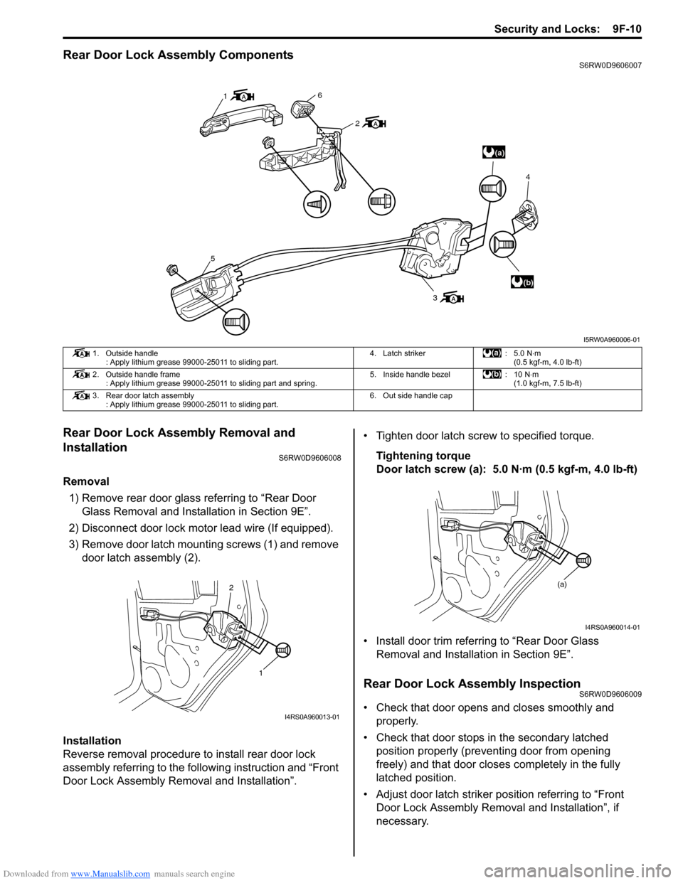
Rear Door Lock Assembly ComponentsS6RW0D9606007
Rear Door Lock Assembly Removal and
Installation
S6RW0D9606008
Removal
1) Remove rear door glass referring to “Rear Door
Glass Removal and Installation in Section 9E”.
2) Disconnect door lock motor lead wire (If equipped).
3) Remove door latch mounting screws (1) and remove
door latch assembly (2).
Installation
Reverse removal procedure to install rear door lock
assembly referring to the following instruction and “Front
Door Lock Assembly Removal and Installation”.• Tighten door latch screw to specified torque.
Tightening torque
Door latch screw (a): 5.0 N·m (0.5 kgf-m, 4.0 lb-ft)
• Install door trim referring to “Rear Door Glass
Removal and Installation in Section 9E”.
Rear Door Lock Assembly InspectionS6RW0D9606009
• Check that door opens and closes smoothly and
properly.
• Check that door stops in the secondary latched
position properly (preventing door from opening
freely) and that door closes completely in the fully
latched position.
• Adjust door latch striker position referring to “Front
Door Lock Assembly Removal and Installation”, if
necessary.
(a)
(b) 1
6
2
5
34
I5RW0A960006-01
1. Outside handle
: Apply lithium grease 99000-25011 to sliding part.4. Latch striker : 5.0 N⋅m
(0.5 kgf-m, 4.0 lb-ft)
2. Outside handle frame
: Apply lithium grease 99000-25011 to sliding part and spring.5. Inside handle bezel : 10 N⋅m
(1.0 kgf-m, 7.5 lb-ft)
3. Rear door latch assembly
: Apply lithium grease 99000-25011 to sliding part.6. Out side handle cap
1 2
I4RS0A960013-01
(a)
I4RS0A960014-01
Page 1423 of 1556
Downloaded from www.Manualslib.com manuals search engine Security and Locks: 9F-12
Rear End Door Lock Assembly Removal and
Installation
S6RW0D9606011
Removal
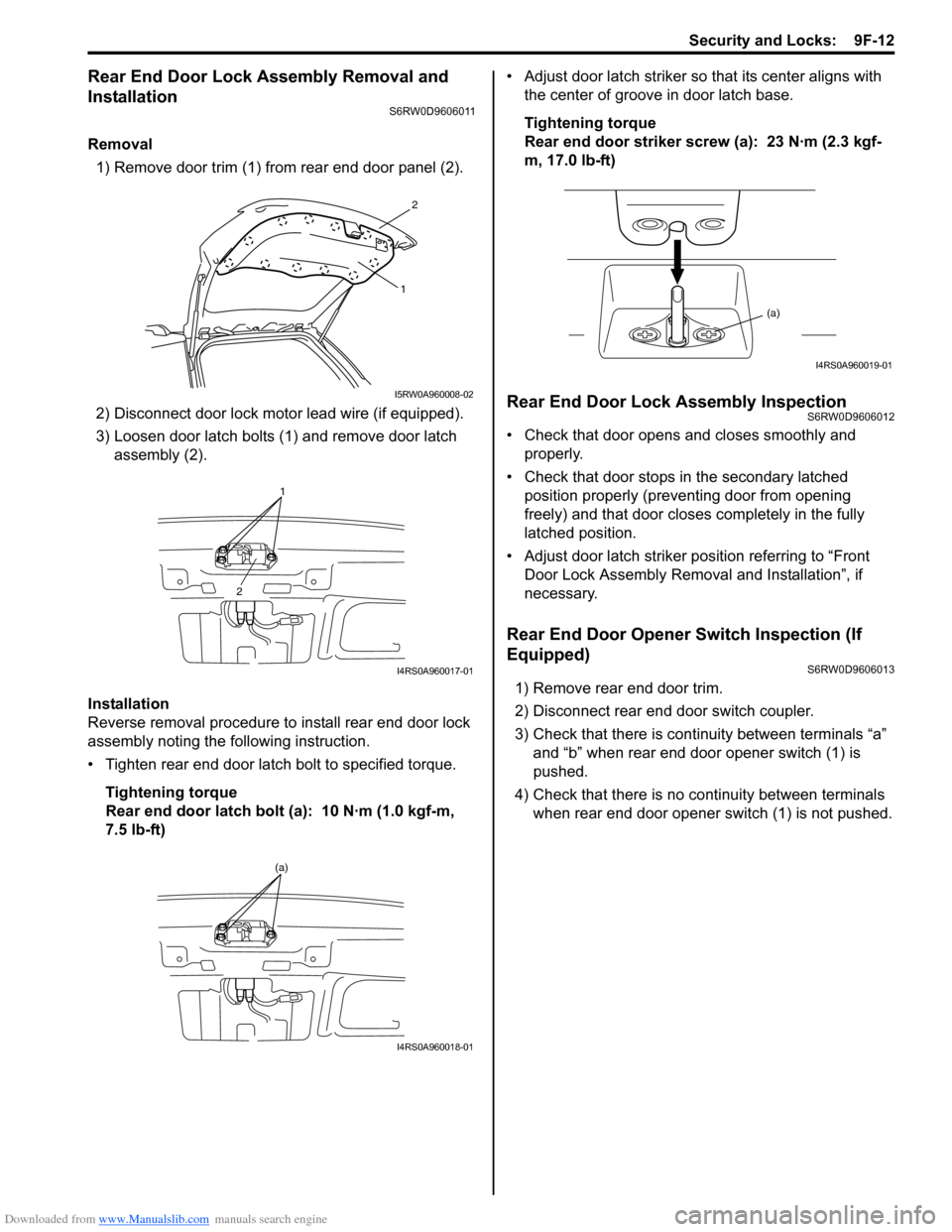
1) Remove door trim (1) from rear end door panel (2).
2) Disconnect door lock motor lead wire (if equipped).
3) Loosen door latch bolts (1) and remove door latch
assembly (2).
Installation
Reverse removal procedure to install rear end door lock
assembly noting the following instruction.
• Tighten rear end door latch bolt to specified torque.
Tightening torque
Rear end door latch bolt (a): 10 N·m (1.0 kgf-m,
7.5 lb-ft)• Adjust door latch striker so that its center aligns with
the center of groove in door latch base.
Tightening torque
Rear end door striker screw (a): 23 N·m (2.3 kgf-
m, 17.0 lb-ft)
Rear End Door Lock Assembly InspectionS6RW0D9606012
• Check that door opens and closes smoothly and
properly.
• Check that door stops in the secondary latched
position properly (preventing door from opening
freely) and that door closes completely in the fully
latched position.
• Adjust door latch striker position referring to “Front
Door Lock Assembly Removal and Installation”, if
necessary.
Rear End Door Opener Switch Inspection (If
Equipped)
S6RW0D9606013
1) Remove rear end door trim.
2) Disconnect rear end door switch coupler.
3) Check that there is continuity between terminals “a”
and “b” when rear end door opener switch (1) is
pushed.
4) Check that there is no continuity between terminals
when rear end door opener switch (1) is not pushed.
2
1
I5RW0A960008-02
1
2
I4RS0A960017-01
(a)
I4RS0A960018-01
(a)
I4RS0A960019-01
Page 1478 of 1556
Downloaded from www.Manualslib.com manuals search engine 10B-5 Body Electrical Control System:
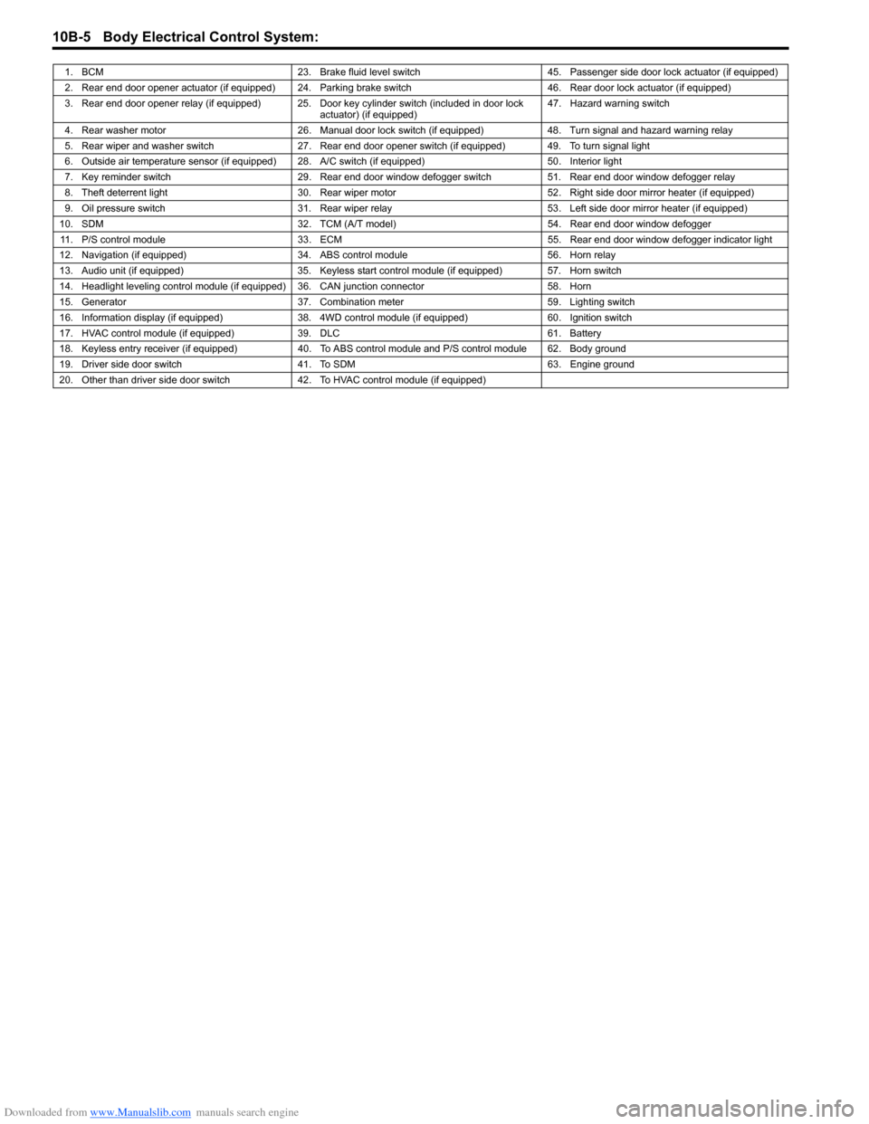
1. BCM 23. Brake fluid level switch 45. Passenger side door lock actuator (if equipped)
2. Rear end door opener actuator (if equipped) 24. Parking brake switch 46. Rear door lock actuator (if equipped)
3. Rear end door opener relay (if equipped) 25. Door key cylinder switch (included in door lock
actuator) (if equipped)47. Hazard warning switch
4. Rear washer motor 26. Manual door lock switch (if equipped) 48. Turn signal and hazard warning relay
5. Rear wiper and washer switch 27. Rear end door opener switch (if equipped) 49. To turn signal light
6. Outside air temperature sensor (if equipped) 28. A/C switch (if equipped) 50. Interior light
7. Key reminder switch 29. Rear end door window defogger switch 51. Rear end door window defogger relay
8. Theft deterrent light 30. Rear wiper motor 52. Right side door mirror heater (if equipped)
9. Oil pressure switch 31. Rear wiper relay 53. Left side door mirror heater (if equipped)
10. SDM 32. TCM (A/T model) 54. Rear end door window defogger
11. P/S control module 33. ECM 55. Rear end door window defogger indicator light
12. Navigation (if equipped) 34. ABS control module 56. Horn relay
13. Audio unit (if equipped) 35. Keyless start control module (if equipped) 57. Horn switch
14. Headlight leveling control module (if equipped) 36. CAN junction connector 58. Horn
15. Generator 37. Combination meter 59. Lighting switch
16. Information display (if equipped) 38. 4WD control module (if equipped) 60. Ignition switch
17. HVAC control module (if equipped) 39. DLC 61. Battery
18. Keyless entry receiver (if equipped) 40. To ABS control module and P/S control module 62. Body ground
19. Driver side door switch 41. To SDM 63. Engine ground
20. Other than driver side door switch 42. To HVAC control module (if equipped)
Page 1479 of 1556
Downloaded from www.Manualslib.com manuals search engine Body Electrical Control System: 10B-6
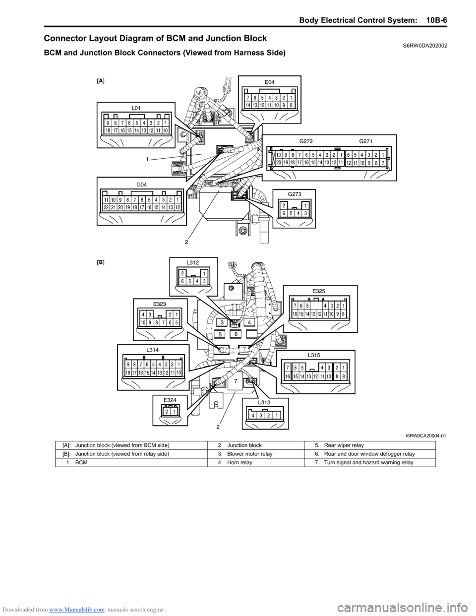
Connector Layout Diagram of BCM and Junction BlockS6RW0DA202002
BCM and Junction Block Connectors (Viewed from Harness Side)
I6RW0CA20004-01
[A]: Junction block (viewed from BCM side) 2. Junction block 5. Rear wiper relay
[B]: Junction block (viewed from relay side) 3. Blower motor relay 6. Rear end door window defogger relay
1. BCM 4. Horn relay 7. Turn signal and hazard warning relay
Page 1495 of 1556
Downloaded from www.Manualslib.com manuals search engine Body Electrical Control System: 10B-22
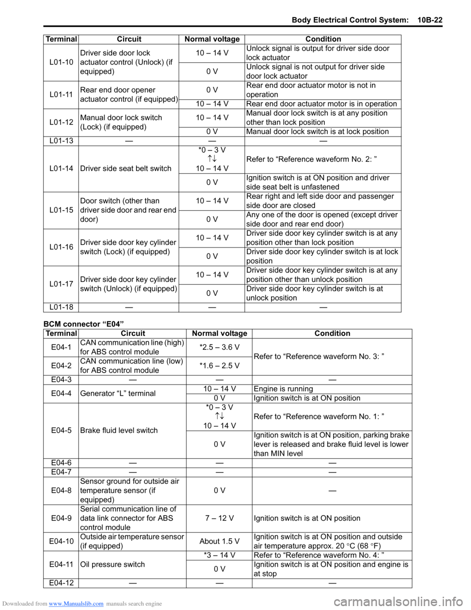
BCM connector “E04”L01-10Driver side door lock
actuator control (Unlock) (if
equipped)10 – 14 VUnlock signal is output for driver side door
lock actuator
0 VUnlock signal is not output for driver side
door lock actuator
L01-11Rear end door opener
actuator control (if equipped)0 VRear end door actuator motor is not in
operation
10 – 14 V Rear end door actuator motor is in operation
L01-12Manual door lock switch
(Lock) (if equipped)10 – 14 VManual door lock switch is at any position
other than lock position
0 V Manual door lock switch is at lock position
L01-13 — — —
L01-14 Driver side seat belt switch*0 – 3 V
↑↓
10 – 14 VRefer to “Reference waveform No. 2: ”
0 VIgnition switch is at ON position and driver
side seat belt is unfastened
L01-15Door switch (other than
driver side door and rear end
door)10 – 14 VRear right and left side door and passenger
side door are closed
0 VAny one of the door is opened (except driver
side door and rear end door)
L01-16Driver side door key cylinder
switch (Lock) (if equipped)10 – 14 VDriver side door key cylinder switch is at any
position other than lock position
0 VDriver side door key cylinder switch is at lock
position
L01-17Driver side door key cylinder
switch (Unlock) (if equipped)10 – 14 VDriver side door key cylinder switch is at any
position other than unlock position
0 VDriver side door key cylinder switch is at
unlock position
L01-18 — — —
Terminal Circuit Normal voltage Condition
E04-1CAN communication line (high)
for ABS control module*2.5 – 3.6 V
Refer to “Reference waveform No. 3: ”
E04-2CAN communication line (low)
for ABS control module*1.6 – 2.5 V
E04-3 — — —
E04-4 Generator “L” terminal10 – 14 V Engine is running
0 V Ignition switch is at ON position
E04-5 Brake fluid level switch*0 – 3 V
↑↓
10 – 14 VRefer to “Reference waveform No. 1: ”
0 VIgnition switch is at ON position, parking brake
lever is released and brake fluid level is lower
than MIN level
E04-6 — — —
E04-7 — — —
E04-8Sensor ground for outside air
temperature sensor (if
equipped)0 V —
E04-9Serial communication line of
data link connector for ABS
control module7 – 12 V Ignition switch is at ON position
E04-10Outside air temperature sensor
(if equipped)About 1.5 VIgnition switch is at ON position and outside
air temperature approx. 20 °C (68
°F)
E04-11 Oil pressure switch*3 – 14 V Refer to “Reference waveform No. 4: ”
0 VIgnition switch is at ON position and engine is
at stop
E04-12 — — — Terminal Circuit Normal voltage Condition