2006 SUZUKI SX4 backup light
[x] Cancel search: backup lightPage 57 of 1556

Downloaded from www.Manualslib.com manuals search engine Engine General Information and Diagnosis: 1A-7
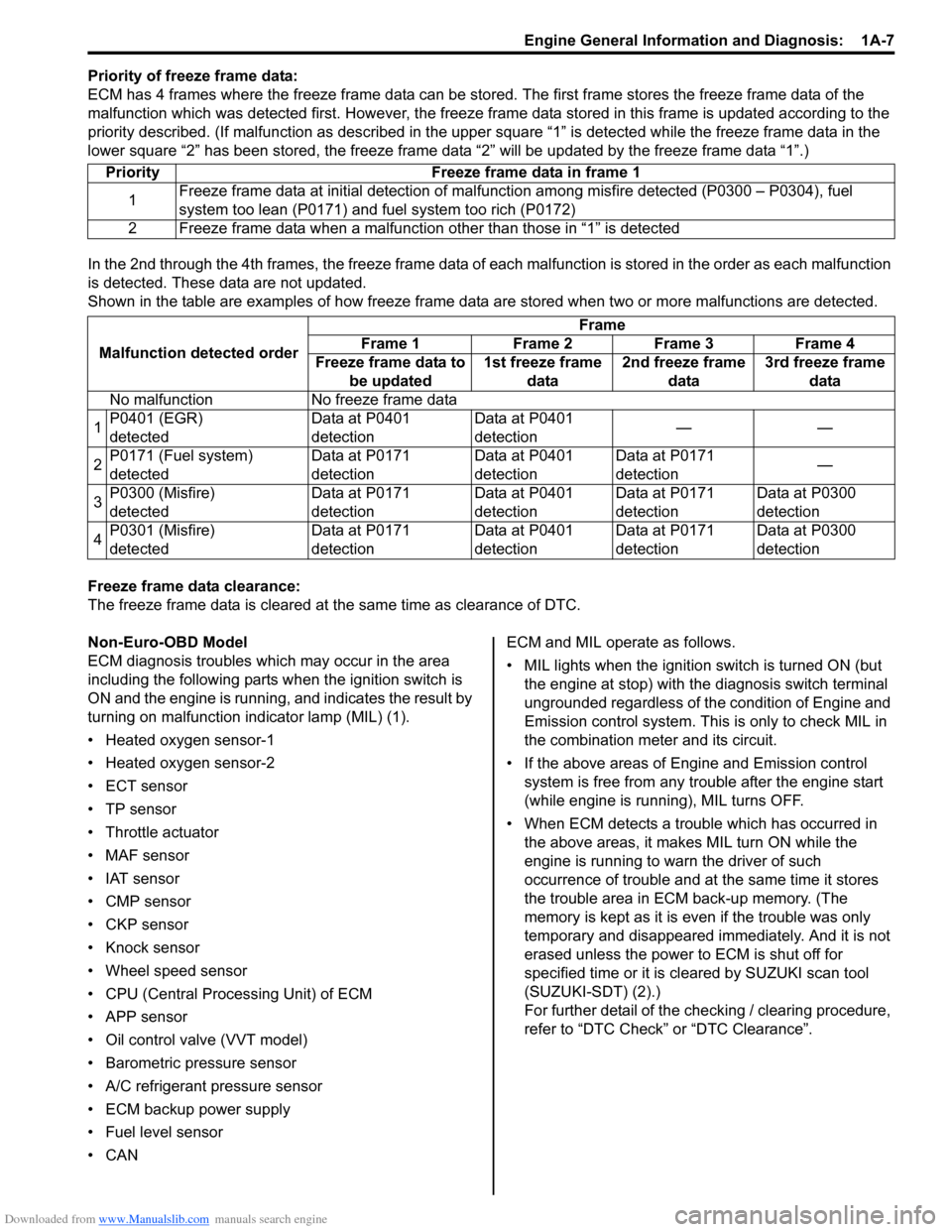
Priority of freeze frame data:
ECM has 4 frames where the freeze frame data can be stored. The first frame stores the freeze frame data of the
malfunction which was detected first. However, the freeze frame data stored in this frame is updated according to the
priority described. (If malfunction as described in the upper square “1” is detected while the freeze frame data in the
lower square “2” has been stored, the freeze frame data “2” will be updated by the freeze frame data “1”.)
In the 2nd through the 4th frames, the freeze frame data of each malfunction is stored in the order as each malfunction
is detected. These data are not updated.
Shown in the table are examples of how freeze frame data are stored when two or more malfunctions are detected.
Freeze frame data clearance:
The freeze frame data is cleared at the same time as clearance of DTC.
Non-Euro-OBD Model
ECM diagnosis troubles which may occur in the area
including the following parts when the ignition switch is
ON and the engine is running, and indicates the result by
turning on malfunction indicator lamp (MIL) (1).
• Heated oxygen sensor-1
• Heated oxygen sensor-2
• ECT sensor
•TP sensor
• Throttle actuator
• MAF sensor
• IAT sensor
• CMP sensor
• CKP sensor
• Knock sensor
• Wheel speed sensor
• CPU (Central Processing Unit) of ECM
• APP sensor
• Oil control valve (VVT model)
• Barometric pressure sensor
• A/C refrigerant pressure sensor
• ECM backup power supply
• Fuel level sensor
•CANECM and MIL operate as follows.
• MIL lights when the ignition switch is turned ON (but
the engine at stop) with the diagnosis switch terminal
ungrounded regardless of the condition of Engine and
Emission control system. This is only to check MIL in
the combination meter and its circuit.
• If the above areas of Engine and Emission control
system is free from any trouble after the engine start
(while engine is running), MIL turns OFF.
• When ECM detects a trouble which has occurred in
the above areas, it makes MIL turn ON while the
engine is running to warn the driver of such
occurrence of trouble and at the same time it stores
the trouble area in ECM back-up memory. (The
memory is kept as it is even if the trouble was only
temporary and disappeared immediately. And it is not
erased unless the power to ECM is shut off for
specified time or it is cleared by SUZUKI scan tool
(SUZUKI-SDT) (2).)
For further detail of the checking / clearing procedure,
refer to “DTC Check” or “DTC Clearance”. Priority Freeze frame data in frame 1
1Freeze frame data at initial detection of malfunction among misfire detected (P0300 – P0304), fuel
system too lean (P0171) and fuel system too rich (P0172)
2 Freeze frame data when a malfunction other than those in “1” is detected
Malfunction detected orderFrame
Frame 1 Frame 2 Frame 3 Frame 4
Freeze frame data to
be updated1st freeze frame
data2nd freeze frame
data3rd freeze frame
data
No malfunction No freeze frame data
1P0401 (EGR)
detectedData at P0401
detectionData at P0401
detection——
2P0171 (Fuel system)
detectedData at P0171
detectionData at P0401
detectionData at P0171
detection—
3P0300 (Misfire)
detectedData at P0171
detectionData at P0401
detectionData at P0171
detectionData at P0300
detection
4P0301 (Misfire)
detectedData at P0171
detectionData at P0401
detectionData at P0171
detectionData at P0300
detection
Page 658 of 1556

Downloaded from www.Manualslib.com manuals search engine 5A-10 Automatic Transmission/Transaxle:
Schematic and Routing Diagram
Transmission Control Module (TCM) Wiring DiagramS6RW0D5102001
12V
12V
12V
IG1
118
9
10
P
R
N
D
2
L12
2.5V
5V
12V
5V
12V
12V
12V
WHT
BLK
BLK
BLK
BLK
PPLBLK/WHT
BLK/ORN
IG11
RED/BLK
YEL/BLKYEL/BLU
LT GRN/BLK
+BB
WHT/RED
14
20 15
16
17
19
12V18
1 2
3
132126
24 27
28
29
30
65
16 15 14 13 12 1143
24 23 212210 9 8 721
19 20 18 17 C06
17 16
26 2515 14 65 342
13 12
23 22 2411 10 9
21 20 1987
18 1 C07
[A]
22
25
YELYEL/GRN
WHT
P
N
BRN LT/GRN
ORN
BLK/YEL
BLU/BLK
GRY
LT GRN/BLKWHT/BLU
WHT/BLK
C06-11
C06-12
C06-16
C06-15
C06-14
C06-4
C06-2
C06-1
C06-23C06-6 C06-24C06-5
C06-3
RED
GRN GRN/ORNPNK/BLK
GRN/YEL
LT GRN/BLKC07-6
C07-16
C07-23 C07-25
C07-20
C07-1
C07-8
C07-7
C07-19
C07-18
4IG11 23
C07-9
YEL
RED
WHTBLU35 34
3637
5REDWHT
7
WHT
RED
33
4
6
C06-7C06-17WHT
REDREDWHT
WHT
12V12V
WHTRED
WHTREDREDWHT
31
32
RED
WHTRED[B]
[C]
I6RW0D510003-02
1. TCM 15. Shift solenoid valve-A (No.1) 29. “ST SIG” fuse
2. Input shaft speed sensor 16. Shift solenoid valve-B (No.2) 30. “ST” fuse
3. Output shaft speed sensor / VSS 17. Timing solenoid valve 31. MIL
4. ECM 18. TCC solenoid valve 32. Transmission warning light (non-Euro-OBD model)
5. Combination meter 19. Pressure control solenoid valve 33. ABS control module
6. BCM 20. A/T 34. To Data link connector
7. 4WD control module (if equipped) 21. A/T relay 35. To BCM
8. “3” position switch 22. Inhibitor switch (including transmission range
sensor)36. Junction connector
9. Shift lock solenoid 23. Starter motor relay 37. Keyless start control module (if equipped)
10. Brake light switch 24. Ignition switch [A]: Terminal arrangement of TCM connector (viewed
from harness side)
11. Transmission range sensor 25. Starter motor [B]: Junction block with BCM model
12. Backup lamp 26. “DOME” fuse [C]: Junction block without BCM model
13. Data link connector (DLC) 27. “AT” fuse
14. Transmission fluid temperature sensor 28. “IG1 SIG” fuse
Page 1058 of 1556

Downloaded from www.Manualslib.com manuals search engine 8B-19 Air Bag System:
Scan Tool Data Definition
Buck Up Volt (V)
This parameter indicates the capacity of the backup
capacitor installed to maintain the ignition current (as
much as possible) even when the power supply to SDM
that ignites the inflator is shut off.
Battery Voltage (V)
Battery voltage is an analog input signal read by SDM.
Dirv Air Bag Ini Res (Driver air bag initiator
resistance) (ohm)
This parameter indicates the resistance of the driver air
bag initiator circuit.
Pass Air Bag Ini Res (Passenger air bag initiator
resistance) (ohm)
This parameter indicates the resistance of the passenger
air bag initiator circuit.
Driv Preten Ini Res (Driver pretensioner initiator
resistance) (ohm)
This parameter indicates the resistance of the driver seat
belt pretensioner initiator circuit.Pass Preten Ini Res (Passenger pretensioner
initiator resistance) (ohm)
This parameter indicates the resistance of the passenger
seat belt pretensioner initiator circuit.
Driv Sidebag Ini Res (Driver side-air bag initiator
resistance) (ohm)
This parameter indicates the resistance of the driver
side-air bag initiator circuit.
Pass Sidebag Ini Res (Passenger side-air bag
initiator resistance) (ohm)
This parameter indicates the resistance of the passenger
side-air bag initiator circuit.
Driv curtain Ini RES (Driver side curtain-air bag
initiator resistance) (ohm)
This parameter indicates the resistance of the driver side
curtain-air bag initiator circuit.
Pass curtain Ini RES (Passenger side curtain-air bag
initiator resistance) (ohm)
This parameter indicates the resistance of the passenger
side curtain-air bag initiator circuit.
System ID (4ch/8ch)
This parameter indicates the number of initiator circuits.
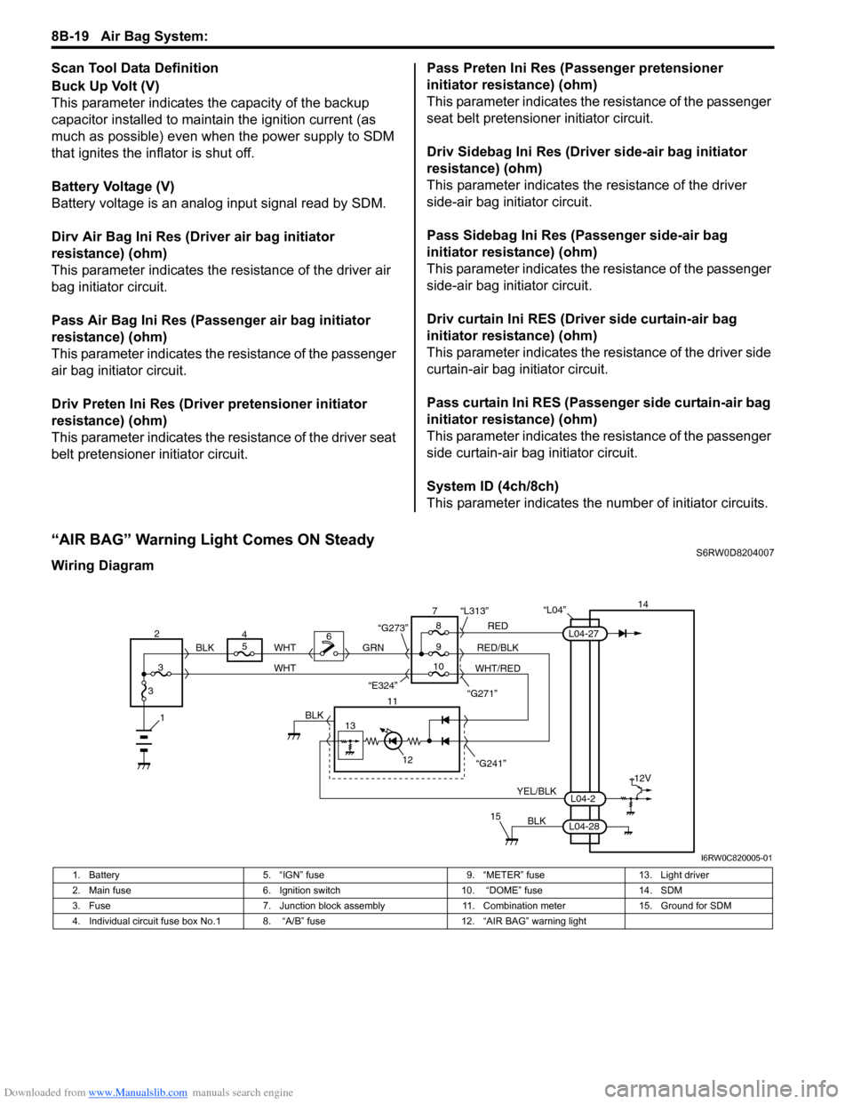
“AIR BAG” Warning Light Comes ON SteadyS6RW0D8204007
Wiring Diagram
“L04”14
5
9RED
RED/BLK GRN
YEL/BLK
BLK
8 7
11
12
15
L04-2
L04-28
L04-27
“G241” “G271” “L313”
13
12V
6
1BLK
WHT WHT
WHT/RED 2
34
310 BLK
“G273”
“E324”
I6RW0C820005-01
1. Battery 5. “IGN” fuse 9. “METER” fuse 13. Light driver
2. Main fuse 6. Ignition switch 10. “DOME” fuse 14. SDM
3. Fuse 7. Junction block assembly 11. Combination meter 15. Ground for SDM
4. Individual circuit fuse box No.1 8. “A/B” fuse 12. “AIR BAG” warning light
Page 1497 of 1556

Downloaded from www.Manualslib.com manuals search engine Body Electrical Control System: 10B-24
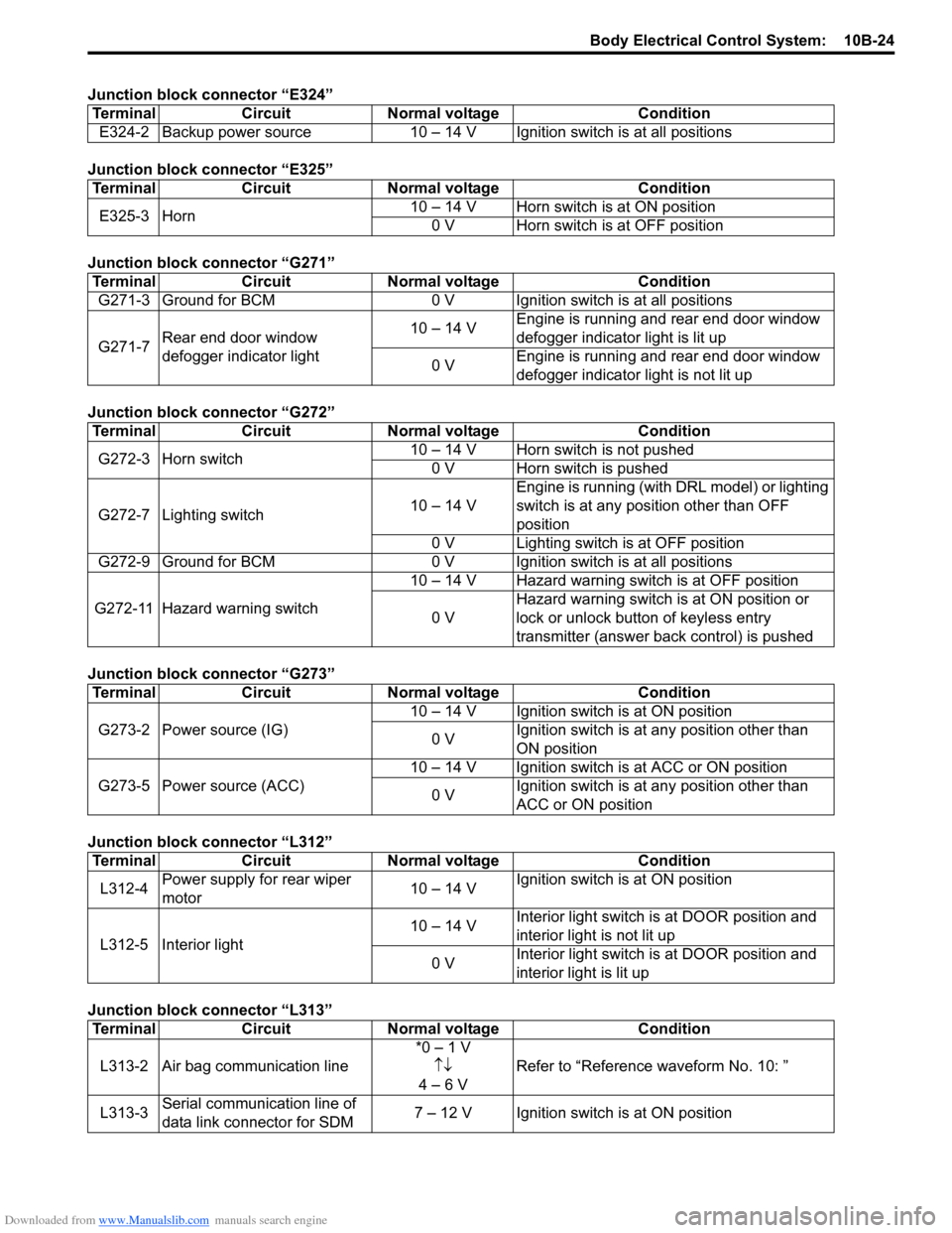
Junction block connector “E324”
Junction block connector “E325”
Junction block connector “G271”
Junction block connector “G272”
Junction block connector “G273”
Junction block connector “L312”
Junction block connector “L313”Terminal Circuit Normal voltage Condition
E324-2 Backup power source 10 – 14 V Ignition switch is at all positions
Terminal Circuit Normal voltage Condition
E325-3 Horn10 – 14 V Horn switch is at ON position
0 V Horn switch is at OFF position
Terminal Circuit Normal voltage Condition
G271-3 Ground for BCM 0 V Ignition switch is at all positions
G271-7Rear end door window
defogger indicator light10 – 14 VEngine is running and rear end door window
defogger indicator light is lit up
0 VEngine is running and rear end door window
defogger indicator light is not lit up
Terminal Circuit Normal voltage Condition
G272-3 Horn switch10 – 14 V Horn switch is not pushed
0 V Horn switch is pushed
G272-7 Lighting switch10 – 14 VEngine is running (with DRL model) or lighting
switch is at any position other than OFF
position
0 V Lighting switch is at OFF position
G272-9 Ground for BCM 0 V Ignition switch is at all positions
G272-11 Hazard warning switch10 – 14 V Hazard warning switch is at OFF position
0 VHazard warning switch is at ON position or
lock or unlock button of keyless entry
transmitter (answer back control) is pushed
Terminal Circuit Normal voltage Condition
G273-2 Power source (IG)10 – 14 V Ignition switch is at ON position
0 VIgnition switch is at any position other than
ON position
G273-5 Power source (ACC)10 – 14 V Ignition switch is at ACC or ON position
0 VIgnition switch is at any position other than
ACC or ON position
Terminal Circuit Normal voltage Condition
L312-4Power supply for rear wiper
motor10 – 14 VIgnition switch is at ON position
L312-5 Interior light10 – 14 VInterior light switch is at DOOR position and
interior light is not lit up
0 VInterior light switch is at DOOR position and
interior light is lit up
Terminal Circuit Normal voltage Condition
L313-2 Air bag communication line*0 – 1 V
↑↓
4 – 6 VRefer to “Reference waveform No. 10: ”
L313-3Serial communication line of
data link connector for SDM7 – 12 V Ignition switch is at ON position