2006 SUZUKI SX4 speedometer
[x] Cancel search: speedometerPage 14 of 1556
![SUZUKI SX4 2006 1.G Service Workshop Manual Downloaded from www.Manualslib.com manuals search engine 00-7 Precautions:
Precautions in Servicing 4WD ModelS6RW0D0000014
CAUTION!
• Never perform any of the following [A], [B]
and [C] types of SUZUKI SX4 2006 1.G Service Workshop Manual Downloaded from www.Manualslib.com manuals search engine 00-7 Precautions:
Precautions in Servicing 4WD ModelS6RW0D0000014
CAUTION!
• Never perform any of the following [A], [B]
and [C] types of](/manual-img/20/7612/w960_7612-13.png)
Downloaded from www.Manualslib.com manuals search engine 00-7 Precautions:
Precautions in Servicing 4WD ModelS6RW0D0000014
CAUTION!
• Never perform any of the following [A], [B]
and [C] types of service work.
If it is performed while 4WD-auto mode or
4WD-lock mode is selected, front wheels
(or rear wheels) drive rear wheels (or front
wheels) and vehicle accident, drivetrain
damage and personal injury may result.
Also, if it is performed while 2WD mode is
selected, the coupling may be damaged
because of the difference in revolution
speed between front wheels and rear
wheels.
• When testing with 2-wheel chassis
dynamometer or speedometer tester, be
sure to select 4WD system to 4WD-auto
mode or 4WD-lock mode and use 2-wheel
free roller together or make the vehicle as
front wheel drive by removing propeller
shaft.• When testing with 2-wheel brake tester, be
sure to observe the following instructions.
Otherwise, drivetrain damage and personal
injury may result.
– Shift transaxle to N (Neutral) position.
– Select 4WD system to 2WD mode.
– Run engine at specified idle speed.
– Rotate wheels (tires) by brake tester at
vehicle speed below 5 km/h (3 mile/h).
– Do not rotate wheels (tires) for 1 min. or
more.
• When using On-vehicle type wheel
balancing equipment (1), be sure to select
4WD system to 4WD-auto mode or 4WD-
lock mode and jack up all four wheels, off
the ground completely and support vehicle
with safety stands (2).
Be careful of other wheels, which will
rotate at the same time.
Using it with 2WD mode may damage
coupling.
• This vehicle should be towed under one of
the following conditions:
– With all wheels on a flatbed truck.
– With all wheels on the ground.
Precautions for Catalytic ConverterS6RW0D0000004
For vehicles equipped with a catalytic converter, use
only unleaded gasoline and be careful not to let a large
amount of unburned gasoline enter the converter or it
can be damaged.
• Conduct a spark jump test only when necessary,
make it as short as possible, and do not open the
throttle.
• Conduct engine compression checks within the
shortest possible time.
• Avoid situations which can result in engine misfire
(e.g. starting the engine when the fuel tank is nearly
empty.)[A]: Testing with 2-wheel chassis dynamometer or speedometer tester.
[B]: Driving front wheels, which are jacked up.
[C]: Towing under the condition where either front or rear wheels can not
rotate.
[A]
[B]
[C]
I3RH0A000004-03
I3RH01010062-01
Page 43 of 1556

Downloaded from www.Manualslib.com manuals search engine Maintenance and Lubrication: 0B-12
Steering
• Check to ensure that steering wheel is free from
instability, or abnormally heavy feeling.
• Check that the vehicle does not wander or pull to one
side.
Engine
• Check that engine responds readily at all speeds.
• Check that engine is free from abnormal noise and
abnormal vibration.
Body, Wheels and Power Transmitting System
Check that body, wheels and power transmitting system
are free from abnormal noise and abnormal vibration or
any other abnormal condition.Meters and Gauge
Check that speedometer, odometer, fuel meter,
temperature gauge, etc. are operating accurately.
Lights
Check that all lights operate properly.
Windshield Defroster
Periodically check that air comes out from defroster
outlet when operating heater or air conditioning.
Set mode control lever to defroster position and fan
switch lever to highest position for this check.
Specifications
Tightening Torque SpecificationsS6RW0D0207001
Reference:
For the tightening torque of fastener not specified in this section, refer to “Fasteners Information in Section 0A”.
Special Tools and Equipment
Recommended Fluids and LubricantsS6RW0D0208001
Special ToolS6RW0D0208002
Fastening partTightening torque
Note
N⋅mkgf-mlb-ft
Engine oil drain plug 35 3.5 25.5�)
Oil filter 14 1.4 10.5 for reference �)
Engine oil SG, SH, SJ, SL or SM grade (Refer to “Engine Oil and Filter Change” for engine
oil viscosity.)
Engine coolant
(Ethylene glycol base coolant)“Antifreeze/Anticorrosion coolant”
Brake fluid Refer to reservoir cap of brake master cylinder.
Manual transaxle oil Refer to “Manual Transaxle Oil Change in Section 5B”.
Automatic transaxle fluid Refer to “A/T Fluid Change in Section 5A”.
Transfer oil (4WD) Refer to “Transfer Oil Change in Section 3C”.
Rear differential (4WD) Refer to “Rear Differential Oil Change in Section 3B”.
Door hinges Engine oil or water resistance chassis grease
Hood latch assembly Engine oil or water resistance chassis grease
Key lock cylinder Spray lubricant
09915–47331
Oil filter wrench
�)
Page 63 of 1556

Downloaded from www.Manualslib.com manuals search engine Engine General Information and Diagnosis: 1A-13
Engine and Emission Control System Flow Diagram
Intake manifoldExhaust
manifold
Exhaust gas Air
Fuel Vapor
War m up
catalystExhaust
pipe
EVAP canister
purge valve
Fuel injector
ECT
sensor
ECM
Heater
control
Heater
control
(if equipped)
Barometric pressure sensor HO2S-1HO2S-2
(if equipped) Engine
CMP
sensorCKP
sensor
Knock
sensorIgnition
coil with
igniter
APP sensor
A/C compressor
clutch
Generator
Immobilizer
coil antenna
P/S control
module
Brake light
switch
Air cleaner
IAT
sensorMAF
sensor
A/C refrigerant
pressure sensor
TP
sensor Throttle body
assembly
Throttle
actuator
A/C condenser
fan
DLC
Radiator
fan
Combination meter
· MIL
· Coolant Temp.
· Immobilizer indicator light
· Tachometer
· Speedometer
· Fuel level
· Odometer4WD
control module
Wheel speed
sensor (VSS)
(M/T)
· Electric load
· A/C switch ON
BCM
Keyless start
control module
ABS control module
Blower speed
selector
MAP sensor
(if equipped)EGR valve
(if equipped)
Check
valve
EVAP
canister
Fuel level sensorFuel tankFuel
pump
CMP actuator
oil control valve
(VVT model)
TCM
Output shaft speed
(VSS) sensor (A/T)
Three way
catalyst (if
equipped)
I6RW0D110004-03
Page 471 of 1556

Downloaded from www.Manualslib.com manuals search engine Wheels and Tires: 2D-2
Replacement Tires
When replacement is necessary, the original equipment
type tire should be used. Refer to the Tire Placard.
Replacement tires should be of the same size, load
range and construction as those originally on the vehicle.
Use of any other size or type tire may affect ride,
handling, speedometer / odometer calibration, vehicle
ground clearance and tire or snow chain clearance to the
body and chassis.
It is recommended that new tires be installed in pairs on
the same axle. If necessary to replace only one tire, it
should be paired with the tire having the most tread, to
equalize braking traction.
WARNING!
Do not mix different types of tires on the
same vehicle such as radial, bias and bias-
belted tires except in emergencies, because
handling may be seriously affected and may
result in loss of control.
The metric term for tire inflation pressure is the kilo
pascal (kPa). Tire pressures is usually printed in both
kPa and kgf/cm
2 on the “Tire Placard”.
Metric tire gauges are available from tool suppliers.
The chart, shown in the table, converts commonly used
inflation pressures from kPa to kgf/cm
2 and psi.
Wheels DescriptionS6RW0D2401002
Wheel Maintenance
Wheel repairs that use welding, heating, or peening are
not approved. All damaged wheels should be replaced.
Replacement Wheels
Wheels must be replaced if they are bent, dented, have
excessive lateral or radial runout, air leak through welds,
have elongated bolt holes, if lug wheel bolts won’t stay
tight, or if they are heavily rusted. Wheels with greater
runout than shown in the following may cause
objectional vibrations.
Replacement wheels must be equivalent to the original
equipment wheels in load capacity, diameter, rim with
offset and mounting configuration. A wheel of improper
size or type may affect wheel and bearing life, brake
cooling, speedometer / odometer calibration, vehicle
ground clearance and tire clearance to body and
chassis.How to Measure Wheel Runout
To measure the wheel runout, it is necessary to use an
accurate dial indicator. The tire may be on or off the
wheel. The wheel should be installed to the wheel
balancer of the like for proper measurement.
Take measurements of both lateral runout “a” and radial
runout “b” at both inside and outside of the rim flange.
With the dial indicator set in place securely, turn the
wheel one full revolution slowly and record every reading
of the indicator.
When the measured runout exceeds the specification
and correction by the balancer adjustment is impossible,
replace the wheel. If the reading is affected by welding,
paint or scratch, it should be ignored.
Lateral runout limit “a”
Aluminum wheel: 0.3 mm (0.012 in.)
Steel wheel: 0.9 mm (0.035 in.)
Radial runout limit “b”
Aluminum wheel: 0.3 mm (0.012 in.)
Steel wheel: 0.7 mm (0.028 in.)
Metric Lug Nuts and Wheel Studs
All models use metric lug nuts and wheel studs.
Metric lug nuts and wheel studs size
M12 x 1.25
If a broken stud is found, see “Front Wheel Hub, Disc,
Bolt and Bearing Check in Section 2B”, “Front Wheel
Hub, Steering Knuckle and Wheel Bearing Removal and
Installation in Section 2B”, “Rear Wheel Hub Assembly
Removal and Installation in Section 2C”. kPa kgf/cm
2psi
Conversion: 1 psi =
6.895 kPa 1 kgf/cm
2 =
98.066 kPa160 1.6 23
180 1.8 26
200 2.0 29
220 2.2 32
240 2.4 35
260 2.6 38
280 2.8 41
300 3.0 44
320 3.2 47
340 3.4 50I4RS0A240001-01
I2RH01240003-01
Page 474 of 1556

Downloaded from www.Manualslib.com manuals search engine 2D-5 Wheels and Tires:
Repair Instructions
Wheel Discs InspectionS6RW0D2406006
Inspect each wheel disc for dents, distortion and cracks.
A disc in badly damaged condition must be replaced.
Wheel Balance Inspection and AdjustmentS6RW0D2406001
Refer to “Balancing Wheels Description”.
Deposits of mud, etc. must be cleaned from inside of rim.
WARNING!
Stones should be removed from the tread in
order to avoid operator injury during spin
balancing and to obtain good balance.
Each tire should be inspected for any damage, then
balanced according to equipment manufacturer’s
recommendation.
Off-Vehicle Balancing
Most electronic off-vehicle balancers are more accurate
than the on-vehicle spin balancers. They are easy to use
and give a dynamic (two plane) balance. Although they
do not correct for drum or disc unbalance as does on-
vehicle spin balancing, this is overcome by their
accuracy, usually to within 1/8 ounce.
On-Vehicle Balancing
On-vehicle balancing methods vary with equipment and
tool manufacturers. Be sure to follow each
manufacturer’s instructions during balancing operation.
WARNING!
Wheel spin should be limited to 55 km/h (35
mph) as indicated on speedometer.
This limit is necessary because speedometer
only indicates one-half of actual wheel speed
when one drive wheel is spinning and the
other drive wheel is stopped.
Unless care is taken in limiting drive wheel
spin, spinning wheel can reach excessive
speeds. This can result in possible tire
disintegration or differential failure, which
could cause serious personal injury or
extensive vehicle damage.
CAUTION!
For vehicle equipped with ABS, using on-
vehicle balancing method with ignition
switch ON may set malfunction diagnostic
trouble code (DTC) of ABS even when system
is in good condition.
Never turn ignition switch ON while spinning
wheel.
Tire RotationS6RW0D2406002
To equalize wear, rotate tires periodically as shown in
figure.
Refer to “Wheel (with Tire) Removal and Installation”.
F: Forward
I7RW01240001-02
Page 1163 of 1556

Downloaded from www.Manualslib.com manuals search engine Table of Contents 9-iii
Headlight Bulb Replacement (Discharge
Headlight Model) ............................................. 9B-19
Ballast Removal and Installation (Discharge
Headlight Model) ............................................. 9B-19
Igniter Removal and Installation (Discharge
Headlight Model) ............................................. 9B-20
Headlight Aiming Adjustment with Screen ........ 9B-20
Headlight Switch (in Lighting Switch)
Removal and Installation................................. 9B-22
Headlight Switch (in Lighting Switch)
Inspection........................................................ 9B-22
Hazard Warning Switch Removal and
Installation ....................................................... 9B-23
Hazard Warning Switch Inspection ................... 9B-23
Brake Light Switch Inspection ........................... 9B-23
Turn Signal Light Switch (in Lighting Switch)
Removal and Installation................................. 9B-24
Turn Signal Light Switch (in Lighting Switch)
Inspection........................................................ 9B-24
Turn Signal and Hazard Warning Relay
Removal and Installation................................. 9B-24
Turn Signal and Hazard Warning Relay
Inspection........................................................ 9B-25
License Light Assembly Removal and
Installation ....................................................... 9B-25
Front Fog Light Assembly Removal and
Installation (If Equipped) ................................. 9B-26
Front Fog Light Switch Inspection (If
Equipped)........................................................ 9B-26
Front Fog Light Aiming Adjustment with
Screen (If Equipped) ....................................... 9B-26
Rear Fog Light Switch Inspection (If
Equipped)........................................................ 9B-27
Headlight Manual Levering Switch Inspection
(If Equipped) ................................................... 9B-28
Headlight Leveling Actuator Inspection (If
Equipped)........................................................ 9B-28
Height Sensor Removal and Installation (If
Equipped)........................................................ 9B-29
Height Sensor and Its Circuit Inspection (If
Equipped)........................................................ 9B-30
Headlight Leveling Control Module Removal
and Installation (If Equipped) .......................... 9B-30
Initialization of Headlight Auto Leveling
System ............................................................ 9B-30
Auto-On Headlight Sensor Inspection (If
Equipped)........................................................ 9B-31
Illumination Cancel Switch Inspection (If
Equipped)........................................................ 9B-32
Tail Light Relay, Headlight Relay, Front Fog
Light Relay Inspection (If Equipped) ............... 9B-32
Specifications..................................................... 9B-33
Tightening Torque Specifications ...................... 9B-33
Instrumentation / Driver Info. / Horn ...... 9C-1
Precautions........................................................... 9C-1
Precautions in Diagnosing Troubles for
Combination Meter............................................ 9C-1
General Description ............................................. 9C-1
CAN Communication System Description........... 9C-1Auto Volume Control System Description (If
Equipped) ..........................................................9C-3
Schematic and Routing Diagram ........................9C-4
Combination Meter Circuit Diagram ....................9C-4
Component Location ...........................................9C-5
Audio System Component Location ....................9C-5
Diagnostic Information and Procedures ............9C-6
Speedometer and VSS Symptom Diagnosis ......9C-6
Tachometer Symptom Diagnosis ........................9C-6
Engine Coolant Temperature (ECT) Meter
Symptom Diagnosis ..........................................9C-6
Fuel Meter Symptom Diagnosis ..........................9C-6
Low Fuel Warning Light Symptom Diagnosis .....9C-7
Oil Pressure Warning Light Symptom
Diagnosis ..........................................................9C-7
Brake and Parking Brake Warning Light
Symptom Diagnosis ..........................................9C-8
Seat Belt Reminder Light Symptom Diagnosis ....9C-8
A/T Shift Position Indicator Symptom
Diagnosis (A/T Model).......................................9C-8
Charge Warning Light Symptom Diagnosis ........9C-9
Main Beam (High Beam) Indicator Symptom
Diagnosis ..........................................................9C-9
Warning Buzzer Circuit Symptom Diagnosis ......9C-9
Cigarette Lighter Symptom Diagnosis (If
Equipped) ........................................................9C-10
Horn Symptom Diagnosis .................................9C-10
Information Display Symptom Diagnosis (If
Equipped) ........................................................9C-10
Clock System Diagnosis (If Equipped) ..............9C-11
Audio System Symptom Diagnosis (If
Equipped) ........................................................9C-12
Remote Audio Control Switch Symptom
Diagnosis (If Equipped) ...................................9C-13
Navigation Symptom Diagnosis (If Equipped)...9C-13
Repair Instructions ............................................9C-14
Ignition Switch Removal and Installation...........9C-14
Ignition Switch Inspection..................................9C-14
Combination Meter Removal and Installation ...9C-14
Fuel Level Sensor Removal and Installation .....9C-15
Fuel Level Sensor Inspection ............................9C-15
Oil Pressure Switch Removal and Installation ..9C-15
Oil Pressure Switch Inspection .........................9C-15
Engine Coolant Temperature (ECT) Sensor
Inspection ........................................................9C-16
Brake Fluid Level Switch Inspection .................9C-16
Parking Brake Switch Inspection.......................9C-16
Door Switch (Front / Rear Door) Inspection ......9C-16
Rear End Door Switch Inspection .....................9C-16
Outside Air Temperature Sensor Removal
and Installation (If Equipped) ..........................9C-17
Outside Air Temperature Sensor Inspection
(If Equipped)....................................................9C-17
Instrument Panel Removal and Installation.......9C-17
Information Display (Clock) Removal and
Installation .......................................................9C-18
Audio Unit Removal and Installation (If
Equipped) ........................................................9C-19
Page 1353 of 1556

Downloaded from www.Manualslib.com manuals search engine Instrumentation / Driver Info. / Horn: 9C-1
Body, Cab and Accessories
Instrumentation / Driver Info. / Horn
Precautions
Precautions in Diagnosing Troubles for Combination MeterS6RW0D9300001
Combination meter uses signals (information) from each control module by CAN communication to control
speedometer, tachometer, fuel meter, engine coolant temp meter, warning light and indicator light (other than air bag
warning light, EPS warning light, headlight leveling warning light (if equipped), rear fog light indicator light (if
equipped), high beam indicator light and turn signal indicator light). Therefor, check that no DTC is detected in each
module before performing combination meter symptom diagnosis. If any DTC is detected, correct trouble indicated by
that DTC troubleshooting first.
General Description
CAN Communication System DescriptionS6RW0D9301001
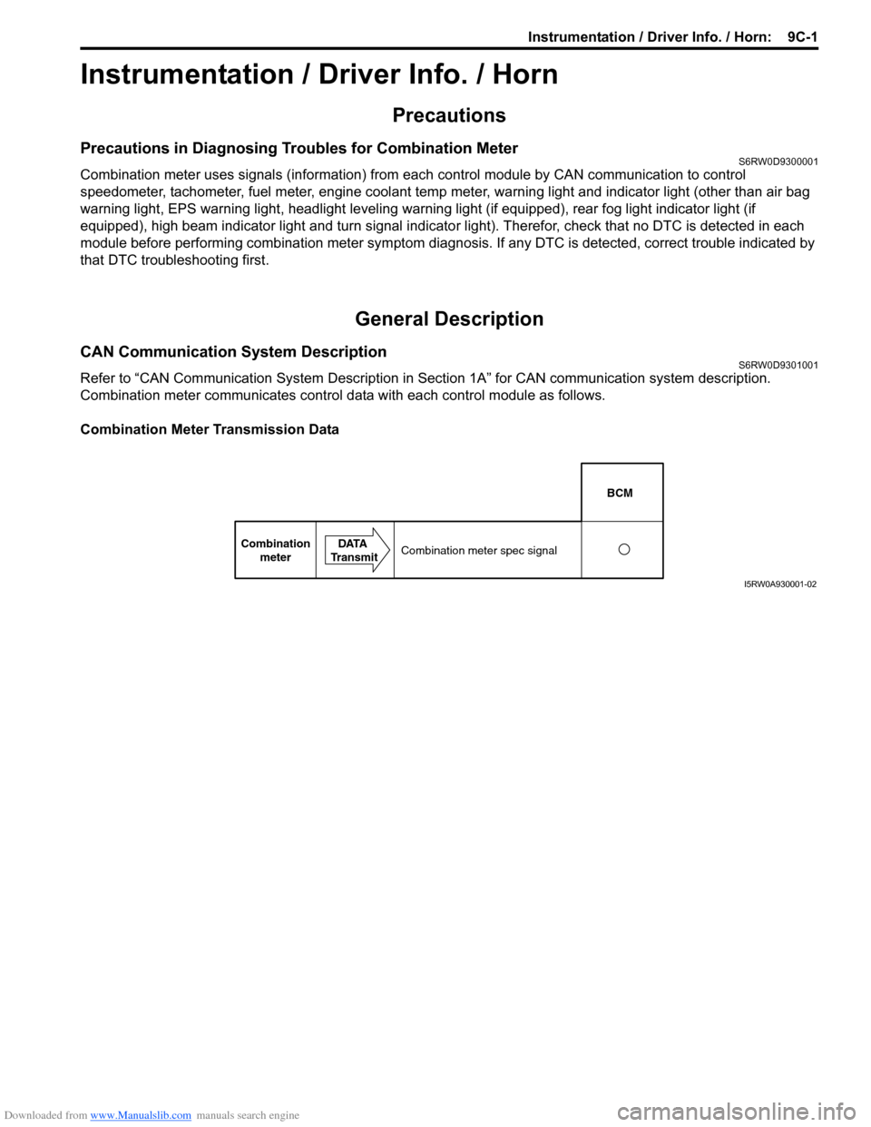
Refer to “CAN Communication System Description in Section 1A” for CAN communication system description.
Combination meter communicates control data with each control module as follows.
Combination Meter Transmission Data
BCM
Combination
meterDATA
TransmitCombination meter spec signal
I5RW0A930001-02
Page 1356 of 1556

Downloaded from www.Manualslib.com manuals search engine 9C-4 Instrumentation / Driver Info. / Horn:
Schematic and Routing Diagram
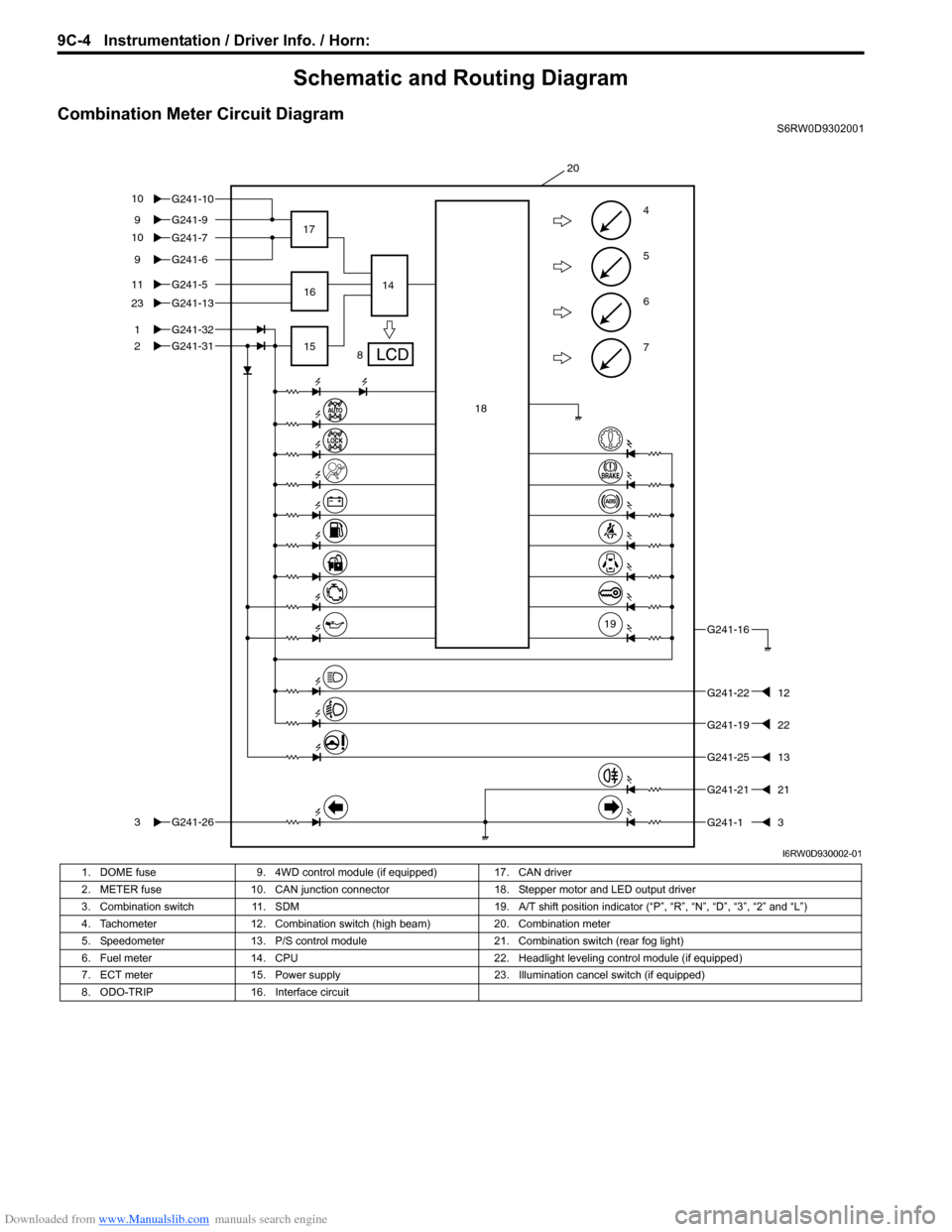
Combination Meter Circuit DiagramS6RW0D9302001
7
6
5
4G241-99
G241-5
1
2
11
G241-1323
G241-31
G241-263
G241-16
G241-2212
G241-2513
G241-13
8 17
1514
20
G241-32
G241-69
16
18
19
G241-2121
G241-7 G241-10 10
10
G241-1922
I6RW0D930002-01
1. DOME fuse 9. 4WD control module (if equipped) 17. CAN driver
2. METER fuse 10. CAN junction connector 18. Stepper motor and LED output driver
3. Combination switch 11. SDM 19. A/T shift position indicator (“P”, “R”, “N”, “D”, “3”, “2” and “L”)
4. Tachometer 12. Combination switch (high beam) 20. Combination meter
5. Speedometer 13. P/S control module 21. Combination switch (rear fog light)
6. Fuel meter 14. CPU 22. Headlight leveling control module (if equipped)
7. ECT meter 15. Power supply 23. Illumination cancel switch (if equipped)
8. ODO-TRIP 16. Interface circuit