2006 SUZUKI SX4 Rear View
[x] Cancel search: Rear ViewPage 437 of 1556

Downloaded from www.Manualslib.com manuals search engine Suspension General Diagnosis: 2A-3
Specifications
Wheel Alignment SpecificationsS6RW0D2107001
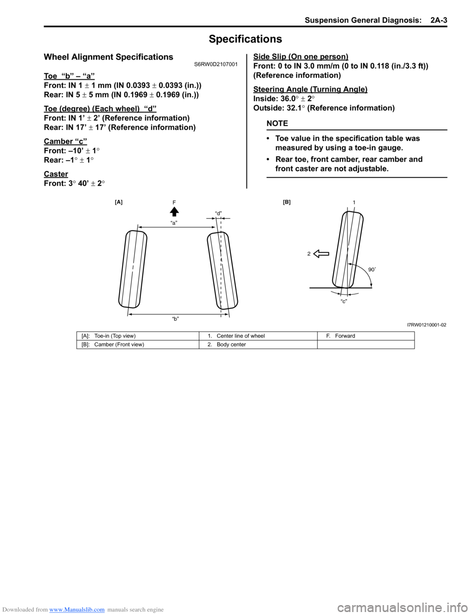
To e “b” – “a”
Front: IN 1 ± 1 mm (IN 0.0393 ± 0.0393 (in.))
Rear: IN 5 ± 5 mm (IN 0.1969 ± 0.1969 (in.))
Toe (degree) (Each wheel)
“d”
Front: IN 1’ ± 2’ (Reference information)
Rear: IN 17’ ± 17’ (Reference information)
Camber
“c”
Front: –10’ ± 1°
Rear: –1° ± 1°
Caster
Front: 3° 40’ ± 2°Side Slip (On one person)
Front: 0 to IN 3.0 mm/m (0 to IN 0.118 (in./3.3 ft))
(Reference information)
Steering Angle (Turning Angle)
Inside: 36.0° ± 2°
Outside: 32.1° (Reference information)
NOTE
• Toe value in the specification table was
measured by using a toe-in gauge.
• Rear toe, front camber, rear camber and
front caster are not adjustable.
“a”“d”
“b”F [A]
21
90�
“c” [B]
I7RW01210001-02
[A]: Toe-in (Top view) 1. Center line of wheel F. Forward
[B]: Camber (Front view) 2. Body center
Page 611 of 1556

Downloaded from www.Manualslib.com manuals search engine ABS: 4E-6
17+BB
18BLU
WHT12VGRN/ORN 34
30E08-9
RED
WHT 1226
WHT/RED
12V
E08-7
19GRN
GRN
E08-16
12V
5
76
21REDRED/BLK
12V
BLKWHTE08-22 E08-11
23BLKWHTLT GRN/BLKLT GRN
12V
E08-10 E08-21
E08-23
E08-26
E08-1E08-12
24BLKWHT
12V
YELBRNE08-19 E08-20
27
1 2
RED/BLK
WHTRED
WHTRED
WHTRED9
E08-2E08-13WHT
E08-6
RED
9
9
11
9
9
9
REDWHT
WHTRED
12VE08-25
M
BLK
BLK
WHT/BLUWHT/RED
WHT/BLUE08-24
WHT
E08 [A]
1
2
3
4
5
6
7 12
13
14
15
16
17
18
19
20
21
228
9
10
11
23
24
25
26
GRN/WHT
22
12V
BLKWHTWHTWHT/BLKE08-17 E08-18
GRN/ORN28
2033
31
29
25
15
32
GRN/YELE08-3GRN/BLK
8
12V
12V
13
14RED/BLK
RED/BLU
WHTRED6
16
10
BLK [B]
I6RW0D450001-02
[A]: Junction block with BCM 10. G sensor (4WD model) 22. Right-front wheel speed sensor
[B]: Junction block without BCM 11. 4WD control module 23. Left-rear wheel speed sensor
[C]: Terminal arrangement of ABS control module
connector (viewed from terminal side)12. BCM 24. Right-rear wheel speed sensor
1. Battery 13. Brake fluid level switch 25. ABS hydraulic unit / control module assembly
2. Main fuse box 14. Parking brake switch 26. Brake light switch
3. Ignition switch 15. CAN junction connector 27. Brake light
4. Junction block assembly 16. Keyless start control module 28. To ECM and shift lock relay (A/T model)
5. Combination meter 17. Data link connector (DLC) 29. Pump motor driver (transistor)
6. ABS warning light 18. To BCM, 4WD control module, P/S control
module, HVAC control module (auto A/C
model) and SDM30. Pump motor
7. EBD warning light (brake warning light)19. ECM 31. Solenoid valve power supply driver
8. Light driver module 20. TCM (A/T model) 32. Solenoid valve
9. CAN driver 21. Left-front wheel speed sensor 33. Solenoid valve driver (transistor)
Page 628 of 1556

Downloaded from www.Manualslib.com manuals search engine 4E-23 ABS:
DTC C1021 / C1022 / C1025 / C1026 / C1031 / C1032 / C1035 / C1036: Wheel Speed Sensor Circuit /
Sensor or Encoder
S6RW0D4504015
DTC C1021 / C1025 / C1031 / C1035: Right-Front / Left-Front / Right-Rear / Left-Rear Wheel Speed
Sensor Circuit
DTC C1022 / C1026 / C1032 / C1036: Right-Front / Left-Front / Right-Rear / Left-Rear Wheel Speed
Sensor or Encoder
Wiring Diagram
DTC Detecting Condition and Trouble Area
NOTE
When the vehicle was operated in any of the following ways, one of these DTCs may be set even when
the sensor is in good condition. If such possibility is suspected, clear DTC once referring to “DTC
Clearance” and after performing the driving test as described in Step 2 of “ABS Check”, check
whether or not any abnormality exists.
• The vehicle was driven with parking brake pulled.
• Wheel spin occurred while driving.
• Wheel(s) was turned while the vehicle was jacked up.
• The vehicle was stuck.
E08 [A]
1
2
3
4
5
6
7 12
13
14
15
16
17
18
19
20
21
228
9
10
11
23
24
25
26
WHTGRNGRN/ORN
3
4
E08-9
9
12V
8
7
6
5
BLKWHT
BLKWHT
REDRED/BLK
LT GRN/BLKLT GRN
E08-22 E08-11
E08-10 E08-21
E08-23BLK
12V
12V
12V
12V
BLKWHT
BLKWHTWHTWHT/BLK
E08-17 E08-18
YELBRN
E08-19 E08-20
12
I7RW01450007-03
[A]: ABS control module connector (viewed from terminal
side)4. Junction block assembly 8. Right-rear wheel speed sensor
1. Battery 5. Left-front wheel speed sensor 9. ABS hydraulic unit / control module assembly
2. Main fuse box 6. Right- front wheel speed sensor
3. Ignition switch 7. Left-rear wheel speed sensor
DTC Detecting Condition Trouble Area
C1021, C1025, C1031, C1035:
Wheel speed sensor circuit is opened, shorted to power,
ground and/or each other circuit.
C1022, C1026, C1032, C1036:
• Wheel speed is different from other wheel speed
(vehicle speed) for more than specified time.
• Abnormal wheel speed sensor signal is detected for
more than specified time.• Wheel speed sensor
• Wheel speed sensor circuit
• Wheel encoder
• ABS control module
Page 631 of 1556

Downloaded from www.Manualslib.com manuals search engine ABS: 4E-26
DTC C1041 / C1042 / C1045 / C1046 / C1051 / C1052 / C1055 / C1056: Inlet / Outlet SolenoidS6RW0D4504017
DTC C1041 / C1045 / C1051 / C1055: Right-Front / Left-Front / Right-Rear / Left- Rear Inlet Solenoid
DTC C1042 / C1046 / C1052 / C1056: Right-Front / Left-Front / Right-Rear / Left- Rear Outlet Solenoid
Wiring Diagram
DTC Detecting Condition and Trouble Area
DTC Troubleshooting
WHT/BLU
1 2
5
3
BLK
E08-24
E08-23
6 4
E08 [A]
1
2
3
4
5
6
7 12
13
14
15
16
17
18
19
20
21
228
9
10
11
23
24
25
26
I7RW01450008-02
[A]: ABS control module assembly connector (viewed from terminal side) 4. ABS hydraulic unit / control module assembly
1. Battery5. Solenoid valve power supply driver (transistor)
2. Main fuse box6. Solenoid valve driver
3. Solenoid valve
DTC Detecting Condition Trouble Area
DTC C1041, C1042, C1045, C1046, C1051, C1052,
C1055, C1056:
• Solenoid valve circuit is opened, shorted to power,
ground and/or each valve in ABS hydraulic unit / control
module assembly.
• Mismatching solenoid output and solenoid monitor is
detected.• ABS control module
Step Action Yes No
1Was “ABS Check” performed?Go to Step 2. Go to “ABS Check”.
2ABS hydraulic unit / control module power source
circuit check
1) Turn ignition switch to OFF position.
2) Disconnect ABS hydraulic unit / control module
connector.
3) Check for proper connection to ABS hydraulic unit /
control module connector at terminal “E08-24” and “E08-
23”.
4) If OK, then measure voltage between terminal “E08-24”
of module connector and “E08-23”.
Is it 10 – 14 V?Substitute a known-
good ABS hydraulic unit
/ control module
assembly and recheck.“WHT/BLU” or “BLK”
circuit open or high
resistance.
Page 947 of 1556

Downloaded from www.Manualslib.com manuals search engine Air Conditioning System: Manual Type 7B-7
Electronic Control System Components LocationS6RW0D7213002
NOTE
The figure shows left-hand steering vehicle. For right-hand steering vehicle, parts with (*) are installed
at the opposite side.
[A]
8*
9* 10*
11
1
5
7*
6
7*
12
13
14
1715
1642
3
I6RW0C721003-01
[A]: Junction block assembly viewed from relay side 6. Blower motor relay 12. Air intake selector
1. A/C refrigerant pressure sensor 7. Junction block assembly 13. Rear defogger switch
2. Compressor relay 8. Air intake actuator 14. Temperature selector
3. Condenser cooling fan relay 9. Blower motor 15. Blower speed selector
4. ECT sensor 10. Blower motor resistor 16. Air flow selector
5. Condenser cooling fan 11. HVAC control unit 17. A/C switch
Page 984 of 1556

Downloaded from www.Manualslib.com manuals search engine 7B-44 Air Conditioning System: Automatic Type
Electronic Control System Components LocationS6RW0D7223002
NOTE
The figure shows left-hand steering vehicle. For right-hand steering vehicle, parts with (*) are installed
at the opposite side.
[A]
2
3
5
1
4
78*
18
19
20
23
22 219*
10*
11*
12*
13*
15* 16* 17
14*
8*6
I6RW0C722003-01
[A]: Junction block assembly viewed from relay
side8. Junction block assembly 16. Blower motor controller
1. A/C refrigerant pressure sensor 9. Sunload sensor 17. HVAC control module
2. Compressor relay 10. Inside air temperature sensor 18. Temperature selector
3. Condenser cooling fan relay 11. Air flow control actuator 19. Blower speed selector
4. Outside air temperature sensor 12. Temperature control actuator 20. MODE (air flow) selector
5. ECT sensor 13. Evaporator temperature sensor 21. A/C switch
6. Condenser cooling fan 14. Air intake actuator 22. Air intake selector
7. Blower motor relay 15. Blower motor 23. Rear defogger switch
Page 1016 of 1556

Downloaded from www.Manualslib.com manuals search engine 7B-76 Air Conditioning System: Automatic Type
Inspection of HVAC Control Module and Its CircuitS6RW0D7224029
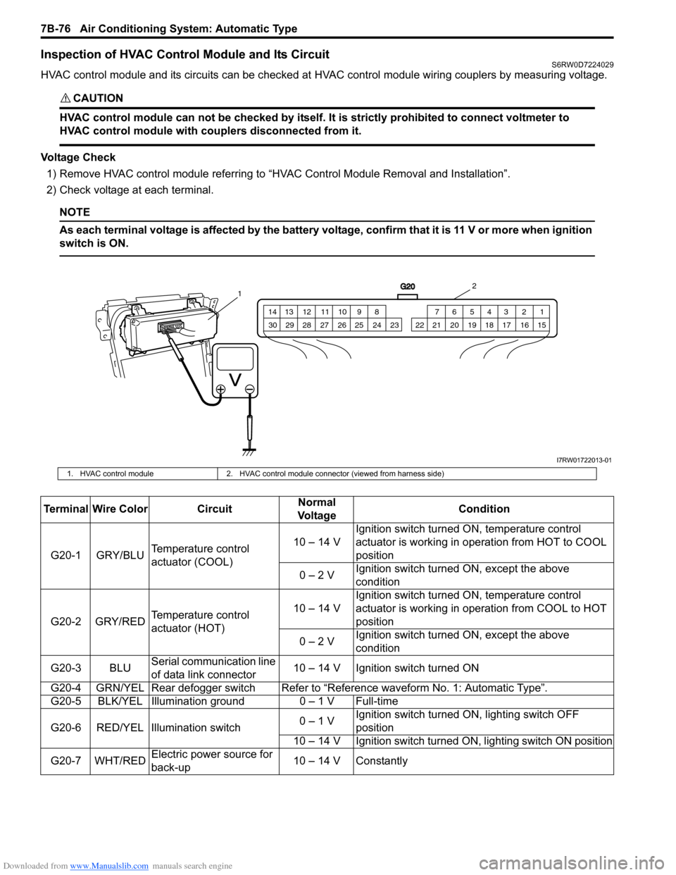
HVAC control module and its circuits can be checked at HVAC control module wiring couplers by measuring voltage.
CAUTION!
HVAC control module can not be checked by itself. It is strictly prohibited to connect voltmeter to
HVAC control module with couplers disconnected from it.
Voltage Check
1) Remove HVAC control module referring to “HVAC Control Module Removal and Installation”.
2) Check voltage at each terminal.
NOTE
As each terminal voltage is affected by the battery voltage, confirm that it is 11 V or more when ignition
switch is ON.
G20
1 2 3 4 5 6 7 8 9 10 11 12 13 14
15 16 17 18 19 20 21 24 23 22 25 26 27 28 29 30
12
I7RW01722013-01
1. HVAC control module 2. HVAC control module connector (viewed from harness side)
Terminal Wire Color CircuitNormal
Vo l ta g eCondition
G20-1 GRY/BLUTemperature control
actuator (COOL)10 – 14 VIgnition switch turned ON, temperature control
actuator is working in operation from HOT to COOL
position
0 – 2 VIgnition switch turned ON, except the above
condition
G20-2 GRY/REDTemperature control
actuator (HOT)10 – 14 VIgnition switch turned ON, temperature control
actuator is working in operation from COOL to HOT
position
0 – 2 VIgnition switch turned ON, except the above
condition
G20-3 BLUSerial communication line
of data link connector10 – 14 V Ignition switch turned ON
G20-4 GRN/YEL Rear defogger switchRefer to “Reference waveform No. 1: Automatic Type”.
G20-5 BLK/YEL Illumination ground 0 – 1 V Full-time
G20-6 RED/YEL Illumination switch0 – 1 VIgnition switch turned ON, lighting switch OFF
position
10 – 14 V Ignition switch turned ON, lighting switch ON position
G20-7 WHT/REDElectric power source for
back-up10 – 14 V Constantly
Page 1161 of 1556

Downloaded from www.Manualslib.com manuals search engine Table of Contents 9- i
9
Section 9
CONTENTS
Body, Cab and Accessories
Precautions ................................................. 9-1
Precautions............................................................. 9-1
Precautions on Body, Cab and Accessories ......... 9-1
Precautions for Body Service ................................ 9-1
Fastener Caution for Body Service ....................... 9-1
Wiring Systems........................................ 9A-1
Precautions........................................................... 9A-1
Cautions in Body Electrical System Servicing..... 9A-1
General Description ............................................. 9A-1
Abbreviations ...................................................... 9A-1
Wire / Connector Color Symbols ......................... 9A-1
Symbols and Marks ............................................ 9A-2
How to Read Connector Layout Diagram ........... 9A-4
How to Read Connector Codes and Terminal
Nos.................................................................... 9A-5
How to Read Ground Point ................................. 9A-8
How to Read Power Supply Diagram.................. 9A-9
How to Read System Circuit Diagram................. 9A-9
Connector Layout Diagram ............................... 9A-11
Connector Layout Diagram ............................... 9A-11
Engine Compartment ........................................ 9A-11
Instrument Panel ............................................... 9A-19
Door, Roof......................................................... 9A-25
Floor .................................................................. 9A-28
Rear .................................................................. 9A-32
Ground Point ...................................................... 9A-33
Ground (earth) Point ......................................... 9A-33
Power Supply Diagram ...................................... 9A-34
Power Supply Diagram ..................................... 9A-34
Fuses and the Protected Parts ......................... 9A-36
Fuses in Main Fuse Box ................................... 9A-36
Individual Circuit Fuse Box No. 1 ...................... 9A-37
Individual Circuit Fuse Box No. 2 (In J/B
(Except Taiwan)) ............................................. 9A-38
Individual Circuit Fuse Box No. 2 (In J/B
(Taiwan)) ......................................................... 9A-40
Junction Block (J/B) Connector / Fuse Layout .. 9A-42
Junction Block Inner Circuit (Overview
(Except Taiwan)) ............................................. 9A-43
Junction Block Inner Circuit (Detail (Except
Taiwan)) .......................................................... 9A-45
Junction Block Inner Circuit (Overview
(Taiwan)) ......................................................... 9A-50Junction Block Inner Circuit (Detail (Taiwan)) ... 9A-52
System Circuit Diagram.....................................9A-57
System Circuit Diagram .................................... 9A-57
A-1 Cranking System Circuit Diagram .............. 9A-58
A-2 Charging System Circuit Diagram .............. 9A-59
A-3 Ignition System Circuit Diagram (M15A
engine, M16A engine) ..................................... 9A-60
A-3 Ignition System Circuit Diagram (J20A
engine) ............................................................ 9A-61
A-4 Cooling System Circuit Diagram (M15A
engine, M16A engine) ..................................... 9A-62
A-4 Cooling System Circuit Diagram (J20A
engine) ............................................................ 9A-63
A-5 Engine and A/C Control System Circuit
Diagram (M15A engine) .................................. 9A-64
A-5 Engine and A/C Control System Circuit
Diagram (M16A engine) .................................. 9A-68
A-5 Engine and A/C Control System Circuit
Diagram (J20A engine) ................................... 9A-72
A-6 A/T Control System Circuit Diagram........... 9A-76
A-7 Immobilizer System Circuit Diagram .......... 9A-78
A-8 Body Control System Circuit Diagram
(Except Taiwan) .............................................. 9A-79
A-8 Body Control System Circuit Diagram
(Taiwan) .......................................................... 9A-83
A-10 4WD Control System (Except Taiwan) ..... 9A-87
B-1 Windshield Wiper and Washer Circuit
Diagram........................................................... 9A-88
B-2 Rear Wiper and Washer Circuit Diagram
(Except Taiwan) .............................................. 9A-89
B-2 Rear Wiper and Washer Circuit Diagram
(Taiwan) .......................................................... 9A-90
B-3 Rear Defogger Circuit Diagram (Except
Taiwan) ........................................................... 9A-91
B-3 Rear Defogger Circuit Diagram (Taiwan) ... 9A-92
B-4 Power Window Circuit Diagram .................. 9A-93
B-5 Power Door Lock Circuit Diagram (Except
Taiwan) ........................................................... 9A-95
B-5 Power Door Lock Circuit Diagram
(Taiwan) .......................................................... 9A-97
B-6 Power Mirror Circuit Diagram (Except
Taiwan) ........................................................... 9A-99
B-6 Power Mirror Circuit Diagram (Taiwan) .... 9A-100
B-7 Horn Circuit Diagram ................................ 9A-101
B-8 Seat Heater Circuit Diagram..................... 9A-102