Page 1479 of 1556
Downloaded from www.Manualslib.com manuals search engine Body Electrical Control System: 10B-6
Connector Layout Diagram of BCM and Junction BlockS6RW0DA202002
BCM and Junction Block Connectors (Viewed from Harness Side)
I6RW0CA20004-01
[A]: Junction block (viewed from BCM side) 2. Junction block 5. Rear wiper relay
[B]: Junction block (viewed from relay side) 3. Blower motor relay 6. Rear end door window defogger relay
1. BCM 4. Horn relay 7. Turn signal and hazard warning relay
Page 1529 of 1556

Downloaded from www.Manualslib.com manuals search engine Keyless Start System: 10E-7
Keyless Start Control Module Reception Data
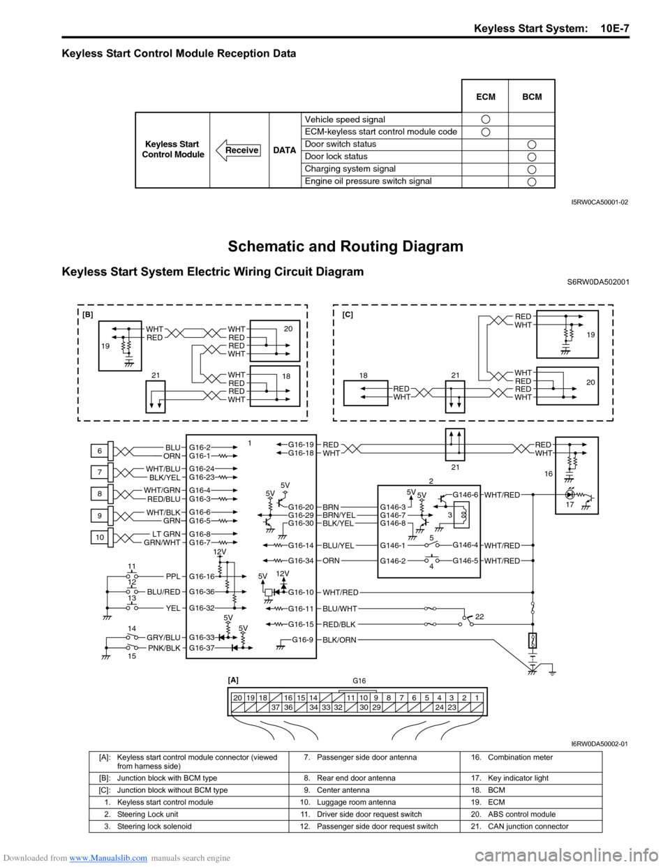
Schematic and Routing Diagram
Keyless Start System Electric Wiring Circuit DiagramS6RW0DA502001
Vehicle speed signal
ECM-keyless start control module code
Door switch status
Door lock status
Charging system signal
Engine oil pressure switch signalECM BCM
DATA
ReceiveKeyless Start
Control Module
I5RW0CA50001-02
BLK/ORNG16-9
G16-15
G16-14
G16-37G16-33
G16-16
G16-20G16-29G16-30
G16-36
G16-32
G16-10
G16-34
G16-11BLU/WHT
WHT/RED
WHT/RED
PNK/BLKGRY/BLU
BLU/RED
YEL
PPL
RED/BLK
5V5V 5V5V
5V5V
5V12V 12V
G16-2G16-1BLU
ORNWHTREDWHTREDG16-18G16-19
BLU/YEL
ORN
G16-24G16-23
BLK/YEL WHT/BLU
G16-7
GRN/WHTLT GRNG16-8
G16-5G16-6
GRN WHT/BLK
G16-4G16-3 WHT/GRN
RED/BLU
BLK/YELBRN/YELBRNG146-3
G146-1
G146-2G146-5
G146-4
G146-6
G146-7G146-8
WHT/RED
WHT/RED
G16[A]
1 2 3 4 5 6 7 8 9 10 11 14 15 16
36 34 33 32 30 29 24 23 37 18 19 20
WHTRED
WHT
WHT
RED
RED
WHTRED
6
7
8
9
10
11
12
13
14
15118
21
21
2
3
5
419
20
16
17
22
WHTRED
WHTREDWHTRED
18 1920WHTRED
WHTRED
21
[B][C]
I6RW0DA50002-01
[A]: Keyless start control module connector (viewed
from harness side)7. Passenger side door antenna 16. Combination meter
[B]: Junction block with BCM type 8. Rear end door antenna 17. Key indicator light
[C]: Junction block without BCM type 9. Center antenna 18. BCM
1. Keyless start control module 10. Luggage room antenna 19. ECM
2. Steering Lock unit 11. Driver side door request switch 20. ABS control module
3. Steering lock solenoid 12. Passenger side door request switch 21. CAN junction connector
Page 1537 of 1556

Downloaded from www.Manualslib.com manuals search engine Keyless Start System: 10E-15
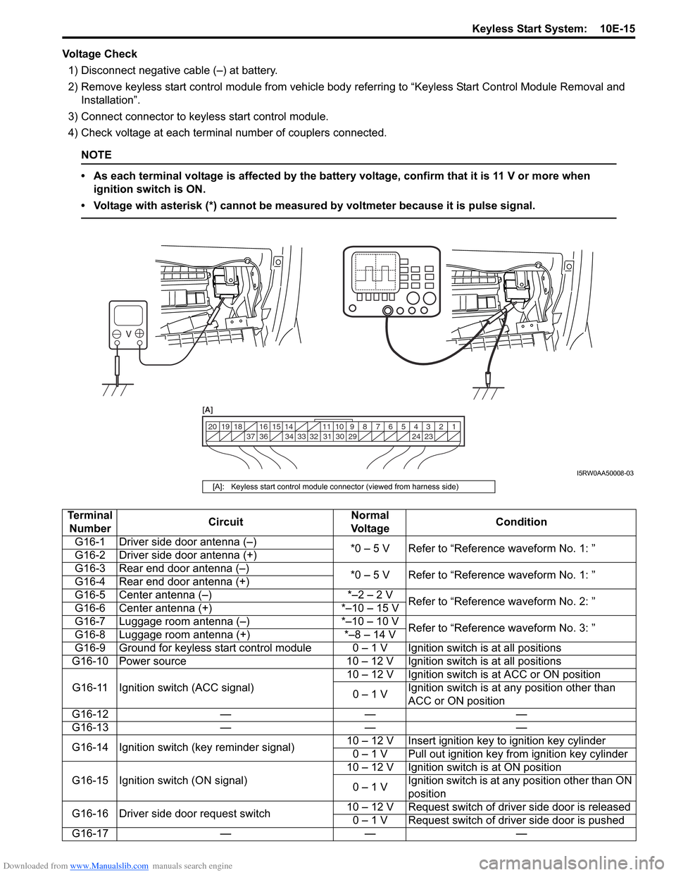
Voltage Check
1) Disconnect negative cable (–) at battery.
2) Remove keyless start control module from vehicle body referring to “Keyless Start Control Module Removal and
Installation”.
3) Connect connector to keyless start control module.
4) Check voltage at each terminal number of couplers connected.
NOTE
• As each terminal voltage is affected by the battery voltage, confirm that it is 11 V or more when
ignition switch is ON.
• Voltage with asterisk (*) cannot be measured by voltmeter because it is pulse signal.
1 2 3 4 5 6 7 8 9 10 11 14 15 16
36 34 33 32 31 30 29 24 23 37 18 19 20
[A]
I5RW0AA50008-03
[A]: Keyless start control module connector (viewed from harness side)
Terminal
NumberCircuitNormal
Vo l ta g eCondition
G16-1 Driver side door antenna (–)
*0 – 5 V Refer to “Reference waveform No. 1: ”
G16-2 Driver side door antenna (+)
G16-3 Rear end door antenna (–)
*0 – 5 V Refer to “Reference waveform No. 1: ”
G16-4 Rear end door antenna (+)
G16-5 Center antenna (–) *–2 – 2 V
Refer to “Reference waveform No. 2: ”
G16-6 Center antenna (+) *–10 – 15 V
G16-7 Luggage room antenna (–) *–10 – 10 V
Refer to “Reference waveform No. 3: ”
G16-8 Luggage room antenna (+) *–8 – 14 V
G16-9 Ground for keyless start control module 0 – 1 V Ignition switch is at all positions
G16-10 Power source 10 – 12 V Ignition switch is at all positions
G16-11 Ignition switch (ACC signal)10 – 12 V Ignition switch is at ACC or ON position
0 – 1 VIgnition switch is at any position other than
ACC or ON position
G16-12 — — —
G16-13 — — —
G16-14 Ignition switch (key reminder signal)10 – 12 V Insert ignition key to ignition key cylinder
0 – 1 V Pull out ignition key from ignition key cylinder
G16-15 Ignition switch (ON signal)10 – 12 V Ignition switch is at ON position
0 – 1 VIgnition switch is at any position other than ON
position
G16-16 Driver side door request switch10 – 12 V Request switch of driver side door is released
0 – 1 V Request switch of driver side door is pushed
G16-17 — — —
Page 1542 of 1556

Downloaded from www.Manualslib.com manuals search engine 10E-20 Keyless Start System:
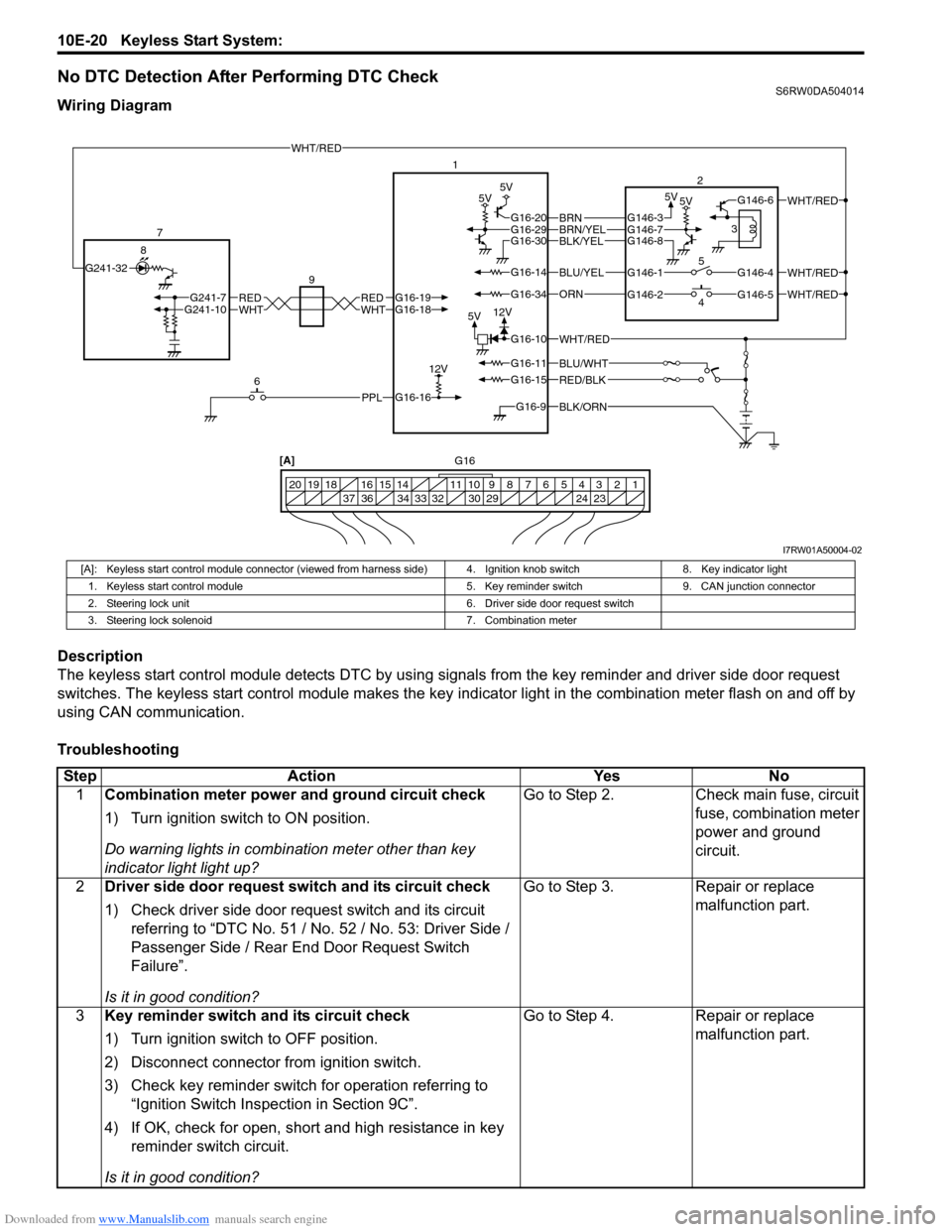
No DTC Detection After Performing DTC CheckS6RW0DA504014
Wiring Diagram
Description
The keyless start control module detects DTC by using signals from the key reminder and driver side door request
switches. The keyless start control module makes the key indicator light in the combination meter flash on and off by
using CAN communication.
Troubleshooting
BLK/ORNG16-9
G16-15
G16-14
G16-16
G16-20G16-29G16-30
G16-10
G16-34
G16-11BLU/WHT
WHT/RED
WHT/RED
WHT/RED
PPL
RED/BLK
5V5V 5V5V
5V12V
12VWHTREDWHTREDG16-18G16-19G241-10G241-7
BLU/YEL
ORN
BLK/YELBRN/YELBRNG146-3
G146-1
G146-2G146-5
G146-4
G146-6
G146-7G146-8
WHT/RED
WHT/RED
G241-32
6 7
81
2
4 53
20 12 3 4 5 6 7 8 9 10 11 14 15 16
36 34 33 32 30 29 24 23 37 18 19
[A]
9
G16
I7RW01A50004-02
[A]: Keyless start control module connector (viewed from harness side) 4. Ignition knob switch 8. Key indicator light
1. Keyless start control module 5. Key reminder switch 9. CAN junction connector
2. Steering lock unit 6. Driver side door request switch
3. Steering lock solenoid 7. Combination meter
Step Action Yes No
1Combination meter power and ground circuit check
1) Turn ignition switch to ON position.
Do warning lights in combination meter other than key
indicator light light up?Go to Step 2. Check main fuse, circuit
fuse, combination meter
power and ground
circuit.
2Driver side door request switch and its circuit check
1) Check driver side door request switch and its circuit
referring to “DTC No. 51 / No. 52 / No. 53: Driver Side /
Passenger Side / Rear End Door Request Switch
Failure”.
Is it in good condition?Go to Step 3. Repair or replace
malfunction part.
3Key reminder switch and its circuit check
1) Turn ignition switch to OFF position.
2) Disconnect connector from ignition switch.
3) Check key reminder switch for operation referring to
“Ignition Switch Inspection in Section 9C”.
4) If OK, check for open, short and high resistance in key
reminder switch circuit.
Is it in good condition?Go to Step 4. Repair or replace
malfunction part.
Page 1548 of 1556

Downloaded from www.Manualslib.com manuals search engine 10E-26 Keyless Start System:
DTC No. 31: Lost Communication with BCMS6RW0DA504020
Refer to “Troubleshooting for CAN-DTC in Section 1A”.
DTC No. 33: Control Module Communication Bus OffS6RW0DA504021
Refer to “Troubleshooting for CAN-DTC in Section 1A”.
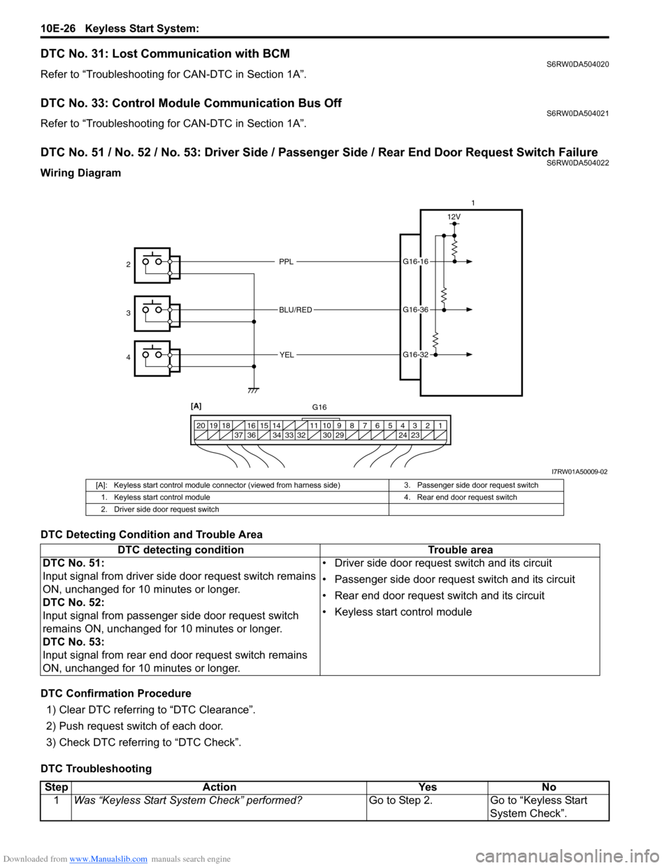
DTC No. 51 / No. 52 / No. 53: Driver Side / Passenger Side / Rear End Door Request Switch FailureS6RW0DA504022
Wiring Diagram
DTC Detecting Condition and Trouble Area
DTC Confirmation Procedure
1) Clear DTC referring to “DTC Clearance”.
2) Push request switch of each door.
3) Check DTC referring to “DTC Check”.
DTC Troubleshooting
PPL
BLU/RED
YELG16-16
G16-36
G16-32
12V
1 2 3 4 5 6 7 8 9 10 11 14 15 16
36 34 33 32 30 29 24 23 37 18 19 20
1
2
3
4
[A]
G16
I7RW01A50009-02
[A]: Keyless start control module connector (viewed from harness side) 3. Passenger side door request switch
1. Keyless start control module 4. Rear end door request switch
2. Driver side door request switch
DTC detecting condition Trouble area
DTC No. 51:
Input signal from driver side door request switch remains
ON, unchanged for 10 minutes or longer.
DTC No. 52:
Input signal from passenger side door request switch
remains ON, unchanged for 10 minutes or longer.
DTC No. 53:
Input signal from rear end door request switch remains
ON, unchanged for 10 minutes or longer.• Driver side door request switch and its circuit
• Passenger side door request switch and its circuit
• Rear end door request switch and its circuit
• Keyless start control module
Step Action Yes No
1Was “Keyless Start System Check” performed?Go to Step 2. Go to “Keyless Start
System Check”.
Page:
< prev 1-8 9-16 17-24