2006 SUZUKI SX4 seat memory
[x] Cancel search: seat memoryPage 76 of 1556

Downloaded from www.Manualslib.com manuals search engine 1A-26 Engine General Information and Diagnosis:
• The MIL is turned on when the ECM and/or
TCM detect malfunction(s). Each ECM and
TCM stores diagnostic information as the
diagnostic trouble code (DTC) in its
memory and outputs the DTC to the scan
tool.
Therefore, check both of the ECM and TCM
for any DTC with the scan tool because the
DTC stored in ECM and TCM is not read
and displayed at a time. However, each of
the ECM and TCM needs not to be checked
with the generic scan tool because the
DTC stored in ECM and TCM is read and
displayed at a time.
1) Prepare CAN communication OBD generic scan tool
or SUZUKI scan tool.
Special tool
(A): SUZUKI scan tool (SUZUKI-SDT)
2) With ignition switch OFF, connect it to DLC (1)
located on underside of instrument panel at driver’s
seat side.
3) Turn ignition switch ON and confirm that MIL lights.
4) Read DTC and freeze frame data according to
instructions displayed on scan tool and print them or
write them down. Refer to scan tool operator’s
manual for details.
If communication between scan tool and ECM is not
possible, go to “Troubleshooting for Communication
Error with Scan Tool Using CAN”.
5) After completing the check, turn ignition switch off
and disconnect scan tool from DLC.
DTC ClearanceS6RW0D1104004
NOTE
There are two types of OBD system
depending on the vehicle specification.
For identification, refer to “Precaution on On-
Board Diagnostic (OBD) System”.
1) Connect SUZUKI scan tool or CAN communication
OBD generic scan tool to data link connector in the
same manner as when making this connection for
DTC check.2) Turn ignition switch OFF and then ON.
3) Erase DTC and pending DTC according to
instructions displayed on scan tool. Freeze frame
data is cleared with the DTC. Refer to scan tool
operator’s manual for further details.
If communication between scan tool and ECM is not
possible, go to “Troubleshooting for Communication
Error with Scan Tool Using CAN”.
4) After completing the clearance, turn ignition switch
OFF and disconnect scan tool from data link
connector.
NOTE
DTC and freeze frame data stored in ECM
memory are also cleared in the following
cases. Be careful not to clear them before
keeping their record.
• When power to ECM is cut off (by
disconnecting battery cable, removing
fuse or disconnecting ECM connectors).
• When the same malfunction (DTC) is not
detected again during 40 engine warm-up
cycles. (See “Warm-Up Cycle” of “On-
Board Diagnostic System Description”.)
Troubleshooting for Communication Error with
Scan Tool Using CAN
S6RW0D1104083
Perform this troubleshooting when it is not possible to
communicate between scan tool and ECM/TCM.
NOTE
• When performing this troubleshooting, be
sure to have full understanding of
“Precaution on CAN Troubleshooting” and
observe it.
• It may be possible that CAN system has
trouble because of fuse blown or low
battery voltage. Before troubleshooting,
check to make sure that fuse, battery
voltage and generator status are normal.
• When disconnecting each control module
connector in this troubleshooting, various
DTCs will be detected. Be sure to clear
DTCs in the following control modules
after completing this troubleshooting.
–ECM
–BCM
–TCM
– Keyless start control module
– 4WD control module
– HVAC control module (Auto A/C model)
– P/S control module
(A) 1I5RW0C110011-01
Page 1474 of 1556

Downloaded from www.Manualslib.com manuals search engine 10B-1 Body Electrical Control System:
Control Systems
Body Electrical Control System
Precautions
Precautions in Diagnosing TroubleS6RW0DA200001
• Diagnostic information stored in BCM memory can be cleared as well as checked by using SUZUKI scan tool.
Before using scan tool, read its Operator’s (Instruction) Manual carefully to have good understanding as to what
functions are available and how to use it.
• Be sure to read “Precautions for Electrical Circuit Service in Section 00” before inspection and observe what is
written there.
• Communication of ECM, TCM (A/T model), ABS control module, 4WD control module (if equipped), keyless start
control module (if equipped), combination meter and BCM is established by CAN (Controller Area Network). For
detail of CAN communication for BCM, refer to “CAN Communication System Description”. Therefore, handle CAN
communication line with care referring to “Precaution for CAN Communication System in Section 00”.
General Description
BCM General DescriptionS6RW0DA201001
The Body electrical Control Module (BCM) is
incorporated in junction block. Do not attempt removal of
BCM from junction block as it may cause contact failure.
The BCM incorporates relays and controllers which are
used for the following systems and controls them.
• Power door lock (if equipped)
• Keyless entry (if equipped)
• Door lock function of keyless start system (if
equipped)
• Rear wiper
• Combination meter
• Interior light• Warning buzzer
• Rear end door window defogger and door mirror
heater (if equipped)
• Rear end door opener (if equipped)
• Theft deterrent light
Also, the BCM has a function to cause the interior light
and open door warning light in the combination meter to
turn off when any door is left open for longer than 15
minutes to reduce wasteful battery consumption.
In addition, it is possible to check operation of actuator
which is controlled by BCM by using the output test
function of SUZUKI scan tool to operate actuator
simulatively.
CAN Communication System DescriptionS6RW0DA201002
Refer to “CAN Communication System Description in Section 1A” for CAN communication system description.
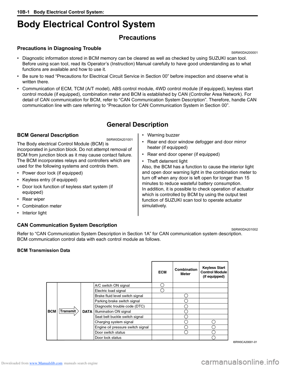
BCM communication control data with each control module as follows.
BCM Transmission Data
A/C switch ON signal
Electric load signal
Brake fluid level switch signal
Parking brake switch signal
Diagnostic trouble code (DTC)
Illumination ON signal
Seat belt buckle switch signal
Charging system signal
Engine oil pressure switch signal
Door switch status
Door lock statusECMKeyless Start
Control Module
(if equipped) Combination
Meter
BCMTransmit
DATA
I6RW0CA20001-01
Page 1481 of 1556

Downloaded from www.Manualslib.com manuals search engine Body Electrical Control System: 10B-8
Diagnostic Information and Procedures
BCM Self-Diagnosis FunctionS6RW0DA204001
• BCM monitors conditions of the system components and its circuit with ignition switch turned to ON position. When
an abnormality in the system occurs, the area where that abnormality lies is stored in the memory of EEPROM in
BCM.
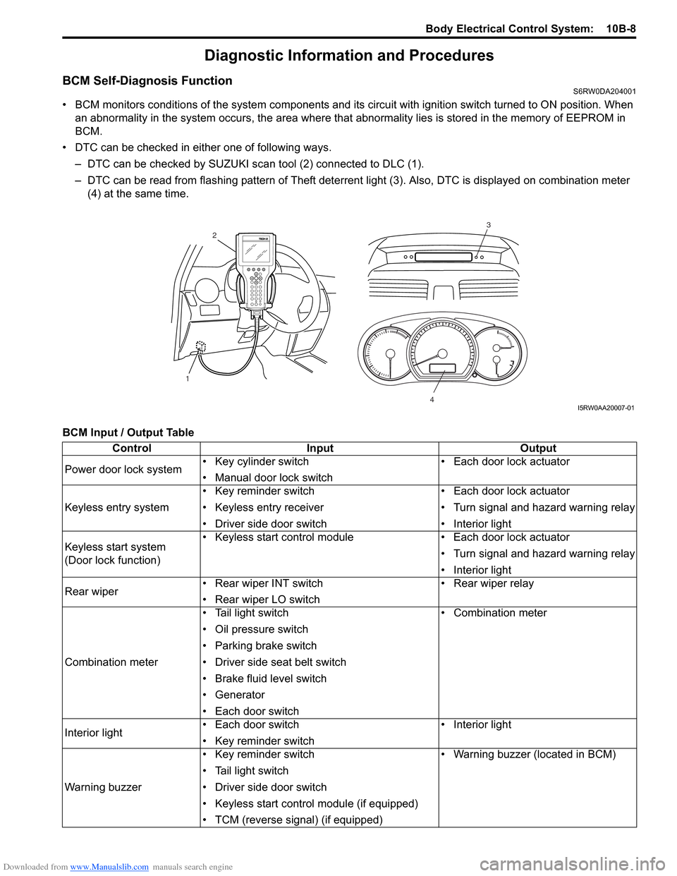
• DTC can be checked in either one of following ways.
– DTC can be checked by SUZUKI scan tool (2) connected to DLC (1).
– DTC can be read from flashing pattern of Theft deterrent light (3). Also, DTC is displayed on combination meter
(4) at the same time.
BCM Input / Output Table
3
4
2
1
I5RW0AA20007-01
Control Input Output
Power door lock system• Key cylinder switch
• Manual door lock switch• Each door lock actuator
Keyless entry system• Key reminder switch
• Keyless entry receiver
• Driver side door switch• Each door lock actuator
• Turn signal and hazard warning relay
• Interior light
Keyless start system
(Door lock function)• Keyless start control module • Each door lock actuator
• Turn signal and hazard warning relay
• Interior light
Rear wiper • Rear wiper INT switch
• Rear wiper LO switch• Rear wiper relay
Combination meter• Tail light switch
• Oil pressure switch
• Parking brake switch
• Driver side seat belt switch
• Brake fluid level switch
• Generator
• Each door switch• Combination meter
Interior light• Each door switch
• Key reminder switch• Interior light
Warning buzzer• Key reminder switch
• Tail light switch
• Driver side door switch
• Keyless start control module (if equipped)
• TCM (reverse signal) (if equipped)• Warning buzzer (located in BCM)