Page 2245 of 2896
HEADLAMP (FOR CANADA) - DAYTIME LIGHT SYSTEM -
LT-37
C
D
E
F
G
H
I
J
L
MA
B
LT
Revision: June 20062007 Versa
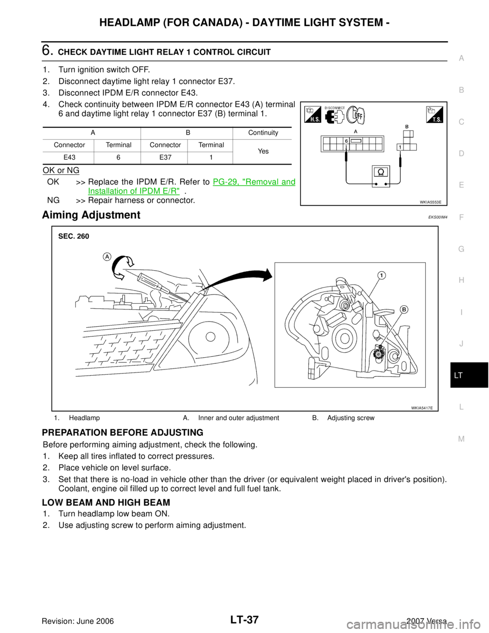
6. CHECK DAYTIME LIGHT RELAY 1 CONTROL CIRCUIT
1. Turn ignition switch OFF.
2. Disconnect daytime light relay 1 connector E37.
3. Disconnect IPDM E/R connector E43.
4. Check continuity between IPDM E/R connector E43 (A) terminal
6 and daytime light relay 1 connector E37 (B) terminal 1.
OK or NG
OK >> Replace the IPDM E/R. Refer to PG-29, "Removal and
Installation of IPDM E/R" .
NG >> Repair harness or connector.
Aiming AdjustmentEKS00IM4
PREPARATION BEFORE ADJUSTING
Before performing aiming adjustment, check the following.
1. Keep all tires inflated to correct pressures.
2. Place vehicle on level surface.
3. Set that there is no-load in vehicle other than the driver (or equivalent weight placed in driver's position).
Coolant, engine oil filled up to correct level and full fuel tank.
LOW BEAM AND HIGH BEAM
1. Turn headlamp low beam ON.
2. Use adjusting screw to perform aiming adjustment.
A B Continuity
Connector Terminal Connector Terminal
Ye s
E43 6 E37 1
WKIA5553E
1. Headlamp A. Inner and outer adjustment B. Adjusting screw
WKIA5417E
Page 2249 of 2896
FRONT FOG LAMP
LT-41
C
D
E
F
G
H
I
J
L
MA
B
LT
Revision: June 20062007 Versa
FRONT FOG LAMPPFP:26150
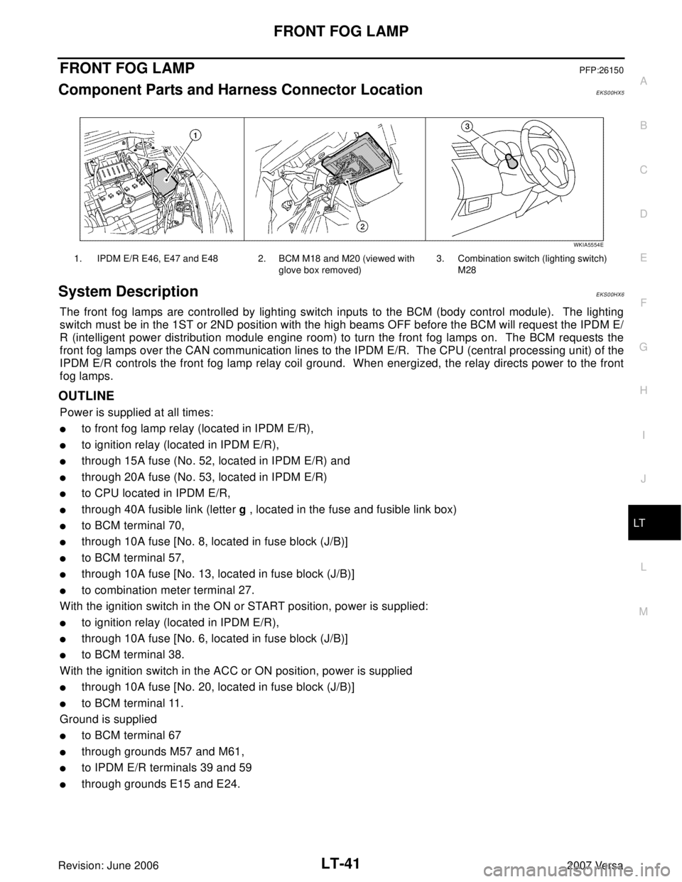
Component Parts and Harness Connector LocationEKS00HX5
System DescriptionEKS00HX6
The front fog lamps are controlled by lighting switch inputs to the BCM (body control module). The lighting
switch must be in the 1ST or 2ND position with the high beams OFF before the BCM will request the IPDM E/
R (intelligent power distribution module engine room) to turn the front fog lamps on. The BCM requests the
front fog lamps over the CAN communication lines to the IPDM E/R. The CPU (central processing unit) of the
IPDM E/R controls the front fog lamp relay coil ground. When energized, the relay directs power to the front
fog lamps.
OUTLINE
Power is supplied at all times:
�to front fog lamp relay (located in IPDM E/R),
�to ignition relay (located in IPDM E/R),
�through 15A fuse (No. 52, located in IPDM E/R) and
�through 20A fuse (No. 53, located in IPDM E/R)
�to CPU located in IPDM E/R,
�through 40A fusible link (letter g , located in the fuse and fusible link box)
�to BCM terminal 70,
�through 10A fuse [No. 8, located in fuse block (J/B)]
�to BCM terminal 57,
�through 10A fuse [No. 13, located in fuse block (J/B)]
�to combination meter terminal 27.
With the ignition switch in the ON or START position, power is supplied:
�to ignition relay (located in IPDM E/R),
�through 10A fuse [No. 6, located in fuse block (J/B)]
�to BCM terminal 38.
With the ignition switch in the ACC or ON position, power is supplied
�through 10A fuse [No. 20, located in fuse block (J/B)]
�to BCM terminal 11.
Ground is supplied
�to BCM terminal 67
�through grounds M57 and M61,
�to IPDM E/R terminals 39 and 59
�through grounds E15 and E24.
1. IPDM E/R E46, E47 and E48 2. BCM M18 and M20 (viewed with
glove box removed)3. Combination switch (lighting switch)
M28
WKIA5554E
Page 2255 of 2896
FRONT FOG LAMP
LT-47
C
D
E
F
G
H
I
J
L
MA
B
LT
Revision: June 20062007 Versa
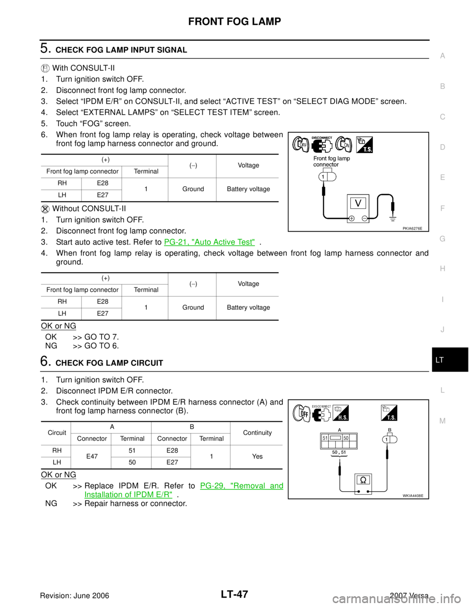
5. CHECK FOG LAMP INPUT SIGNAL
With CONSULT-II
1. Turn ignition switch OFF.
2. Disconnect front fog lamp connector.
3. Select “IPDM E/R” on CONSULT-II, and select “ACTIVE TEST” on “SELECT DIAG MODE” screen.
4. Select “EXTERNAL LAMPS” on “SELECT TEST ITEM” screen.
5. Touch “FOG” screen.
6. When front fog lamp relay is operating, check voltage between
front fog lamp harness connector and ground.
Without CONSULT-II
1. Turn ignition switch OFF.
2. Disconnect front fog lamp connector.
3. Start auto active test. Refer to PG-21, "
Auto Active Test" .
4. When front fog lamp relay is operating, check voltage between front fog lamp harness connector and
ground.
OK or NG
OK >> GO TO 7.
NG >> GO TO 6.
6. CHECK FOG LAMP CIRCUIT
1. Turn ignition switch OFF.
2. Disconnect IPDM E/R connector.
3. Check continuity between IPDM E/R harness connector (A) and
front fog lamp harness connector (B).
OK or NG
OK >> Replace IPDM E/R. Refer to PG-29, "Removal and
Installation of IPDM E/R" .
NG >> Repair harness or connector.
(+)
(−)Voltage
Front fog lamp connector Terminal
RH E28
1 Ground Battery voltage
LH E27
(+)
(−)Voltage
Front fog lamp connector Terminal
RH E28
1 Ground Battery voltage
LH E27
PKIA6276E
CircuitAB
Continuity
Connector Terminal Connector Terminal
RH
E4751 E28
1Yes
LH 50 E27
WKIA4408E
Page 2256 of 2896
LT-48
FRONT FOG LAMP
Revision: June 20062007 Versa
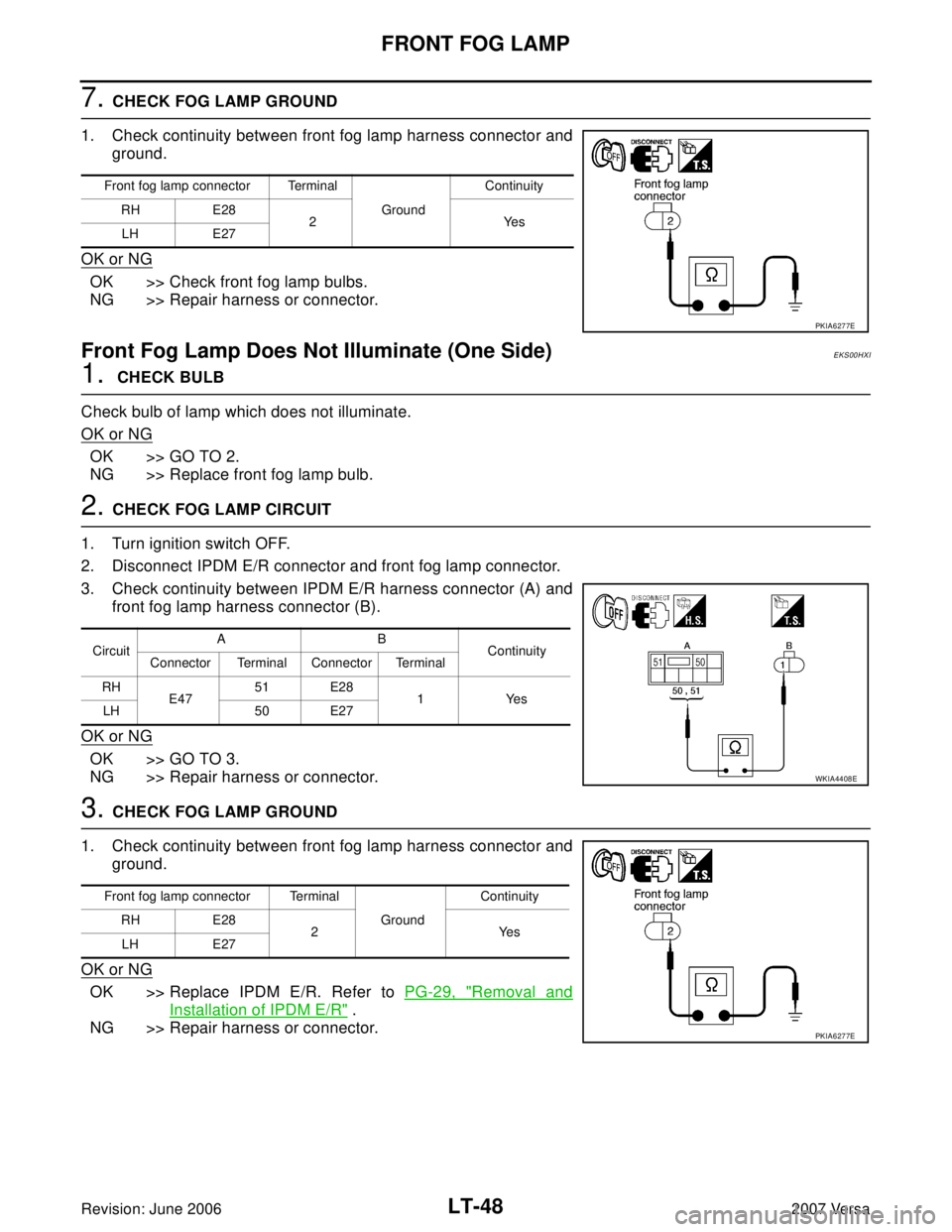
7. CHECK FOG LAMP GROUND
1. Check continuity between front fog lamp harness connector and
ground.
OK or NG
OK >> Check front fog lamp bulbs.
NG >> Repair harness or connector.
Front Fog Lamp Does Not Illuminate (One Side)EKS00HXI
1. CHECK BULB
Check bulb of lamp which does not illuminate.
OK or NG
OK >> GO TO 2.
NG >> Replace front fog lamp bulb.
2. CHECK FOG LAMP CIRCUIT
1. Turn ignition switch OFF.
2. Disconnect IPDM E/R connector and front fog lamp connector.
3. Check continuity between IPDM E/R harness connector (A) and
front fog lamp harness connector (B).
OK or NG
OK >> GO TO 3.
NG >> Repair harness or connector.
3. CHECK FOG LAMP GROUND
1. Check continuity between front fog lamp harness connector and
ground.
OK or NG
OK >> Replace IPDM E/R. Refer to PG-29, "Removal and
Installation of IPDM E/R" .
NG >> Repair harness or connector.
Front fog lamp connector Terminal
Ground Continuity
RH E28
2Yes
LH E27
PKIA6277E
CircuitAB
Continuity
Connector Terminal Connector Terminal
RH
E4751 E28
1Yes
LH 50 E27
WKIA4408E
Front fog lamp connector Terminal
Ground Continuity
RH E28
2Yes
LH E27
PKIA6277E
Page 2259 of 2896
TURN SIGNAL AND HAZARD WARNING LAMPS
LT-51
C
D
E
F
G
H
I
J
L
MA
B
LT
Revision: June 20062007 Versa
TURN SIGNAL AND HAZARD WARNING LAMPSPFP:26120
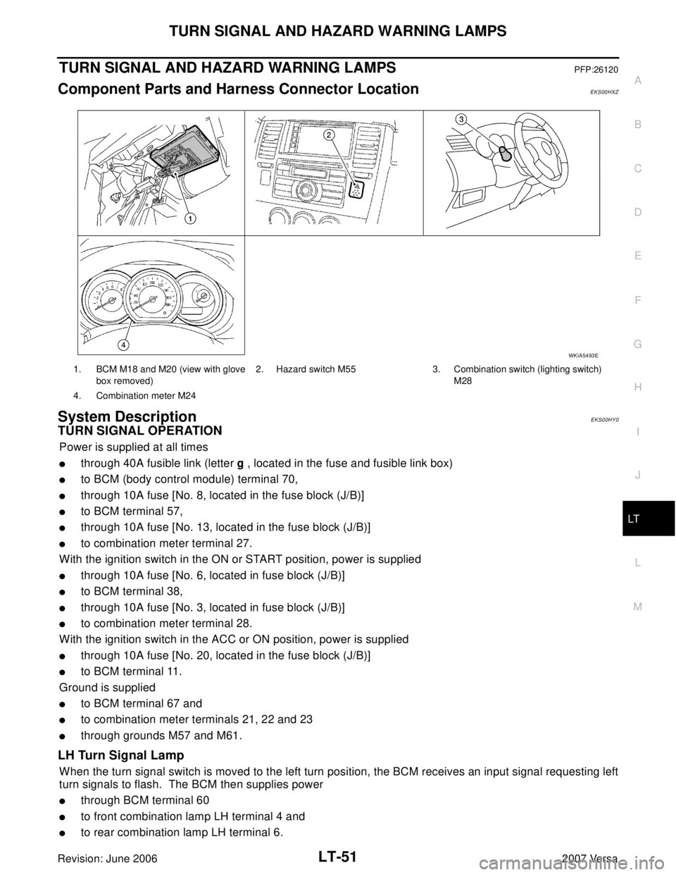
Component Parts and Harness Connector LocationEKS00HXZ
System DescriptionEKS00HY0
TURN SIGNAL OPERATION
Power is supplied at all times
�through 40A fusible link (letter g , located in the fuse and fusible link box)
�to BCM (body control module) terminal 70,
�through 10A fuse [No. 8, located in the fuse block (J/B)]
�to BCM terminal 57,
�through 10A fuse [No. 13, located in the fuse block (J/B)]
�to combination meter terminal 27.
With the ignition switch in the ON or START position, power is supplied
�through 10A fuse [No. 6, located in fuse block (J/B)]
�to BCM terminal 38,
�through 10A fuse [No. 3, located in fuse block (J/B)]
�to combination meter terminal 28.
With the ignition switch in the ACC or ON position, power is supplied
�through 10A fuse [No. 20, located in the fuse block (J/B)]
�to BCM terminal 11.
Ground is supplied
�to BCM terminal 67 and
�to combination meter terminals 21, 22 and 23
�through grounds M57 and M61.
LH Turn Signal Lamp
When the turn signal switch is moved to the left turn position, the BCM receives an input signal requesting left
turn signals to flash. The BCM then supplies power
�through BCM terminal 60
�to front combination lamp LH terminal 4 and
�to rear combination lamp LH terminal 6.
1. BCM M18 and M20 (view with glove
box removed)2. Hazard switch M55 3. Combination switch (lighting switch)
M28
4. Combination meter M24
WKIA5493E
Page 2268 of 2896
LT-60
TURN SIGNAL AND HAZARD WARNING LAMPS
Revision: June 20062007 Versa
2. CHECK FRONT TURN SIGNAL LAMP CIRCUIT
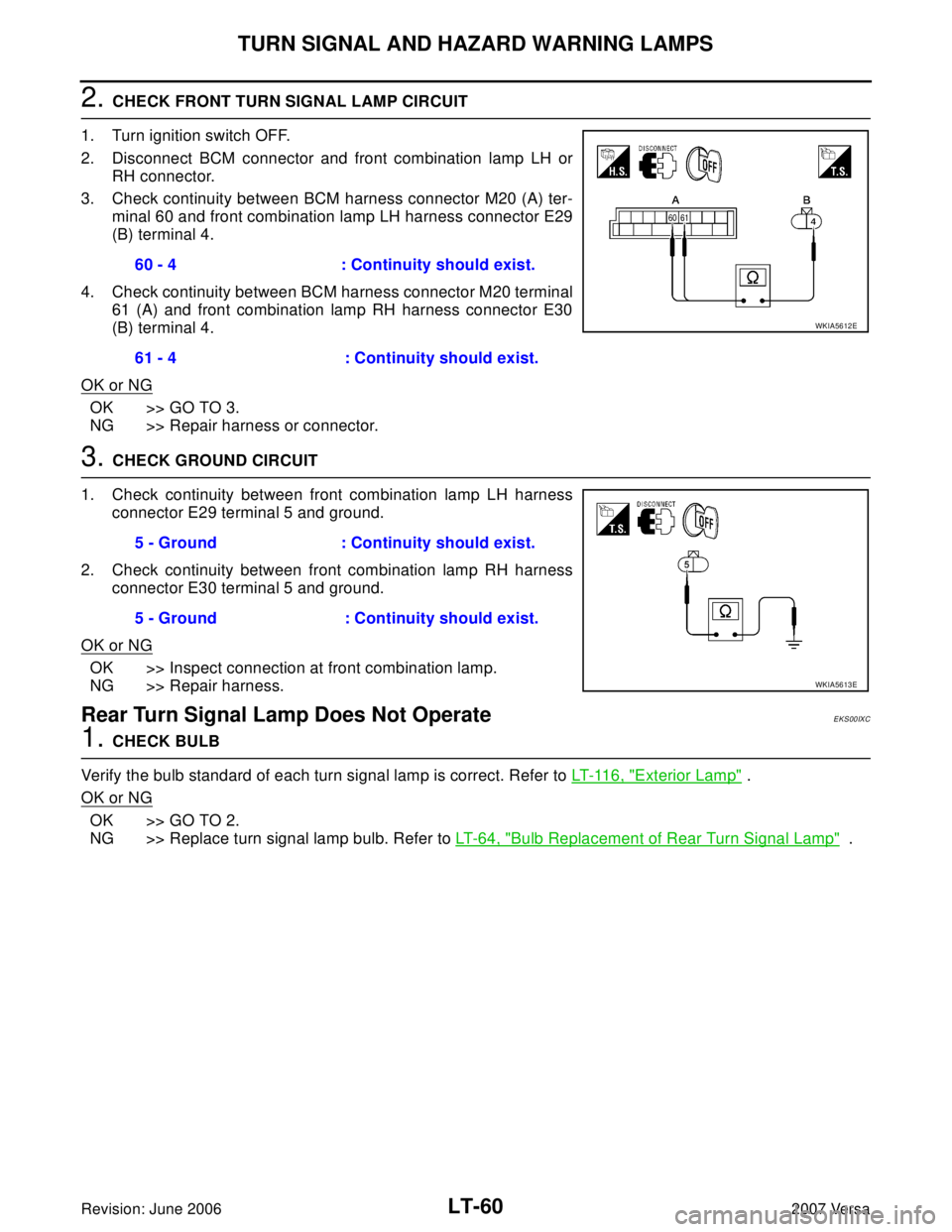
1. Turn ignition switch OFF.
2. Disconnect BCM connector and front combination lamp LH or
RH connector.
3. Check continuity between BCM harness connector M20 (A) ter-
minal 60 and front combination lamp LH harness connector E29
(B) terminal 4.
4. Check continuity between BCM harness connector M20 terminal
61 (A) and front combination lamp RH harness connector E30
(B) terminal 4.
OK or NG
OK >> GO TO 3.
NG >> Repair harness or connector.
3. CHECK GROUND CIRCUIT
1. Check continuity between front combination lamp LH harness
connector E29 terminal 5 and ground.
2. Check continuity between front combination lamp RH harness
connector E30 terminal 5 and ground.
OK or NG
OK >> Inspect connection at front combination lamp.
NG >> Repair harness.
Rear Turn Signal Lamp Does Not OperateEKS00IXC
1. CHECK BULB
Verify the bulb standard of each turn signal lamp is correct. Refer to LT- 11 6 , "
Exterior Lamp" .
OK or NG
OK >> GO TO 2.
NG >> Replace turn signal lamp bulb. Refer to LT- 6 4 , "
Bulb Replacement of Rear Turn Signal Lamp" . 60 - 4 : Continuity should exist.
61 - 4 : Continuity should exist.
WKIA5612E
5 - Ground : Continuity should exist.
5 - Ground : Continuity should exist.
WKIA5613E
Page 2269 of 2896
TURN SIGNAL AND HAZARD WARNING LAMPS
LT-61
C
D
E
F
G
H
I
J
L
MA
B
LT
Revision: June 20062007 Versa
2. CHECK REAR TURN SIGNAL LAMP CIRCUIT
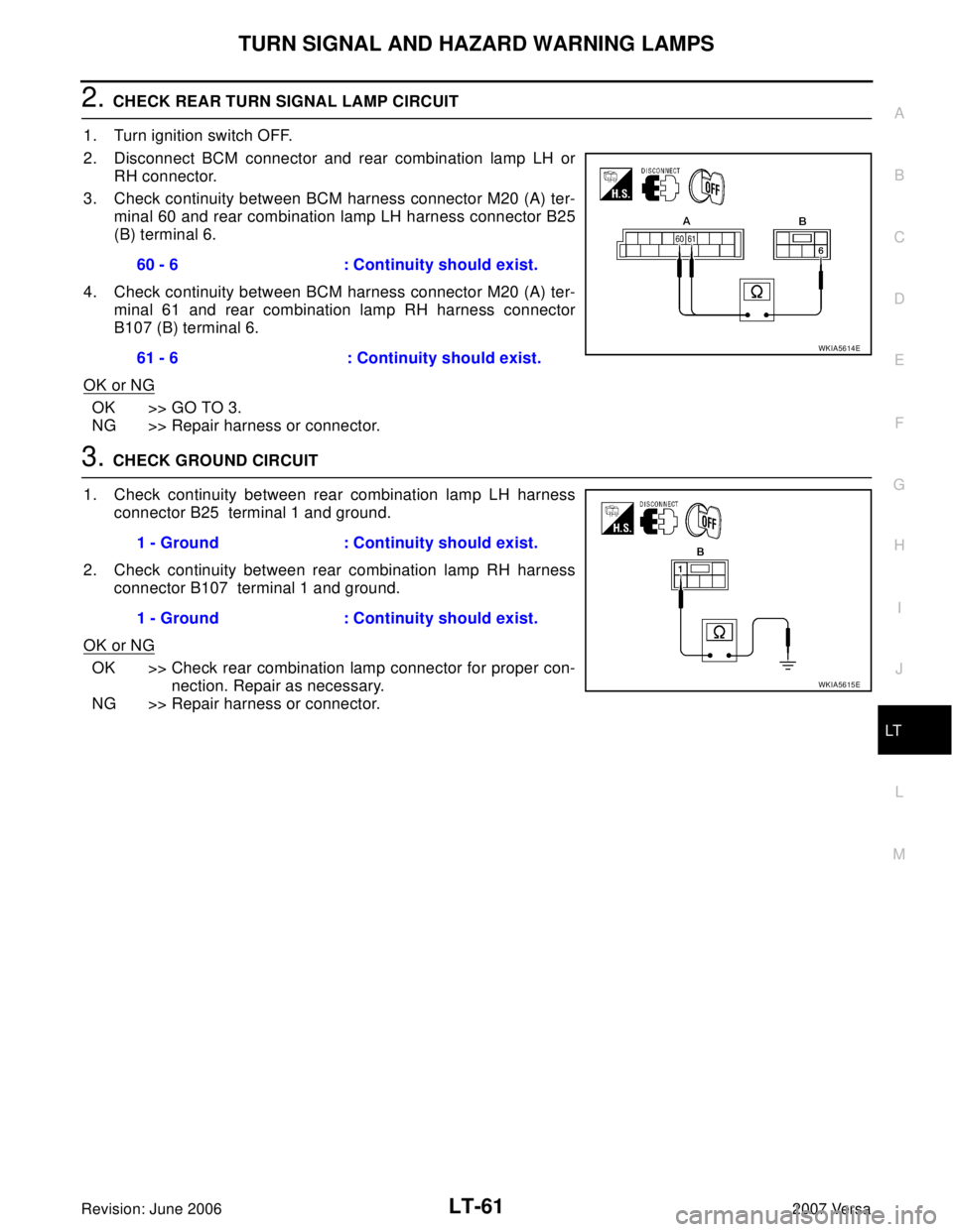
1. Turn ignition switch OFF.
2. Disconnect BCM connector and rear combination lamp LH or
RH connector.
3. Check continuity between BCM harness connector M20 (A) ter-
minal 60 and rear combination lamp LH harness connector B25
(B) terminal 6.
4. Check continuity between BCM harness connector M20 (A) ter-
minal 61 and rear combination lamp RH harness connector
B107 (B) terminal 6.
OK or NG
OK >> GO TO 3.
NG >> Repair harness or connector.
3. CHECK GROUND CIRCUIT
1. Check continuity between rear combination lamp LH harness
connector B25 terminal 1 and ground.
2. Check continuity between rear combination lamp RH harness
connector B107 terminal 1 and ground.
OK or NG
OK >> Check rear combination lamp connector for proper con-
nection. Repair as necessary.
NG >> Repair harness or connector.60 - 6 : Continuity should exist.
61 - 6 : Continuity should exist.
WKIA5614E
1 - Ground : Continuity should exist.
1 - Ground : Continuity should exist.
WKIA5615E
Page 2270 of 2896
LT-62
TURN SIGNAL AND HAZARD WARNING LAMPS
Revision: June 20062007 Versa
Hazard Warning Lamp Does Not Operate But Turn Signal Lamp OperatesEKS00HYA
1. CHECK HAZARD SWITCH INPUT SIGNAL
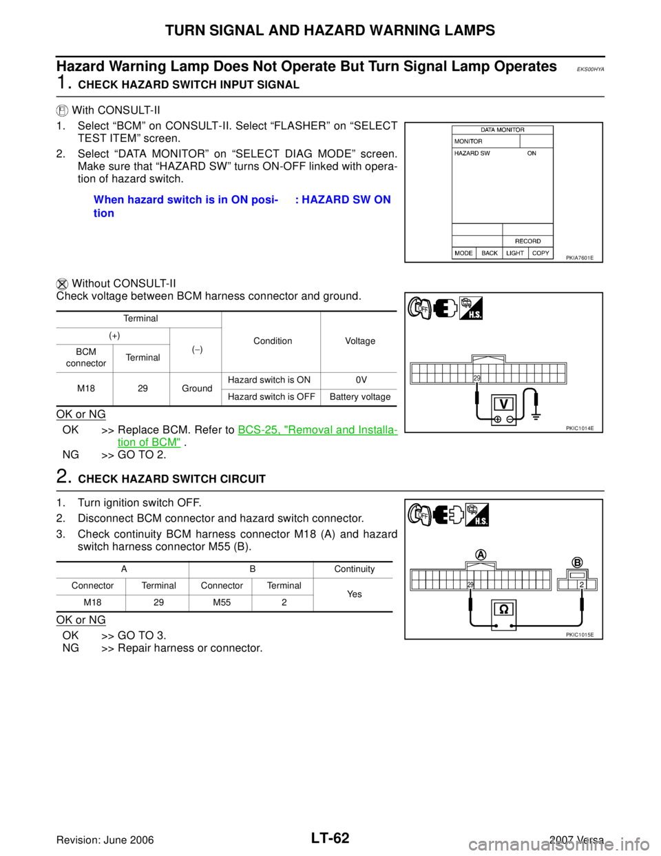
With CONSULT-II
1. Select “BCM” on CONSULT-II. Select “FLASHER” on “SELECT
TEST ITEM” screen.
2. Select “DATA MONITOR” on “SELECT DIAG MODE” screen.
Make sure that “HAZARD SW” turns ON-OFF linked with opera-
tion of hazard switch.
Without CONSULT-II
Check voltage between BCM harness connector and ground.
OK or NG
OK >> Replace BCM. Refer to BCS-25, "Removal and Installa-
tion of BCM" .
NG >> GO TO 2.
2. CHECK HAZARD SWITCH CIRCUIT
1. Turn ignition switch OFF.
2. Disconnect BCM connector and hazard switch connector.
3. Check continuity BCM harness connector M18 (A) and hazard
switch harness connector M55 (B).
OK or NG
OK >> GO TO 3.
NG >> Repair harness or connector.When hazard switch is in ON posi-
tion : HAZARD SW ON
PKIA7601E
Te r m i n a l
Condition Voltage (+)
(−)
BCM
connectorTe r m i n a l
M18 29 GroundHazard switch is ON 0V
Hazard switch is OFF Battery voltage
PKIC1014E
A B Continuity
Connector Terminal Connector Terminal
Ye s
M18 29 M55 2
PKIC1015E