Page 2352 of 2896
MA-18
ENGINE MAINTENANCE
Revision: June 20062007 Versa
2. Apply new engine oil to the oil seal contact surface of new oil fil-
ter.
3. Screw oil filter manually until it touches the installation surface,
then tighten it by 2/3 turn. Or tighten to specification.
INSPECTION AFTER INSTALLATION
1. Check the engine oil level. Refer to LU-5, "ENGINE OIL LEVEL" .
2. Start engine, and make sure there is no leaks of engine oil.
3. Stop engine and wait for 10 minutes.
4. Check the engine oil level and adjust engine oil. Refer to LU-5, "
ENGINE OIL LEVEL" .
Changing Spark PlugsELS0020O
1. Remove intake manifold. Refer to EM-18, "INTAKE MANIFOLD" .
2. Remove ignition coil.
CAUTION:
�Handle ignition coil carefully and avoid impacts.
�Never disassemble.
3. Remove spark plug using suitable tool.
CAUTION:
Never drop or shock it.
INSPECTION AFTER REMOVAL
CAUTION:
�Never drop or shock spark plug.
SM A01 0
Oil filter: : 17.7 N·m (1.8 kg-m, 13 ft-lb)
SM A22 9B
PBIC3871E
Page 2353 of 2896
ENGINE MAINTENANCE
MA-19
C
D
E
F
G
H
I
J
K
MA
B
MA
Revision: June 20062007 Versa
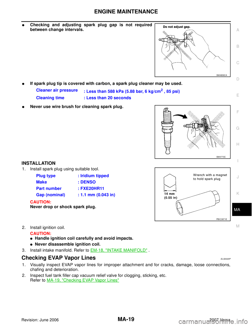
�Checking and adjusting spark plug gap is not required
between change intervals.
�If spark plug tip is covered with carbon, a spark plug cleaner may be used.
�Never use wire brush for cleaning spark plug.
INSTALLATION
1. Install spark plug using suitable tool.
CAUTION:
Never drop or shock spark plug.
2. Install ignition coil.
CAUTION:
�Handle ignition coil carefully and avoid impacts.
�Never disassemble ignition coil.
3. Install intake manifold. Refer to EM-18, "
INTAKE MANIFOLD" .
Checking EVAP Vapor LinesELS0020P
1. Visually inspect EVAP vapor lines for improper attachment and for cracks, damage, loose connections,
chafing and deterioration.
2. Inspect fuel tank filler cap vacuum relief valve for clogging, sticking, etc.
Refer to MA-19, "
Checking EVAP Vapor Lines"
SM A80 6CA
Cleaner air pressure
: Less than 588 kPa (5.88 bar, 6 kg/cm2 , 85 psi)
Cleaning time : Less than 20 seconds
SM A77 3C
Plug type : Iridium tipped
Make : DENSO
Part number : FXE20HR11
Gap (nominal) : 1.1 mm (0.043 in)
PBIC3871E
Page 2436 of 2896
MTC-24
TROUBLE DIAGNOSIS
Revision: June 20062007 Versa
TROUBLE DIAGNOSISPFP:00004
CONSULT-II Function (BCM)EJS0057E
CONSULT-II can display each diagnostic item using the diagnostic test modes shown following.
CONSULT-II START PROCEDURE
Refer to GI-38, "CONSULT-II Start Procedure" .
DATA MONITOR
Display Item List
How to Perform Trouble Diagnosis for Quick and Accurate RepairEJS0057F
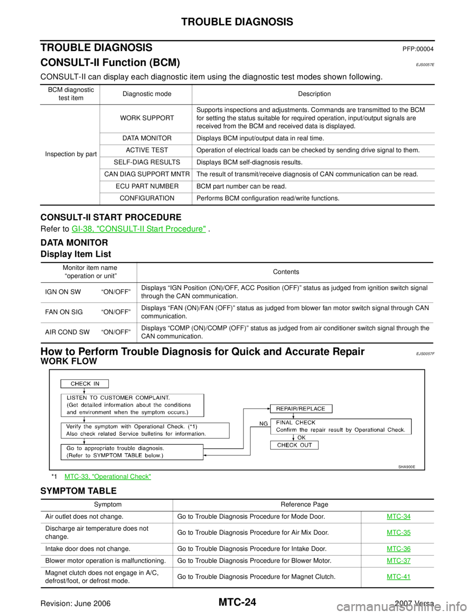
WORK FLOW
SYMPTOM TABLE
BCM diagnostic
test itemDiagnostic mode Description
Inspection by partWORK SUPPORTSupports inspections and adjustments. Commands are transmitted to the BCM
for setting the status suitable for required operation, input/output signals are
received from the BCM and received data is displayed.
DATA MONITOR Displays BCM input/output data in real time.
ACTIVE TEST Operation of electrical loads can be checked by sending drive signal to them.
SELF-DIAG RESULTS Displays BCM self-diagnosis results.
CAN DIAG SUPPORT MNTR The result of transmit/receive diagnosis of CAN communication can be read.
ECU PART NUMBER BCM part number can be read.
CONFIGURATION Performs BCM configuration read/write functions.
Monitor item name
“operation or unit”Contents
IGN ON SW “ON/OFF”Displays “IGN Position (ON)/OFF, ACC Position (OFF)” status as judged from ignition switch signal
through the CAN communication.
FAN ON SIG “ON/OFF”Displays “FAN (ON)/FAN (OFF)” status as judged from blower fan motor switch signal through CAN
communication.
AIR COND SW “ON/OFF”Displays “COMP (ON)/COMP (OFF)” status as judged from air conditioner switch signal through the
CAN communication.
*1MTC-33, "Operational Check"
SHA9 00 E
Symptom Reference Page
Air outlet does not change. Go to Trouble Diagnosis Procedure for Mode Door.MTC-34
Discharge air temperature does not
change.Go to Trouble Diagnosis Procedure for Air Mix Door.MTC-35
Intake door does not change. Go to Trouble Diagnosis Procedure for Intake Door.MTC-36
Blower motor operation is malfunctioning. Go to Trouble Diagnosis Procedure for Blower Motor.MTC-37
Magnet clutch does not engage in A/C,
defrost/foot, or defrost mode.Go to Trouble Diagnosis Procedure for Magnet Clutch.MTC-41
Page 2450 of 2896
MTC-38
TROUBLE DIAGNOSIS
Revision: June 20062007 Versa
DIAGNOSTIC PROCEDURE FOR BLOWER MOTOR
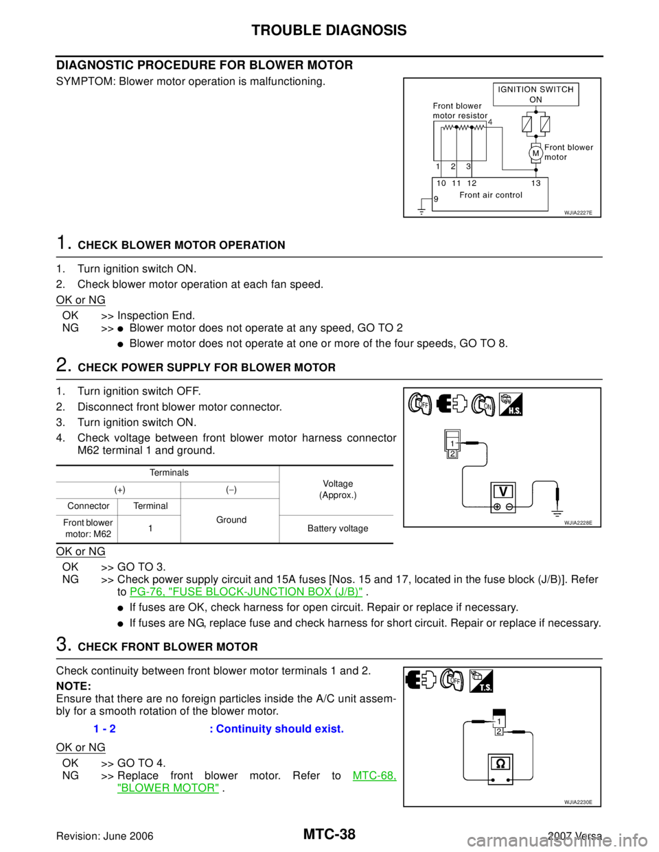
SYMPTOM: Blower motor operation is malfunctioning.
1. CHECK BLOWER MOTOR OPERATION
1. Turn ignition switch ON.
2. Check blower motor operation at each fan speed.
OK or NG
OK >> Inspection End.
NG >>
�Blower motor does not operate at any speed, GO TO 2
�Blower motor does not operate at one or more of the four speeds, GO TO 8.
2. CHECK POWER SUPPLY FOR BLOWER MOTOR
1. Turn ignition switch OFF.
2. Disconnect front blower motor connector.
3. Turn ignition switch ON.
4. Check voltage between front blower motor harness connector
M62 terminal 1 and ground.
OK or NG
OK >> GO TO 3.
NG >> Check power supply circuit and 15A fuses [Nos. 15 and 17, located in the fuse block (J/B)]. Refer
to PG-76, "
FUSE BLOCK-JUNCTION BOX (J/B)" .
�If fuses are OK, check harness for open circuit. Repair or replace if necessary.
�If fuses are NG, replace fuse and check harness for short circuit. Repair or replace if necessary.
3. CHECK FRONT BLOWER MOTOR
Check continuity between front blower motor terminals 1 and 2.
NOTE:
Ensure that there are no foreign particles inside the A/C unit assem-
bly for a smooth rotation of the blower motor.
OK or NG
OK >> GO TO 4.
NG >> Replace front blower motor. Refer to MTC-68,
"BLOWER MOTOR" .
WJIA2227E
Terminals
Vo ltag e
(Approx.) (+) (−)
Connector Terminal
Ground
Front blower
motor: M621 Battery voltage
WJIA2228E
1 - 2 : Continuity should exist.
WJIA2230E
Page 2452 of 2896
MTC-40
TROUBLE DIAGNOSIS
Revision: June 20062007 Versa
7. CHECK FAN SWITCH GROUND CIRCUIT
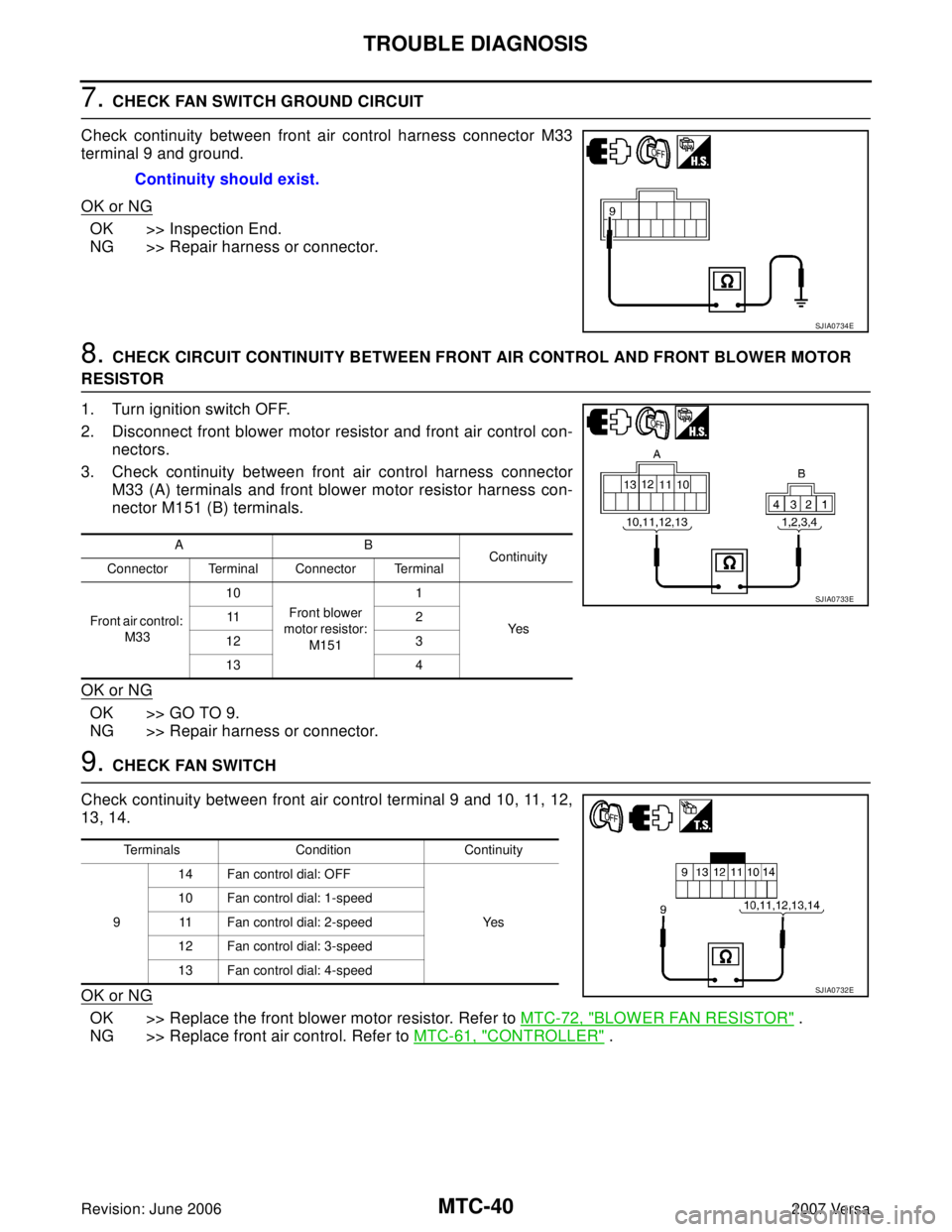
Check continuity between front air control harness connector M33
terminal 9 and ground.
OK or NG
OK >> Inspection End.
NG >> Repair harness or connector.
8. CHECK CIRCUIT CONTINUITY BETWEEN FRONT AIR CONTROL AND FRONT BLOWER MOTOR
RESISTOR
1. Turn ignition switch OFF.
2. Disconnect front blower motor resistor and front air control con-
nectors.
3. Check continuity between front air control harness connector
M33 (A) terminals and front blower motor resistor harness con-
nector M151 (B) terminals.
OK or NG
OK >> GO TO 9.
NG >> Repair harness or connector.
9. CHECK FAN SWITCH
Check continuity between front air control terminal 9 and 10, 11, 12,
13, 14.
OK or NG
OK >> Replace the front blower motor resistor. Refer to MTC-72, "BLOWER FAN RESISTOR" .
NG >> Replace front air control. Refer to MTC-61, "
CONTROLLER" . Continuity should exist.
SJIA0734E
AB
Continuity
Connector Terminal Connector Terminal
Front air control:
M3310
Front blower
motor resistor:
M1511
Ye s 11 2
12 3
13 4
SJIA0733E
Terminals Condition Continuity
914 Fan control dial: OFF
Ye s 10 Fan control dial: 1-speed
11 Fan control dial: 2-speed
12 Fan control dial: 3-speed
13 Fan control dial: 4-speed
SJIA0732E
Page 2453 of 2896
TROUBLE DIAGNOSIS
MTC-41
C
D
E
F
G
H
I
K
L
MA
B
MTC
Revision: June 20062007 Versa
Magnet Clutch Circuit (If Equipped)EJS0057O
SYMPTOM: Magnet clutch does not engage.
INSPECTION FLOW
1. CONFIRM SYMPTOM BY PERFORMING OPERATIONAL CHECK - MAGNET CLUTCH
1. Turn ignition switch ON.
2. Turn blower control dial to the desired (1 to 4 speed) position.
3. Press the A/C switch. A/C indicator will turn on.
4. Confirm that the compressor clutch engages (sound or visual inspection).
Can the symptom be duplicated?
YES >> GO TO 3.
NO >> GO TO 2.
2. CHECK FOR ANY SYMPTOMS
Perform a complete operational check for any symptoms. Refer to MTC-33, "
Operational Check" .
Does another symptom exist?
YES >> Refer to MTC-24, "SYMPTOM TABLE" .
NO >> System OK.
3. CHECK FOR SERVICE BULLETINS
Check for any service bulletins.
>> GO TO 4.
4. CHECK COMPRESSOR BELT TENSION
Check compressor belt tension. Refer to EM-13, "
Checking Drive Belts" .
OK or NG
OK >> GO TO 5.
NG >> Adjust or replace A/C compressor belt.
5. CHECK REFRIGERANT PRESSURE
Check refrigerant pressure with manifold gauge connected. Refer to MTC-54, "
Test Reading" .
OK or NG
OK >> GO TO 6.
NG >> Perform trouble diagnosis for unusual pressure. Refer to MTC-55, "
TROUBLE DIAGNOSIS FOR
UNUSUAL PRESSURE" .
6. CHECK MAGNET CLUTCH CIRCUIT
Perform diagnostic procedure for the magnetic clutch. Refer to MTC-42, "
DIAGNOSTIC PROCEDURE FOR
MAGNET CLUTCH" .
OK or NG
OK >> If the symptom still exists, perform a complete operational check. Refer to MTC-33, "Operational
Check" . If other symptoms exist, refer to MTC-24, "SYMPTOM TABLE" .
NG >> Repair as necessary.
Page 2455 of 2896
TROUBLE DIAGNOSIS
MTC-43
C
D
E
F
G
H
I
K
L
MA
B
MTC
Revision: June 20062007 Versa
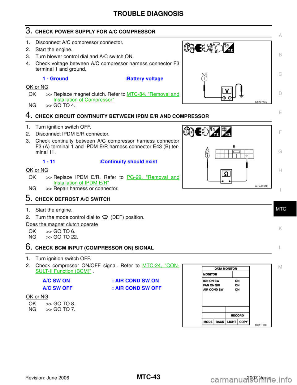
3. CHECK POWER SUPPLY FOR A/C COMPRESSOR
1. Disconnect A/C compressor connector.
2. Start the engine.
3. Turn blower control dial and A/C switch ON.
4. Check voltage between A/C compressor harness connector F3
terminal 1 and ground.
OK or NG
OK >> Replace magnet clutch. Refer to MTC-84, "Removal and
Installation of Compressor"
NG >> GO TO 4.
4. CHECK CIRCUIT CONTINUITY BETWEEN IPDM E/R AND COMPRESSOR
1. Turn ignition switch OFF.
2. Disconnect IPDM E/R connector.
3. Check continuity between A/C compressor harness connector
F3 (A) terminal 1 and IPDM E/R harness connector E43 (B) ter-
minal 11.
OK or NG
OK >> Replace IPDM E/R. Refer to PG-29, "Removal and
Installation of IPDM E/R"
NG >> Repair harness or connector.
5. CHECK DEFROST A/C SWITCH
1. Start the engine.
2. Turn the mode control dial to (DEF) position.
Does the magnet clutch operate
OK >> GO TO 6.
NG >> GO TO 22.
6. CHECK BCM INPUT (COMPRESSOR ON) SIGNAL
1. Turn ignition switch OFF.
2. Check compressor ON/OFF signal. Refer to MTC-24, "
CON-
SULT-II Function (BCM)" .
OK or NG
OK >> GO TO 8.
NG >> GO TO 7.1 - Ground :Battery voltage
SJIA0743E
1 - 11 :Continuity should exist
WJIA2233E
A/C SW ON : AIR COND SW ON
A/C SW OFF : AIR COND SW OFF
R J I A 1111E
Page 2456 of 2896
MTC-44
TROUBLE DIAGNOSIS
Revision: June 20062007 Versa
7. CHECK CIRCUIT CONTINUITY BETWEEN FRONT AIR CONTROL AND BCM
1. Turn ignition switch OFF.
2. Disconnect front air control and BCM connector.
3. Check continuity between front air control harness connector
M33 (A) terminal 1and BCM harness connector M18 (B) termi-
nal 27.
OK or NG
OK >> GO TO 8.
NG >> Repair harness or connector.
8. CHECK REFRIGERANT PRESSURE SENSOR
1. Reconnect front air control connector and BCM connector.
2. Check refrigerant pressure sensor. Refer to EC-586, "
REFRIGERANT PRESSURE SENSOR" .
.OK or NG
OK >>�WITH CONSULT-II
GO TO 9.
�WITHOUT CONSULT-II
GO TO 10.
NG >> Replace as necessary.
9. CHECK BCM INPUT (FAN ON) SIGNAL
Check FAN ON/OFF signal. Refer to MTC-24, "
CONSULT-II Func-
tion (BCM)" .
OK or NG
OK >> GO TO 12.
NG >> GO TO 10.1 - 27 :Continuity should exist
SJIA0759E
FAN CONTROL DIAL ON : FAN ON SIG ON
FAN CONTROL DIAL OFF : FAN ON SIG OFF
R J I A 1111E