Page 2277 of 2896
COMBINATION SWITCH
LT-69
C
D
E
F
G
H
I
J
L
MA
B
LT
Revision: June 20062007 Versa
3. HARNESS INSPECTION
1. Turn ignition switch OFF.
2. Disconnect BCM connector and combination switch connector.
3. Check for continuity between BCM harness connector of the suspect system and the corresponding com-
bination switch harness connector.
4. Check for continuity between of BCM harness connector in suspect system and ground.
OK or NG
OK >> GO TO 4.
NG >> Check harness between BCM and combination switch for open or short circuit.
Suspect
systemAB
Continuity
Connector Terminal Connector Terminal
1
M18Input 1 6
M286
Ye s Output 1 36 1
2Input 2 5 7
Output 2 35 2
3Input 3 4 10
Output 3 34 3
4Input 4 3 9
Output 4 33 4
5Input 5 2 8
Output 5 32 5
Suspect
systemBCM
Continuity
Connector Terminal
1
M18Input 1 6
Ground No Output 1 36
2Input 2 5
Output 2 35
3Input 3 4
Output 3 34
4Input 4 3
Output 4 33
5Input 5 2
Output 5 32
WKIA5497E
WKIA5500E
Page 2278 of 2896
LT-70
COMBINATION SWITCH
Revision: June 20062007 Versa
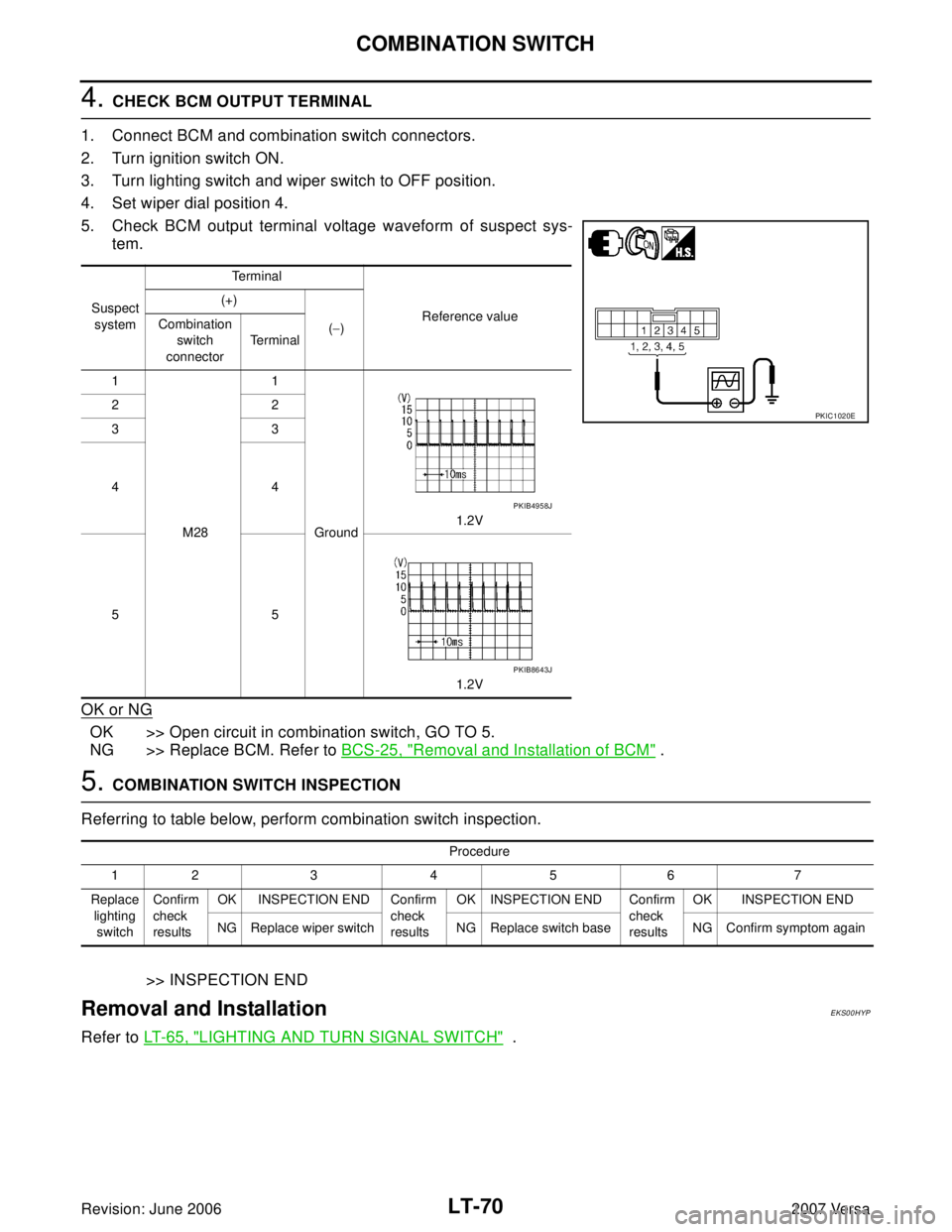
4. CHECK BCM OUTPUT TERMINAL
1. Connect BCM and combination switch connectors.
2. Turn ignition switch ON.
3. Turn lighting switch and wiper switch to OFF position.
4. Set wiper dial position 4.
5. Check BCM output terminal voltage waveform of suspect sys-
tem.
OK or NG
OK >> Open circuit in combination switch, GO TO 5.
NG >> Replace BCM. Refer to BCS-25, "
Removal and Installation of BCM" .
5. COMBINATION SWITCH INSPECTION
Referring to table below, perform combination switch inspection.
>> INSPECTION END
Removal and InstallationEKS00HYP
Refer to LT- 6 5 , "LIGHTING AND TURN SIGNAL SWITCH" .
Suspect
systemTe r m i n a l
Reference value (+)
(−) Combination
switch
connectorTe r m i n a l
1
M281
Ground1.2V 22
33
44
55
1.2V
PKIC1020E
PKIB4958J
PKIB8643J
Procedure
12 3 4 5 6 7
Replace
lighting
switchConfirm
check
resultsOK INSPECTION END Confirm
check
resultsOK INSPECTION END Confirm
check
resultsOK INSPECTION END
NG Replace wiper switch NG Replace switch base NG Confirm symptom again
Page 2283 of 2896
PARKING, LICENSE PLATE AND TAIL LAMPS
LT-75
C
D
E
F
G
H
I
J
L
MA
B
LT
Revision: June 20062007 Versa
PARKING, LICENSE PLATE AND TAIL LAMPSPFP:26550
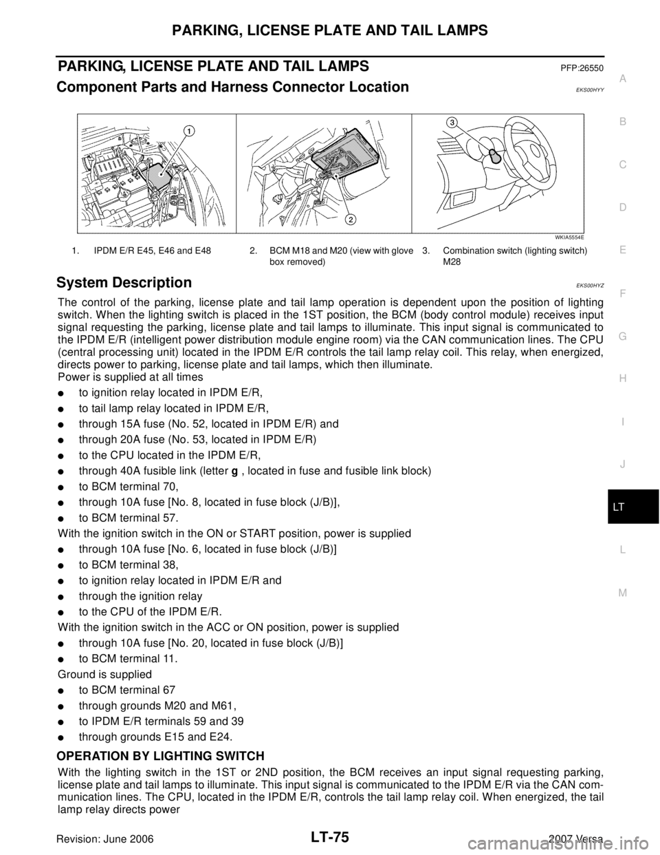
Component Parts and Harness Connector LocationEKS00HYY
System DescriptionEKS00HYZ
The control of the parking, license plate and tail lamp operation is dependent upon the position of lighting
switch. When the lighting switch is placed in the 1ST position, the BCM (body control module) receives input
signal requesting the parking, license plate and tail lamps to illuminate. This input signal is communicated to
the IPDM E/R (intelligent power distribution module engine room) via the CAN communication lines. The CPU
(central processing unit) located in the IPDM E/R controls the tail lamp relay coil. This relay, when energized,
directs power to parking, license plate and tail lamps, which then illuminate.
Power is supplied at all times
�to ignition relay located in IPDM E/R,
�to tail lamp relay located in IPDM E/R,
�through 15A fuse (No. 52, located in IPDM E/R) and
�through 20A fuse (No. 53, located in IPDM E/R)
�to the CPU located in the IPDM E/R,
�through 40A fusible link (letter g , located in fuse and fusible link block)
�to BCM terminal 70,
�through 10A fuse [No. 8, located in fuse block (J/B)],
�to BCM terminal 57.
With the ignition switch in the ON or START position, power is supplied
�through 10A fuse [No. 6, located in fuse block (J/B)]
�to BCM terminal 38,
�to ignition relay located in IPDM E/R and
�through the ignition relay
�to the CPU of the IPDM E/R.
With the ignition switch in the ACC or ON position, power is supplied
�through 10A fuse [No. 20, located in fuse block (J/B)]
�to BCM terminal 11.
Ground is supplied
�to BCM terminal 67
�through grounds M20 and M61,
�to IPDM E/R terminals 59 and 39
�through grounds E15 and E24.
OPERATION BY LIGHTING SWITCH
With the lighting switch in the 1ST or 2ND position, the BCM receives an input signal requesting parking,
license plate and tail lamps to illuminate. This input signal is communicated to the IPDM E/R via the CAN com-
munication lines. The CPU, located in the IPDM E/R, controls the tail lamp relay coil. When energized, the tail
lamp relay directs power
1. IPDM E/R E45, E46 and E48 2. BCM M18 and M20 (view with glove
box removed)3. Combination switch (lighting switch)
M28
WKIA5554E
Page 2284 of 2896

LT-76
PARKING, LICENSE PLATE AND TAIL LAMPS
Revision: June 20062007 Versa
�through 10A fuse (No. 37, located in IPDM E/R),
�through IPDM E/R terminal 26
�to front combination lamp LH terminal 6, and
�through IPDM E/R terminal 27
�to front combination lamp RH terminal 6,
�through IPDM E/R terminal 28
�to rear combination lamp LH terminal 4 and
�to license plate lamp LH and RH terminal 1,
�through IPDM E/R terminal 29
�to rear combination lamp RH terminal 4.
Ground is supplied
�to front combination lamp LH and RH terminal 7
�through grounds E15 and E24,
�to rear combination lamp LH terminal 1 and
�to license plate lamp LH and RH terminal 2
�through grounds B7 and B19, and
�to rear combination lamp RH terminal 1
�through grounds B117, B132 and D402.
With power and ground supplied, parking, license plate and tail lamps illuminate.
COMBINATION SWITCH READING FUNCTION
Refer to BCS-3, "COMBINATION SWITCH READING FUNCTION" .
EXTERIOR LAMP BATTERY SAVER CONTROL
When the combination switch (lighting switch) is in the 1ST (or 2ND) position and the ignition switch is turned
from ON or ACC to OFF, the battery saver control feature is activated.
Under this condition, the parking, license and tail lamps remain illuminated for 5 minutes, then the parking,
license plate and tail lamps are turned off.
Exterior lamp battery saver control mode can be changed by the function setting of CONSULT-II.
CAN Communication System DescriptionEKS00HZ0
Refer to LAN-4, "CAN Communication System" .
Page 2291 of 2896
PARKING, LICENSE PLATE AND TAIL LAMPS
LT-83
C
D
E
F
G
H
I
J
L
MA
B
LT
Revision: June 20062007 Versa
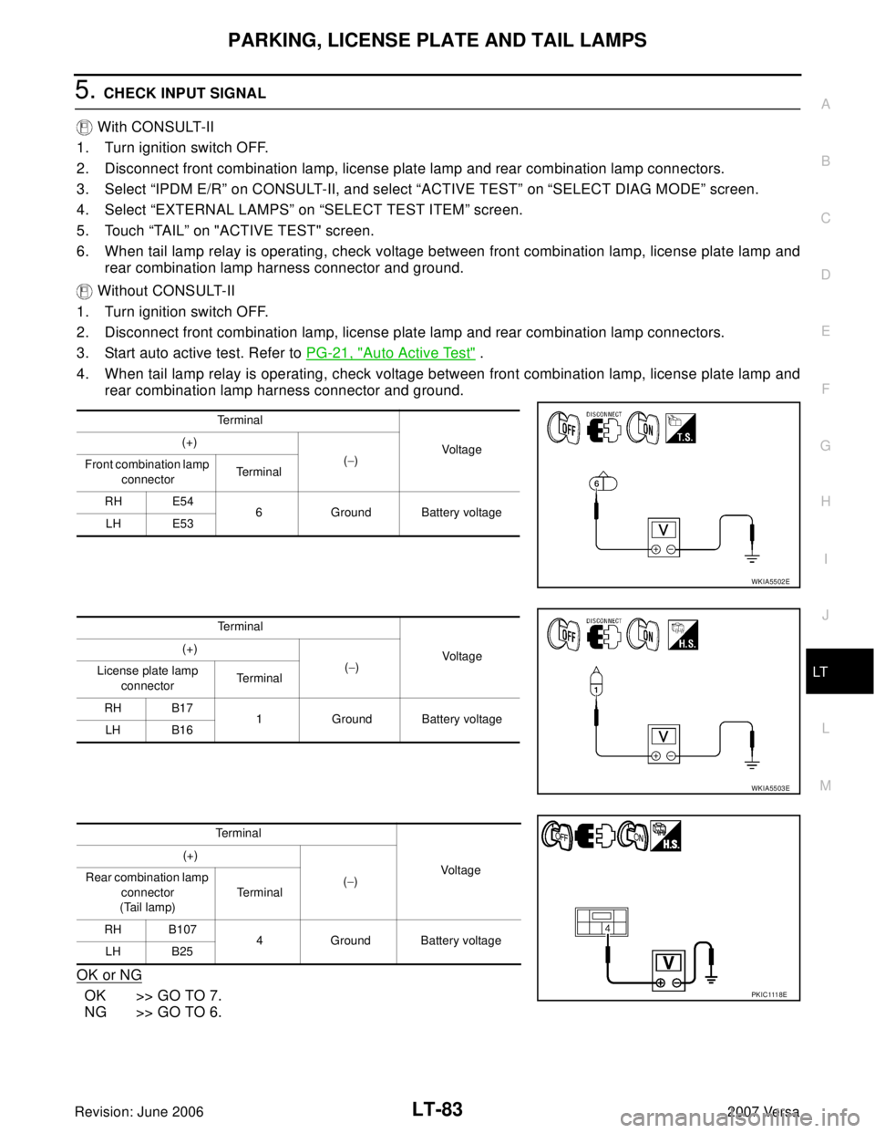
5. CHECK INPUT SIGNAL
With CONSULT-II
1. Turn ignition switch OFF.
2. Disconnect front combination lamp, license plate lamp and rear combination lamp connectors.
3. Select “IPDM E/R” on CONSULT-II, and select “ACTIVE TEST” on “SELECT DIAG MODE” screen.
4. Select “EXTERNAL LAMPS” on “SELECT TEST ITEM” screen.
5. Touch “TAIL” on "ACTIVE TEST" screen.
6. When tail lamp relay is operating, check voltage between front combination lamp, license plate lamp and
rear combination lamp harness connector and ground.
Without CONSULT-II
1. Turn ignition switch OFF.
2. Disconnect front combination lamp, license plate lamp and rear combination lamp connectors.
3. Start auto active test. Refer to PG-21, "
Auto Active Test" .
4. When tail lamp relay is operating, check voltage between front combination lamp, license plate lamp and
rear combination lamp harness connector and ground.
OK or NG
OK >> GO TO 7.
NG >> GO TO 6.
Te r m i n a l
Voltage (+)
(−)
Front combination lamp
connectorTe r m i n a l
RH E54
6 Ground Battery voltage
LH E53
WKIA5502E
Te r m i n a l
Voltage (+)
(−)
License plate lamp
connectorTe r m i n a l
RH B17
1 Ground Battery voltage
LH B16
WKIA5503E
Terminal
Voltag e (+)
(−) Rear combination lamp
connector
(Tail lamp)Te r m i n a l
RH B107
4 Ground Battery voltage
LH B25
PK I C 111 8E
Page 2292 of 2896
LT-84
PARKING, LICENSE PLATE AND TAIL LAMPS
Revision: June 20062007 Versa
6. CHECK PARKING, LICENSE PLATE AND TAIL LAMP CIRCUIT
1. Turn ignition switch OFF.
2. Disconnect IPDM E/R connector.
3. Check continuity between IPDM E/R harness connector (A) and
front combination lamp harness connector (B).
4. Check continuity between IPDM E/R harness connector (A) and
license plate lamp harness connector (B).
5. Check continuity between IPDM E/R harness connector (A) and
rear combination lamp harness connector (B).
OK or NG
OK >> Replace IPDM E/R. Refer to PG-29, "Removal and
Installation of IPDM E/R" .
NG >> Repair harness or connector.
AB
Continuity
Connector Terminal Connector Terminal
E4527 RH E54
6Yes
26 LH E53
WKIA5505E
AB
Continuity
Connector Terminal Connector Terminal
E45 28RH B17
1Yes
LH B16
WKIA5506E
AB
Continuity
Connector Terminal Connector Terminal
E4529 RH B107
4Yes
28 LH B25
WKIA5508E
Page 2293 of 2896
PARKING, LICENSE PLATE AND TAIL LAMPS
LT-85
C
D
E
F
G
H
I
J
L
MA
B
LT
Revision: June 20062007 Versa
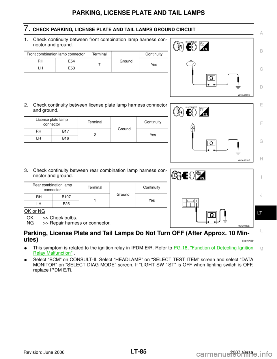
7. CHECK PARKING, LICENSE PLATE AND TAIL LAMPS GROUND CIRCUIT
1. Check continuity between front combination lamp harness con-
nector and ground.
2. Check continuity between license plate lamp harness connector
and ground.
3. Check continuity between rear combination lamp harness con-
nector and ground.
OK or NG
OK >> Check bulbs.
NG >> Repair harness or connector.
Parking, License Plate and Tail Lamps Do Not Turn OFF (After Approx. 10 Min-
utes)
EKS00HZB
�This symptom is related to the ignition relay in IPDM E/R. Refer to PG-18, "Function of Detecting Ignition
Relay Malfunction" .
�Select “BCM” on CONSULT-II. Select “HEADLAMP” on “SELECT TEST ITEM” screen and select “DATA
MONITOR” on “SELECT DIAG MODE” screen. If “LIGHT SW 1ST” is OFF when lighting switch is OFF,
replace IPDM E/R.
Front combination lamp connector Terminal
GroundContinuity
RH E54
7Yes
LH E53
WKIA5509E
License plate lamp
connectorTe r m i n a l
GroundContinuity
RH B17
2 Yes
LH B16
WKIA5510E
Rear combination lamp
connectorTe r m i n a l
GroundContinuity
RH B107
1Yes
LH B25
PKIC1029E
Page 2299 of 2896
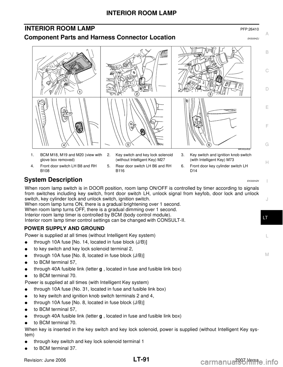
INTERIOR ROOM LAMP
LT-91
C
D
E
F
G
H
I
J
L
MA
B
LT
Revision: June 20062007 Versa
INTERIOR ROOM LAMPPFP:26410
Component Parts and Harness Connector LocationEKS00HZJ
System DescriptionEKS00HZK
When room lamp switch is in DOOR position, room lamp ON/OFF is controlled by timer according to signals
from switches including key switch, front door switch LH, unlock signal from keyfob, door lock and unlock
switch, key cylinder lock and unlock switch, ignition switch.
When room lamp turns ON, there is a gradual brightening over 1 second.
When room lamp turns OFF, there is a gradual dimming over 1 second.
Interior room lamp timer is controlled by BCM (body control module).
Interior room lamp timer control settings can be changed with CONSULT-II.
POWER SUPPLY AND GROUND
Power is supplied at all times (without Intelligent Key system)
�through 10A fuse [No. 14, located in fuse block (J/B)]
�to key switch and key lock solenoid terminal 2,
�through 10A fuse [No. 8, located in fuse block (J/B)]
�to BCM terminal 57,
�through 40A fusible link (letter g , located in fuse and fusible link box)
�to BCM terminal 70.
Power is supplied at all times (with Intelligent Key system)
�through 10A fuse (No. 31, located in fuse and fusible link box)
�to key switch and ignition knob switch terminals 2 and 4,
�through 10A fuse [No. 8, located in fuse block (J/B)]
�to BCM terminal 57,
�through 40A fusible link (letter g , located in fuse and fusible link box)
�to BCM terminal 70.
When key is inserted in the key switch and key lock solenoid, power is supplied (without Intelligent Key sys-
tem)
�through key switch and key lock solenoid terminal 1
�to BCM terminal 37.
1. BCM M18, M19 and M20 (view with
glove box removed)2. Key switch and key lock solenoid
(without Intelligent Key) M273. Key switch and ignition knob switch
(with Intelligent Key) M73
4. Front door switch LH B8 and RH
B1085. Rear door switch LH B6 and RH
B1166. Front door key cylinder switch LH
D14
WKIA5545E