Page 2365 of 2896

PREPARATION
MT-3
D
E
F
G
H
I
J
K
L
MA
B
MT
Revision: June 20062007 Versa
PREPARATIONPFP:00002
Special Service ToolsUCS00655
The actual shapes of Kent-Moore tools may differ from those of special service tools illustrated here.
Tool number
(Kent-Moore No.)
Tool nameDescription
KV381054S0
(J-34286)
PullerRemoving mainshaft front bearing outer race
KV38100200
(—)
Drift
�Installing mainshaft front bearing outer race
�Installing mainshaft rear bearing outer race
�Installing differential side bearing outer race
(clutch housing side)
a: 65 mm (2.56 in) dia.
b: 49 mm (1.93 in) dia.
ST33220000
(—)
DriftInstalling input shaft oil seal
a: 37 mm (1.46 in) dia.
b: 31 mm (1.22 in) dia.
c: 22 mm (0.87 in) dia.
ST33400001
(J-26082)
DriftInstalling differential side bearing outer race
(transaxle case side)
a: 60 mm (2.36 in) dia.
b: 47 mm (1.85 in) dia.
KV38100300
(J-25523)
DriftInstalling differential side oil seal
a: 54 mm (2.13 in) dia.
b: 46 mm (1.81 in) dia.
c: 32 mm (1.26 in) dia.
ST36720030
(—)
Drift
�Installing input shaft rear bearing
�Installing mainshaft front bearing inner race
a: 70 mm (2.76 in) dia.
b: 40 mm (1.57 in) dia.
c: 29 mm (1.14 in) dia.
ZZA0601D
ZZA1143D
ZZA1046D
ZZA0814D
ZZA1046D
ZZA0978D
Page 2366 of 2896

Drift�Removing mainshaft rear bearing inner race
�Removing 6th main gear
�Removing 5th main gear
�Remov")
MT-4
PREPARATION
Revision: June 20062007 Versa
Commercial Service ToolsUCS00656
ST33052000
(—)
Drift�Removing mainshaft rear bearing inner race
�Removing 6th main gear
�Removing 5th main gear
�Removing 4th main gear
�Removing 1st main gear
�Removing 1st-2nd synchronizer assembly
�Removing 2nd main gear
�Removing bushing
�Removing 3rd main gear
�Removing mainshaft front bearing inner
race
a: 22 mm (0.87 in) dia.
b: 28 mm (1.10 in) dia.
KV32102700
(—)
Drift
�Installing bushing
�Installing 2nd main gear
�Installing 3rd main gear
�Installing 4th main gear
�Installing 5th main gear
�Installing 6th main gear
a: 54 mm (2.13 in) dia.
b: 32 mm (1.26 in) dia.
ST30901000
(J-26010-01)
DriftInstalling mainshaft rear bearing inner race
a: 79 mm (3.11 in) dia.
b: 45 mm (1.77 in) dia.
c: 35.2 mm (1.386 in) dia.
ST33061000
(J-8107-2)
DriftRemoving differential side bearing inner race
(clutch housing side)
a: 28.5 mm (1.122 in) dia.
b: 38 mm (1.50 in) dia. Tool number
(Kent-Moore No.)
Tool nameDescription
ZZA0969D
S-NT065
ZZA0978D
ZZA0969D
Tool nameDescription
SocketRemoving and installing drain plug
a: 8 mm (0.31 in)
b: 5 mm (0.20 in)
SpacerRemoving mainshaft front bearing outer race
a: 25 mm (0.98 in) dia.
b: 25 mm (0.98 in)
PCIB1776E
PCIB1780E
Page 2367 of 2896
PREPARATION
MT-5
D
E
F
G
H
I
J
K
L
MA
B
MT
Revision: June 20062007 Versa
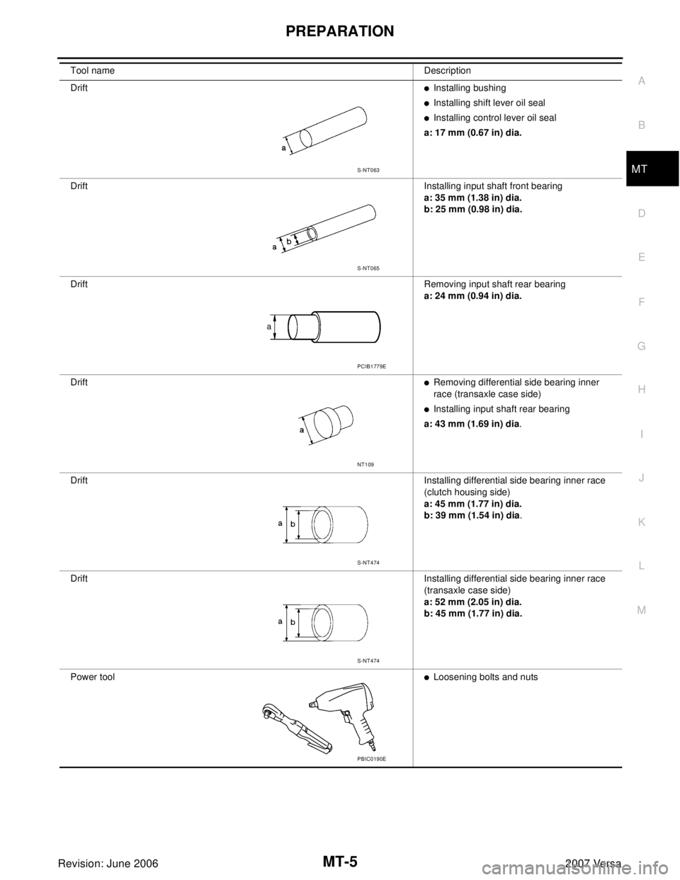
Drift�Installing bushing
�Installing shift lever oil seal
�Installing control lever oil seal
a: 17 mm (0.67 in) dia.
DriftInstalling input shaft front bearing
a: 35 mm (1.38 in) dia.
b: 25 mm (0.98 in) dia.
DriftRemoving input shaft rear bearing
a: 24 mm (0.94 in) dia.
Drift
�Removing differential side bearing inner
race (transaxle case side)
�Installing input shaft rear bearing
a: 43 mm (1.69 in) dia.
DriftInstalling differential side bearing inner race
(clutch housing side)
a: 45 mm (1.77 in) dia.
b: 39 mm (1.54 in) dia.
DriftInstalling differential side bearing inner race
(transaxle case side)
a: 52 mm (2.05 in) dia.
b: 45 mm (1.77 in) dia.
Power tool
�Loosening bolts and nuts Tool nameDescription
S-NT063
S-NT065
PCIB1779E
NT109
S-NT474
S-NT474
PBIC0190E
Page 2369 of 2896
DESCRIPTION
MT-7
D
E
F
G
H
I
J
K
L
MA
B
MT
Revision: June 20062007 Versa
DESCRIPTIONPFP:00000
Cross-Sectional ViewUCS0065I
1. Clutch housing 2. CSC (Concentric Slave Cylinder) 3. Reverse idler shaft
4. Reverse input gear 5. Reverse output gear 6. 2nd input gear
7. 3rd input gear 8. 3rd-4th synchronizer assembly 9. 4th input gear
10. 5th input gear 11. 5th-6th synchronizer assembly 12. 6th input gear
13. Transaxle case 14. 6th main gear 15. 5th main gear
16. 4th main gear 17. 3rd main gear 18. 2nd main gear
19. 1st-2nd synchronizer assembly 20. 1st main gear 21. Differential assembly
22. Final gear 23. Mainshaft 24. Input shaft
SCIA7618E
Page 2372 of 2896
MT-10
SIDE OIL SEAL
Revision: June 20062007 Versa
SIDE OIL SEALPFP:32113
Removal and InstallationUCS005LK
REMOVAL
1. Remove front drive shafts from transaxle assembly. Refer to FAX-8, "Removal and Installation (Left Side)"
.
2. Remove differential side oil seal (1) using a suitable tool.
CAUTION:
Be careful not to damage transaxle case and clutch hous-
ing.
INSTALLATION
1. Install differential side oil seal (1) to clutch housing and transaxle
case using Tool (A).
2. Installation is in the reverse order of removal. Check oil level
after installation. Refer to MT-9, "
Checking M/T Oil" .
CAUTION:
Do not reuse oil seal.
SCIA7625E
Tool number A: ST38100300 (J-25523)
SCIA7626E
Page 2374 of 2896
MT-12
CONTROL LINKAGE
Revision: June 20062007 Versa
CONTROL LINKAGEPFP:34103
Components of Control Device and CableUCS005LM
Removal and InstallationUCS005LN
REMOVAL
1. Remove battery. Refer to SC-9, "Removal and Installation" .
2. Remove air duct (Inlet), air duct and air cleaner case. Refer to EM-16, "
Removal and Installation" .
3. Remove shift cable from shift lever.
4. Remove select cable according to the following.
a. Move stopper (1) to the unlocked position.
1. Control lever knob 2. Control lever 3. Control device assembly
4. Select cable 5. Shift cable 6. Lock plate
7. Clutch housing 8. Cable bracket 9. Tapping bolt
10. Cable support bracket 11. Adapter plate
WCIA0626E
SCIA7842E
Page 2375 of 2896
 of select cable (2) and then remove it
from select lever (3).
5. Shift control lever to neu")
CONTROL LINKAGE
MT-13
D
E
F
G
H
I
J
K
L
MA
B
MT
Revision: June 20062007 Versa
b. Pull the release button (1) of select cable (2) and then remove it
from select lever (3).
5. Shift control lever to neutral position.
6. Remove control lever knob.
7. Remove center console assembly. Refer to IP-22, "
CENTER
CONSOLE ASSEMBLY" .
8. Remove control device assembly bolts.
9. Remove exhaust front tube, center muffler and heat plate. Refer
to EX-4, "
Removal and Installation" .
10. Remove cable support bracket.
11. Remove select cable and shift cable from cable bracket.
12. Remove control device assembly from the vehicle.
INSTALLATION
Installation is in the reverse order of removal.
NOTE:
Self tapping bolts are used to attach cables to the clutch housing.
�Securely assemble each cable and lever of control shaft.
�Be careful about the installation direction, and push control lever
knob onto control lever.
CAUTION:
Do not reuse control lever knob.
�Make sure that the front/rear claws (1) of control device assem-
bly are in contact with flange of the floor (2).
�When control lever is selected to 1st-2nd side and 5th-6th side,
confirm control lever returns to neutral position smoothly.
�When control lever is shifted to each position, make sure there
is no binding or disconnection in each boot.
�Move stopper (1) to lock position when installing the shift cable
onto the shift lever.
WCIA0606E
SCIA7630E
PCIB1510E
SCIA7846E
Page 2377 of 2896

TRANSAXLE ASSEMBLY
MT-15
D
E
F
G
H
I
J
K
L
MA
B
MT
Revision: June 20062007 Versa
TRANSAXLE ASSEMBLYPFP:32010
Removal and InstallationUCS005LQ
CAUTION:
If transaxle assembly is removed from the vehicle, always replace CSC (Concentric Slave Cylinder).
Inserted CSC returns to the original position when removing transaxle assembly. Dust on clutch disc
sliding parts may damage CSC seal, and may cause clutch fluid leakage.
COMPONENTS
REMOVAL
1. Drain gear oil. Refer to MT-9, "Changing M/T Oil" .
2. Drain clutch fluid and remove clutch tube from CSC. Refer to CL-9, "
Removal and Installation" .
CAUTION:
Do not depress clutch pedal during removal procedure.
3. Remove engine and transaxle assembly. Refer to EM-73, "
Removal and Installation" .
4. Remove starter motor. Refer to SC-23, "
Removal and Installation" .
5. Remove transaxle assembly to engine bolts.
6. Separate transaxle assembly from engine.
INSTALLATION
Installation is in the reverse order of removal.
1. LH engine mount bracket (transaxle
side)2. Transaxle assembly 3. Rear engine mount bracket
4. Washer 5. Rear torque rod⇐Front
: Refer to MT-15, "
INSTALLATION" for specification.
SCIA7631E
 3. Reverse idler shaft
4")

