Page 2427 of 2896
PREPARATION
MTC-15
C
D
E
F
G
H
I
K
L
MA
B
MTC
Revision: June 20062007 Versa
Commercial Service ToolsEJS00590
(Kent-Moore No.)
Tool nameDescription
(J-41810-NI)
Refrigerant identifier equipment (R-
134a)For checking refrigerant purity and
system contamination
Power toolLoosening bolts and nuts
(J-44614)
Clutch disc holding toolClutch disc holding tool
RJIA0197E
PBIC0190E
WHA230
Page 2436 of 2896
MTC-24
TROUBLE DIAGNOSIS
Revision: June 20062007 Versa
TROUBLE DIAGNOSISPFP:00004
CONSULT-II Function (BCM)EJS0057E
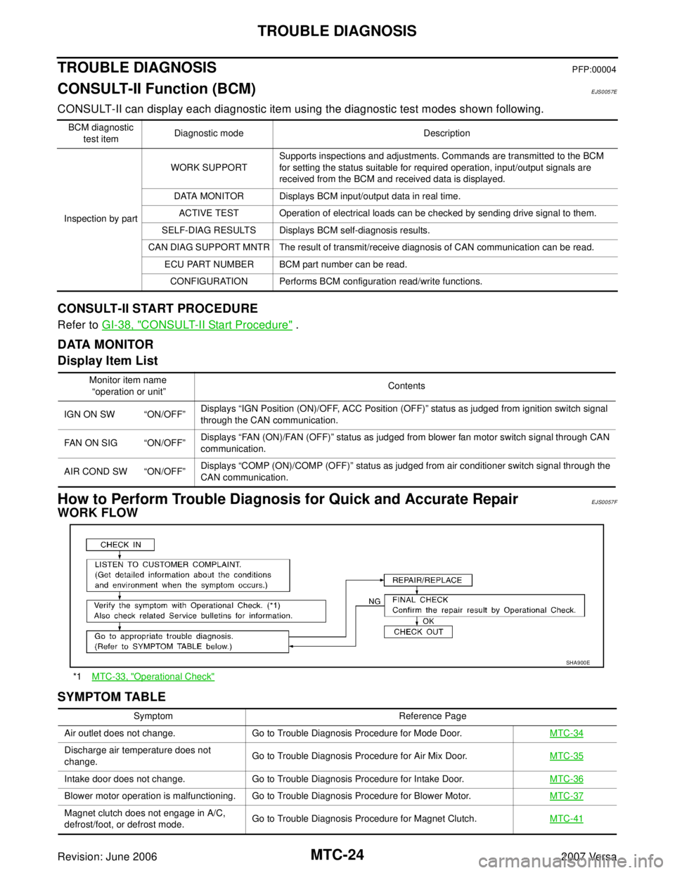
CONSULT-II can display each diagnostic item using the diagnostic test modes shown following.
CONSULT-II START PROCEDURE
Refer to GI-38, "CONSULT-II Start Procedure" .
DATA MONITOR
Display Item List
How to Perform Trouble Diagnosis for Quick and Accurate RepairEJS0057F
WORK FLOW
SYMPTOM TABLE
BCM diagnostic
test itemDiagnostic mode Description
Inspection by partWORK SUPPORTSupports inspections and adjustments. Commands are transmitted to the BCM
for setting the status suitable for required operation, input/output signals are
received from the BCM and received data is displayed.
DATA MONITOR Displays BCM input/output data in real time.
ACTIVE TEST Operation of electrical loads can be checked by sending drive signal to them.
SELF-DIAG RESULTS Displays BCM self-diagnosis results.
CAN DIAG SUPPORT MNTR The result of transmit/receive diagnosis of CAN communication can be read.
ECU PART NUMBER BCM part number can be read.
CONFIGURATION Performs BCM configuration read/write functions.
Monitor item name
“operation or unit”Contents
IGN ON SW “ON/OFF”Displays “IGN Position (ON)/OFF, ACC Position (OFF)” status as judged from ignition switch signal
through the CAN communication.
FAN ON SIG “ON/OFF”Displays “FAN (ON)/FAN (OFF)” status as judged from blower fan motor switch signal through CAN
communication.
AIR COND SW “ON/OFF”Displays “COMP (ON)/COMP (OFF)” status as judged from air conditioner switch signal through the
CAN communication.
*1MTC-33, "Operational Check"
SHA9 00 E
Symptom Reference Page
Air outlet does not change. Go to Trouble Diagnosis Procedure for Mode Door.MTC-34
Discharge air temperature does not
change.Go to Trouble Diagnosis Procedure for Air Mix Door.MTC-35
Intake door does not change. Go to Trouble Diagnosis Procedure for Intake Door.MTC-36
Blower motor operation is malfunctioning. Go to Trouble Diagnosis Procedure for Blower Motor.MTC-37
Magnet clutch does not engage in A/C,
defrost/foot, or defrost mode.Go to Trouble Diagnosis Procedure for Magnet Clutch.MTC-41
Page 2445 of 2896
TROUBLE DIAGNOSIS
MTC-33
C
D
E
F
G
H
I
K
L
MA
B
MTC
Revision: June 20062007 Versa
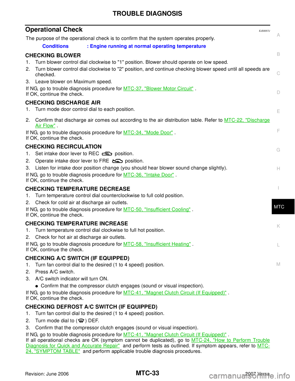
Operational CheckEJS0057J
The purpose of the operational check is to confirm that the system operates properly.
CHECKING BLOWER
1. Turn blower control dial clockwise to "1" position. Blower should operate on low speed.
2. Turn blower control dial clockwise to "2" position, and continue checking blower speed until all speeds are
checked.
3. Leave blower on Maximum speed.
If NG, go to trouble diagnosis procedure for MTC-37, "
Blower Motor Circuit" .
If OK, continue the check.
CHECKING DISCHARGE AIR
1. Turn mode door control dial to each position.
2. Confirm that discharge air comes out according to the air distribution table. Refer to MTC-22, "
Discharge
Air Flow" .
If NG, go to trouble diagnosis procedure for MTC-34, "
Mode Door" .
If OK, continue the check.
CHECKING RECIRCULATION
1. Set intake door lever to REC position.
2. Operate intake door lever to FRE position.
3. Listen for intake door position change (you should hear blower sound change slightly).
If NG, go to trouble diagnosis procedure for MTC-36, "
Intake Door" .
If OK, continue the check.
CHECKING TEMPERATURE DECREASE
1. Turn temperature control dial counterclockwise to full cold position.
2. Check for cold air at discharge air outlets.
If NG, go to trouble diagnosis procedure for MTC-50, "
Insufficient Cooling" .
If OK, continue the check.
CHECKING TEMPERATURE INCREASE
1. Turn temperature control dial clockwise to full hot position.
2. Check for hot air at discharge air outlets.
If NG, go to trouble diagnosis procedure for MTC-58, "
Insufficient Heating" .
If OK, continue the check.
CHECKING A/C SWITCH (IF EQUIPPED)
1. Turn fan control dial to the desired (1 to 4 speed) position.
2. Press A/C switch.
3. A/C switch indicator will turn ON.
�Confirm that the compressor clutch engages (sound or visual inspection).
If NG, go to trouble diagnosis procedure for MTC-41, "
Magnet Clutch Circuit (If Equipped)" .
If OK, continue the check.
CHECKING DEFROST A/C SWITCH (IF EQUIPPED)
1. Turn fan control dial to the desired (1 to 4 speed) position.
2. Turn mode dial to ( ) DEF.
3. Confirm that the compressor clutch engages (sound or visual inspection).
If NG, go to trouble diagnosis procedure for MTC-41, "
Magnet Clutch Circuit (If Equipped)" .
If all operational checks are OK (symptom cannot be duplicated), go to MTC-24, "
How to Perform Trouble
Diagnosis for Quick and Accurate Repair" and perform tests as outlined. If symptom appears, refer to MTC-
24, "SYMPTOM TABLE" and perform applicable trouble diagnosis procedures. Conditions : Engine running at normal operating temperature
Page 2446 of 2896
MTC-34
TROUBLE DIAGNOSIS
Revision: June 20062007 Versa
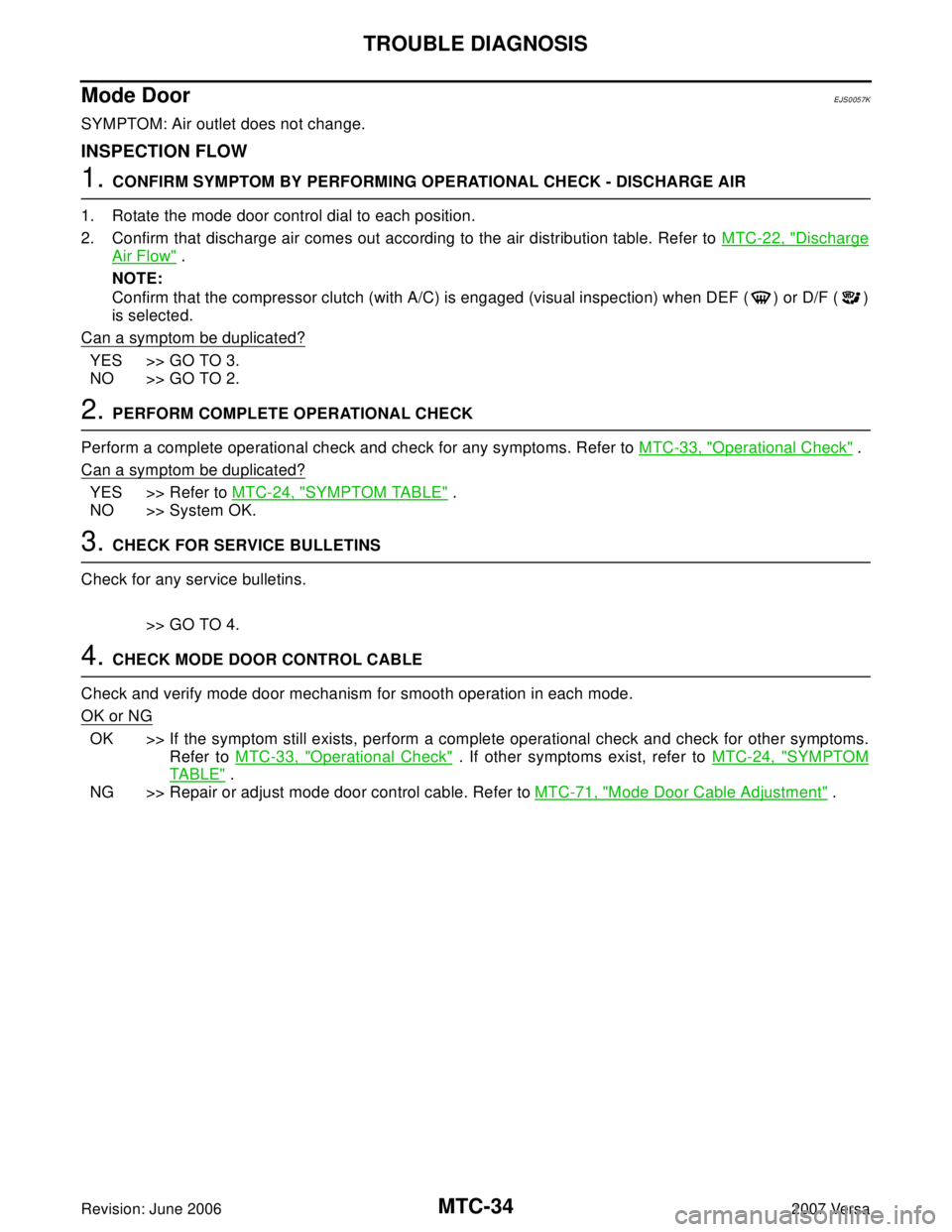
Mode DoorEJS0057K
SYMPTOM: Air outlet does not change.
INSPECTION FLOW
1. CONFIRM SYMPTOM BY PERFORMING OPERATIONAL CHECK - DISCHARGE AIR
1. Rotate the mode door control dial to each position.
2. Confirm that discharge air comes out according to the air distribution table. Refer to MTC-22, "
Discharge
Air Flow" .
NOTE:
Confirm that the compressor clutch (with A/C) is engaged (visual inspection) when DEF ( ) or D/F ( )
is selected.
Can a symptom be duplicated?
YES >> GO TO 3.
NO >> GO TO 2.
2. PERFORM COMPLETE OPERATIONAL CHECK
Perform a complete operational check and check for any symptoms. Refer to MTC-33, "
Operational Check" .
Can a symptom be duplicated?
YES >> Refer to MTC-24, "SYMPTOM TABLE" .
NO >> System OK.
3. CHECK FOR SERVICE BULLETINS
Check for any service bulletins.
>> GO TO 4.
4. CHECK MODE DOOR CONTROL CABLE
Check and verify mode door mechanism for smooth operation in each mode.
OK or NG
OK >> If the symptom still exists, perform a complete operational check and check for other symptoms.
Refer to MTC-33, "
Operational Check" . If other symptoms exist, refer to MTC-24, "SYMPTOM
TABLE" .
NG >> Repair or adjust mode door control cable. Refer to MTC-71, "
Mode Door Cable Adjustment" .
Page 2453 of 2896
TROUBLE DIAGNOSIS
MTC-41
C
D
E
F
G
H
I
K
L
MA
B
MTC
Revision: June 20062007 Versa
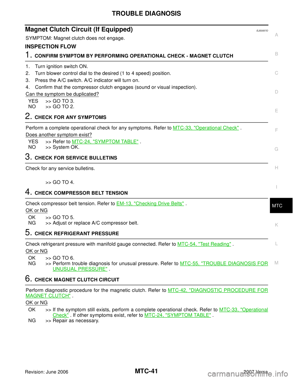
Magnet Clutch Circuit (If Equipped)EJS0057O
SYMPTOM: Magnet clutch does not engage.
INSPECTION FLOW
1. CONFIRM SYMPTOM BY PERFORMING OPERATIONAL CHECK - MAGNET CLUTCH
1. Turn ignition switch ON.
2. Turn blower control dial to the desired (1 to 4 speed) position.
3. Press the A/C switch. A/C indicator will turn on.
4. Confirm that the compressor clutch engages (sound or visual inspection).
Can the symptom be duplicated?
YES >> GO TO 3.
NO >> GO TO 2.
2. CHECK FOR ANY SYMPTOMS
Perform a complete operational check for any symptoms. Refer to MTC-33, "
Operational Check" .
Does another symptom exist?
YES >> Refer to MTC-24, "SYMPTOM TABLE" .
NO >> System OK.
3. CHECK FOR SERVICE BULLETINS
Check for any service bulletins.
>> GO TO 4.
4. CHECK COMPRESSOR BELT TENSION
Check compressor belt tension. Refer to EM-13, "
Checking Drive Belts" .
OK or NG
OK >> GO TO 5.
NG >> Adjust or replace A/C compressor belt.
5. CHECK REFRIGERANT PRESSURE
Check refrigerant pressure with manifold gauge connected. Refer to MTC-54, "
Test Reading" .
OK or NG
OK >> GO TO 6.
NG >> Perform trouble diagnosis for unusual pressure. Refer to MTC-55, "
TROUBLE DIAGNOSIS FOR
UNUSUAL PRESSURE" .
6. CHECK MAGNET CLUTCH CIRCUIT
Perform diagnostic procedure for the magnetic clutch. Refer to MTC-42, "
DIAGNOSTIC PROCEDURE FOR
MAGNET CLUTCH" .
OK or NG
OK >> If the symptom still exists, perform a complete operational check. Refer to MTC-33, "Operational
Check" . If other symptoms exist, refer to MTC-24, "SYMPTOM TABLE" .
NG >> Repair as necessary.
Page 2454 of 2896
MTC-42
TROUBLE DIAGNOSIS
Revision: June 20062007 Versa
SYSTEM DESCRIPTION
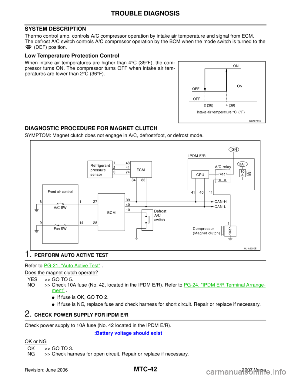
Thermo control amp. controls A/C compressor operation by intake air temperature and signal from ECM.
The defrost A/C switch controls A/C compressor operation by the BCM when the mode switch is turned to the
(DEF) position.
Low Temperature Protection Control
When intake air temperatures are higher than 4°C (39°F), the com-
pressor turns ON. The compressor turns OFF when intake air tem-
peratures are lower than 2°C (36°F).
DIAGNOSTIC PROCEDURE FOR MAGNET CLUTCH
SYMPTOM: Magnet clutch does not engage in A/C, defrost/foot, or defrost mode.
1. PERFORM AUTO ACTIVE TEST
Refer to PG-21, "
Auto Active Test" .
Does the magnet clutch operate?
YES >> GO TO 5.
NO >> Check 10A fuse (No. 42, located in the IPDM E/R). Refer to PG-24, "
IPDM E/R Terminal Arrange-
ment" .
�If fuse is OK, GO TO 2.
�If fuse is NG, replace fuse and check harness for short circuit. Repair or replace if necessary.
2. CHECK POWER SUPPLY FOR IPDM E/R
Check power supply to 10A fuse (No. 42 located in the IPDM E/R).
OK or NG
OK >> GO TO 3.
NG >> Check harness for open circuit. Repair or replace if necessary.
SJIA0741E
WJIA2250E
:Battery voltage should exist
Page 2455 of 2896
TROUBLE DIAGNOSIS
MTC-43
C
D
E
F
G
H
I
K
L
MA
B
MTC
Revision: June 20062007 Versa
3. CHECK POWER SUPPLY FOR A/C COMPRESSOR
1. Disconnect A/C compressor connector.
2. Start the engine.
3. Turn blower control dial and A/C switch ON.
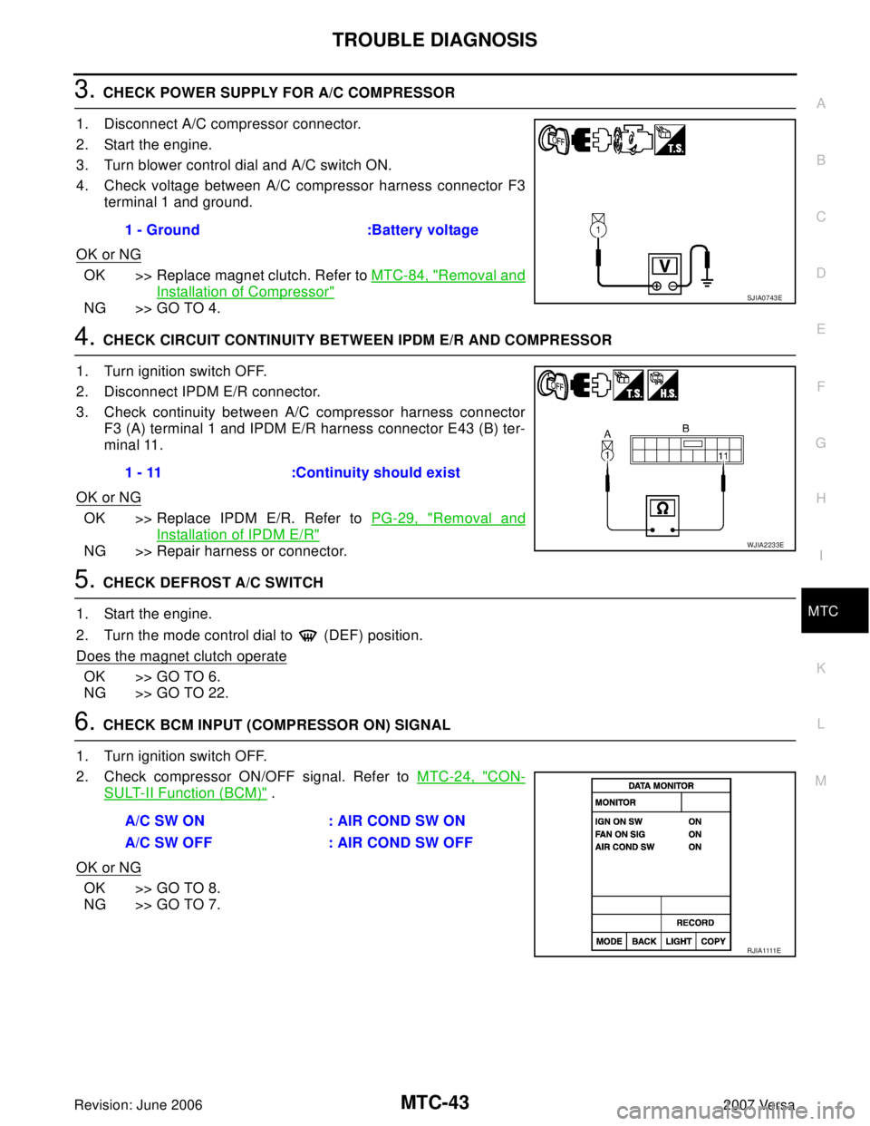
4. Check voltage between A/C compressor harness connector F3
terminal 1 and ground.
OK or NG
OK >> Replace magnet clutch. Refer to MTC-84, "Removal and
Installation of Compressor"
NG >> GO TO 4.
4. CHECK CIRCUIT CONTINUITY BETWEEN IPDM E/R AND COMPRESSOR
1. Turn ignition switch OFF.
2. Disconnect IPDM E/R connector.
3. Check continuity between A/C compressor harness connector
F3 (A) terminal 1 and IPDM E/R harness connector E43 (B) ter-
minal 11.
OK or NG
OK >> Replace IPDM E/R. Refer to PG-29, "Removal and
Installation of IPDM E/R"
NG >> Repair harness or connector.
5. CHECK DEFROST A/C SWITCH
1. Start the engine.
2. Turn the mode control dial to (DEF) position.
Does the magnet clutch operate
OK >> GO TO 6.
NG >> GO TO 22.
6. CHECK BCM INPUT (COMPRESSOR ON) SIGNAL
1. Turn ignition switch OFF.
2. Check compressor ON/OFF signal. Refer to MTC-24, "
CON-
SULT-II Function (BCM)" .
OK or NG
OK >> GO TO 8.
NG >> GO TO 7.1 - Ground :Battery voltage
SJIA0743E
1 - 11 :Continuity should exist
WJIA2233E
A/C SW ON : AIR COND SW ON
A/C SW OFF : AIR COND SW OFF
R J I A 1111E
Page 2465 of 2896
TROUBLE DIAGNOSIS
MTC-53
C
D
E
F
G
H
I
K
L
MA
B
MTC
Revision: June 20062007 Versa
*1MTC-85, "INSPECTION FOR
CLUTCH DISC TO PULLEY CLEAR-
ANCE"
*2MTC-37, "Blower Motor Circuit"*3EM-13, "Checking Drive Belts"
RJIA3107E