Page 1089 of 2896
CVT-192
SHIFT CONTROL SYSTEM
Revision: June 20062007 Versa
CONTROL CABLE COMPONENTS
Refer to the figure below for control cable removal and installation procedure.
REMOVAL
CAUTION:
Make sure that parking brake is applied before removal and installation.
1. Place the selector lever in the “N” position.
2. Remove the center console assembly. Refer to IP-10, "
INSTRUMENT PANEL ASSEMBLY" .
3. Disconnect the CVT device harness connector (1).
4. Remove the key interlock cable from the control device assem-
bly. Refer to CVT-202, "
Removal and Installation" .
5. Remove the bolts (A) from the control device assembly (1).
6. Remove exhaust front tube, center muffler and heat plates.
Refer to EM-21, "
EXHAUST MANIFOLD" .
1. Selector lever knob 2. Control device assembly 3. Lock plate
4. Bracket 5. Control cable 6. Bracket
7. Lock plate 8. Bracket 9. Transaxle assembly
A. Floor
WCIA0639E
SCIA6965E
WCIA0609E
Page 1092 of 2896

SHIFT CONTROL SYSTEM
CVT-195
D
E
F
G
H
I
J
K
L
MA
B
CVT
Revision: June 20062007 Versa
Selector Lever Knob Removal and InstallationUCS006XQ
REMOVAL
CAUTION:
Make sure that parking brake is applied before removal/installation.
1. Set selector lever knob (1) in “N” position.
2. Slide knob cover (2) downward.
3. Pull out lock pin (3) from selector lever knob (1).
4. Remove selector lever knob (1) and knob cover (2) as a set from
selector lever.
CAUTION:
Do not push selector button.
INSTALLATION
1. Insert lock pin (1) to selector lever knob (2).
2. Install knob cover (3) to selector lever knob (2).
3. Set selector lever in “N” position.
4. Install selector lever knob over selector lever until a click is felt.
CAUTION:
�Do not tilt selector lever knob when installing. Install it
straight, and do not tap or apply any shock to install it.
�Do not push selector button.
Adjustment of CVT PositionUCS0064J
CAUTION:
Make sure that parking brake is applied before adjustment.
1. Loosen the control cable nut (A) and place the manual lever (1)
in “P” position.
2. Place selector lever in “P” position.
3. Push the control cable (2) in with a load of 9.8 N (approximately
1 kg, 2.2 lb). Release the control cable and temporarily tighten
the control cable nut.
NOTE:
Do not move the manual lever. Make sure the manual lever
stays in the “P” position.
4. Tighten the control cable nut.
CAUTION:
Secure the manual lever when tightening nut.
5. Check the operation of the CVT. Refer to CVT-196, "
Checking of CVT Position" .
SCIA6971E
SCIA6972E
Control cable nut: Refer to CVT-192, "CON-
TROL CABLE COMPO-
NENTS" .
WCIA0608E
Page 1093 of 2896

2. Make sur")
CVT-196
SHIFT CONTROL SYSTEM
Revision: June 20062007 Versa
Checking of CVT PositionUCS0064K
1. Place selector lever in “P” position, and turn ignition switch ON. (Do not start engine.)
2. Make sure selector lever can be shifted to other than “P” position when brake pedal is depressed. Also
make sure selector lever can be shifted from “P” position only when brake pedal is depressed.
3. Move the selector lever and check for excessive effort, sticking, noise or rattle.
4. Confirm the selector lever stops at each position with the feel of engagement when it is moved through all
the positions. Check that the actual position of the selector lever matches the position shown by the shift
position indicator and the manual lever on the transaxle.
5. The method of operating the selector lever to individual posi-
tions correctly should be as shown.
�(A): Press selector button to operate selector lever, while
depressing the brake pedal.
�(B): Press selector button to operate selector lever.
�(C): Selector lever can be operated without pressing selector
button.
6. Confirm the back-up lamps illuminate only when selector lever is
placed in the “R” position. Confirm the back-up lamps do not illu-
minate when the selector lever is pushed toward the “R” position
side with the gear position remained in the “P” or “N” position.
7. Confirm the engine can only be started with the selector lever in the “P” and “N” positions.
8. Make sure transaxle is locked completely in “P” position.
WCIA0620E
Page 1094 of 2896
CVT SHIFT LOCK SYSTEM
CVT-197
D
E
F
G
H
I
J
K
L
MA
B
CVT
Revision: June 20062007 Versa
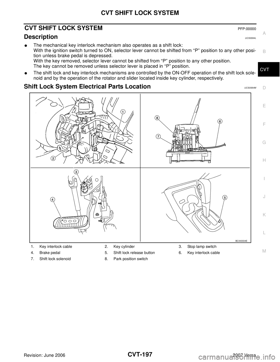
CVT SHIFT LOCK SYSTEMPFP:00000
DescriptionUCS0064L
�The mechanical key interlock mechanism also operates as a shift lock:
With the ignition switch turned to ON, selector lever cannot be shifted from “P” position to any other posi-
tion unless brake pedal is depressed.
With the key removed, selector lever cannot be shifted from “P” position to any other position.
The key cannot be removed unless selector lever is placed in “P” position.
�The shift lock and key interlock mechanisms are controlled by the ON-OFF operation of the shift lock sole-
noid and by the operation of the rotator and slider located inside key cylinder, respectively.
Shift Lock System Electrical Parts LocationUCS0064M
1. Key interlock cable 2. Key cylinder 3. Stop lamp switch
4. Brake pedal 5. Shift lock release button 6. Key interlock cable
7. Shift lock solenoid 8. Park position switch
BCIA0034E
Page 1096 of 2896

CVT SHIFT LOCK SYSTEM
CVT-199
D
E
F
G
H
I
J
K
L
MA
B
CVT
Revision: June 20062007 Versa
Diagnostic ProcedureUCS006KN
SYMPTOM 1:
�Selector lever cannot be moved from “P” position with ignition switch in ON position and brake
pedal depressed.
�Selector lever can be moved from “P” position with ignition key in ON position and brake pedal
released.
�Selector lever can be moved from “P” position when ignition switch is removed from key cylinder.
SYMPTOM 2:
�Ignition key cannot be removed when selector lever is set to “P” position.
�Ignition key can be removed when selector lever is set to any position except “P” position.
1. CHECK KEY INTERLOCK CABLE
Check key interlock cable for damage.
OK or NG
OK >> GO TO 2.
NG >> Repair key interlock cable. Refer to AT-239, "
Removal and Installation" .
2. CHECK CVT POSITION
Check CVT position. Refer to CVT-196, "
Checking of CVT Position" .
OK or NG
OK >> GO TO 3.
NG >> Adjust control cable. Refer to CVT-195, "
Adjustment of CVT Position" .
3. CHECK SHIFT LOCK SOLENOID AND PARK POSITION SWITCH
1. Turn ignition switch ON. (Do not start engine.)
2. Selector lever is set in “P” position.
3. Check operation sound.
OK or NG
OK >>INSPECTION END
NG - 1 >> With intelligent key: GO TO 4.
NG - 2 >> Without intelligent key: GO TO 5.
4. CHECK POWER SOURCE
1. Turn ignition switch ON. (Do not start engine.)
2. Check voltage between CVT device harness connector terminal
5 and ground.
OK or NG
OK >> GO TO 8.
NG >> GO TO 6.
Condition Brake pedal Operation sound
When ignition switch is turned to ON position and selector lever is set in
“P” position.Depressed Yes
Released No
Voltage:
Brake pedal depressed: Battery voltage
Brake pedal released: 0V
SCIA7934E
Page 1097 of 2896

2. Check voltage between CVT device harness connector terminal
5 an")
CVT-200
CVT SHIFT LOCK SYSTEM
Revision: June 20062007 Versa
5. CHECK POWER SOURCE
1. Turn ignition switch ON. (Do not start engine.)
2. Check voltage between CVT device harness connector terminal
5 and ground.
OK or NG
OK >> GO TO 9.
NG >> GO TO 6.
6. CHECK STOP LAMP SWITCH
1. Turn ignition switch OFF.
2. Disconnect stop lamp switch harness connector.
3. Check continuity between stop lamp switch harness connector
terminals 3 and 4.
Check stop lamp switch after adjusting brake pedal. Refer to
BR-6, "
BRAKE PEDAL" .
OK or NG
OK >> GO TO 7.
NG >> Repair or replace damaged parts.
7. DETECT MALFUNCTIONING ITEM
Check the following. If any items are damaged, repair or replace damaged parts.
�Harness for short or open between ignition switch and stop lamp switch harness connector
�Harness for short or open between stop lamp switch harness connector and CVT device harness connec-
tor
�10A fuse [No.3, located in the fuse block (J/B)]
�Ignition switch, Refer to PG-4, "POWER SUPPLY ROUTING CIRCUIT" .
OK or NG
OK >>INSPECTION END
NG >> Repair or replace damaged parts. Voltage:
Brake pedal depressed: Battery voltage
Brake pedal released: 0V
SCIA7935E
Condition Continuity
When brake pedal is depressed Yes
When brake pedal is released No
SCIA2126E
Page 1099 of 2896
CVT-202
KEY INTERLOCK CABLE
Revision: June 20062007 Versa
KEY INTERLOCK CABLEPFP:34908
Removal and InstallationUCS006XR
COMPONENTS
REMOVAL
Refer to the figure for key interlock cable removal procedure.
CAUTION:
Make sure that parking brake is applied before removal/installation.
1. Place the selector lever in the “N” position.
2. Remove the selector lever knob. Refer to CVT-195, "
Selector Lever Knob Removal and Installation" .
3. Remove the center console assembly. Refer to IP-10, "
INSTRUMENT PANEL ASSEMBLY" .
1. Key interlock cable 2. Key cylinder 3. Control device assembly
A. Lock plate B. Holder C. Clip
D. Slider E. Key interlock rod F. Adjust holder
G. Casing cap
WCIA0621E
Page 1120 of 2896

COMBINATION METERS
DI-11
C
D
E
F
G
H
I
J
L
MA
B
DI
Revision: June 20062007 Versa
Combination Meter Harness Connector Terminal LayoutEKS00IAQ
Terminals and Reference Value for Combination MeterEKS00I0A
LKIA0698E
Te r -
minal
No.Wire
colorItemCondition
Reference value (V)
(Approx.) Ignition
switchOperation or condition
1 L CAN-H — — —
2 P CAN-L — — —
3GVehicle speed signal output
(2-pulse)ONSpeedometer operated
[When vehicle speed is approx.
40 km/h (25 MPH)] NOTE:
Maximum voltage may be 5 V due to
specifications (connected units).
4SBVehicle speed signal output
(8-pulse)ONSpeedometer operated
[When vehicle speed is approx.
40 km/h (25 MPH)]NOTE:
Maximum voltage may be 12 V due to
specifications (connected units).
5WVehicle speed signal (without
ABS or CVT)ONSpeedometer operated
[When vehicle speed is approx.
20 km/h (12 MPH)]240 Hz
6 BR Fuel level sensor signal (+) — —Refer to DI-23, "
FUEL LEVEL SENSOR
UNIT CHECK" .
8 P O/D OFF switch ONO/D OFF switch pressed 0
O/D OFF switch released Battery voltage
9 Y Seat belt buckle switch LH ONUnfastened (ON) 0
Fastened (OFF) Battery voltage
10 SB Parking Brake switch ONParking brake applied 0
Parking brake released Battery voltage
11 LG Brake fluid level switch ONBrake fluid level low 0
Brake fluid level normal Battery voltage
12 BR Illumination control switch (+) — —Refer to LT-108, "
ILLUMINATION
OPERATION BY LIGHTING SWITCH" .
PKIC0642E
PKIC0643E