Page 2659 of 2896

COIL SPRING
RSU-11
C
D
F
G
H
I
J
K
L
MA
B
RSU
Revision: June 20062007 Versa
COIL SPRINGPFP:55020
Removal and InstallationEES002D1
REMOVAL
1. Remove rear tires from vehicle using power tool.
2. Remove wheel sensor from wheel hub and bearing assembly. Refer to BRC-33, "
WHEEL SENSORS" .
CAUTION:
Do not pull on wheel sensor harness.
3. Separate brake tube from wheel cylinder. Refer to BR-11, "
BRAKE TUBE AND HOSE" .
4. Set jack under rear suspension beam.
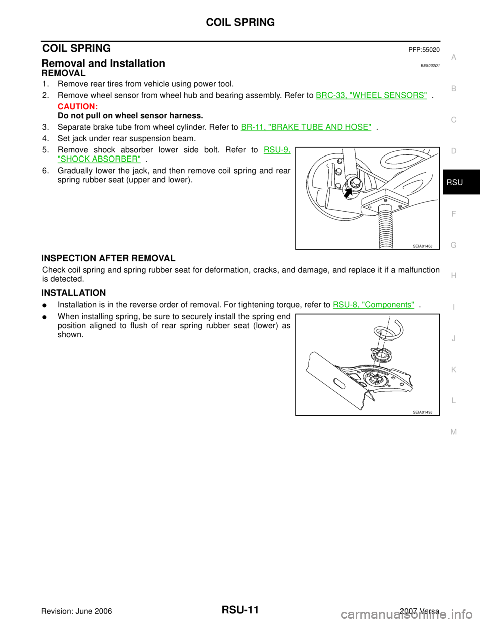
5. Remove shock absorber lower side bolt. Refer to RSU-9,
"SHOCK ABSORBER" .
6. Gradually lower the jack, and then remove coil spring and rear
spring rubber seat (upper and lower).
INSPECTION AFTER REMOVAL
Check coil spring and spring rubber seat for deformation, cracks, and damage, and replace it if a malfunction
is detected.
INSTALLATION
�Installation is in the reverse order of removal. For tightening torque, refer to RSU-8, "Components" .
�When installing spring, be sure to securely install the spring end
position aligned to flush of rear spring rubber seat (lower) as
shown.
SEIA0146J
SEIA0149J
Page 2660 of 2896

RSU-12
REAR SUSPENSION BEAM
Revision: June 20062007 Versa
REAR SUSPENSION BEAMPFP:55501
Removal and InstallationEES002D2
REMOVAL
1. Remove rear tires from vehicle using power tool.
2. Separate parking brake rear cable from rear drum brake and rear suspension beam. Refer to PB-4,
"PARKING BRAKE CONTROL" .
3. Remove wheel sensor and wheel sensor harness from wheel hub and bearing assembly and rear suspen-
sion beam. Refer to BRC-33, "
WHEEL SENSORS" .
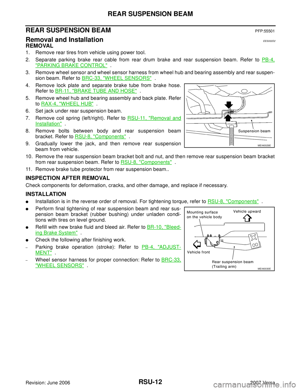
4. Remove lock plate and separate brake tube from brake hose.
Refer to BR-11, "
BRAKE TUBE AND HOSE" .
5. Remove wheel hub and bearing assembly and back plate. Refer
to RAX-4, "
WHEEL HUB" .
6. Set jack under rear suspension beam.
7. Remove coil spring (left/right). Refer to RSU-11, "
Removal and
Installation" .
8. Remove bolts between body and rear suspension beam
bracket. Refer to RSU-8, "
Components" .
9. Gradually lower the jack, and then remove rear suspension
beam from vehicle.
10. Remove the rear suspension beam bracket bolt and nut, and then remove rear suspension beam bracket
from rear suspension beam. Refer to RSU-8, "
Components" .
11. Remove brake tube protector from rear suspension beam..
INSPECTION AFTER REMOVAL
Check components for deformation, cracks, and other damage, and replace if necessary.
INSTALLATION
�Installation is in the reverse order of removal. For tightening torque, refer to RSU-8, "Components" .
�Perform final tightening of rear suspension beam and rear sus-
pension beam bracket (rubber bushing) under unladen condi-
tions with tires on level ground.
�Refill with new brake fluid and bleed air. Refer to BR-10, "Bleed-
ing Brake System" .
�Check the following after finishing work.
–Parking brake operation (stroke): Refer to PB-4, "ADJUST-
MENT" .
–Wheel sensor harness for proper connection: Refer to BRC-33,
"WHEEL SENSORS" .
MEIA0029E
MEIA0030E
Page 2671 of 2896

SEAT BELTS
SB-9
C
D
E
F
G
I
J
K
L
MA
B
SB
Revision: June 20062007 Versa
SEAT BELT RETRACTOR ON-VEHICLE CHECK
Emergency Locking Retractors (ELR) and Automatic Locking Retractors (ALR)
NOTE:
All seat belt retractors are of the Emergency Locking Retractors (ELR) type. In an emergency (sudden stop)
the retractor will lock and prevent the webbing from extending any further. All 3-point type seat belt retractors
except the driver's seat belt also have an Automatic Locking Retractors (ALR) mode. The ALR mode (also
called child restraint mode) is used when installing child seats. The ALR mode is activated when the seat belt
is fully extended. When the webbing is then retracted partially, the ALR mode automatically locks the seat belt
in a specific position so the webbing cannot be extended any further. To cancel the ALR mode, allow the seat
belt to fully wind back into the retractor.
Check the seat belt retractors using the following test(s) to determine if a retractor assembly is operating prop-
erly.
ELR Function Stationary Check
Grasp the shoulder webbing and pull it forward quickly. The retractor should lock and prevent the belt from
extending further.
ALR Function Stationary Check
1. Pull out entire length of seat belt from retractor until a click is heard.
2. Retract the webbing partially. A clicking noise should be heard as the webbing retracts, indicating that the
retractor is in the Automatic Locking Retractors (ALR) mode.
3. Grasp the seat belt and try to pull out the retractor. The webbing must lock and not extend any further. If
NG, replace the retractor assembly.
4. Allow the entire length of the webbing to retract to cancel the automatic locking mode.
ELR Function Moving Check
WA RN ING:
Perform the following test in a safe, open area clear of other vehicles and obstructions (for example, a
large, empty parking lot). Road surface must be paved and dry. DO NOT perform the following test on
wet or gravel roads or on public streets and highways. This could result in an accident and serious
personal injury. The driver and passenger must be prepared to brace themselves in the event the
retractor does not lock.
1. Fasten driver's seat belt. Buckle a passenger into the seat for the belt that is to be tested.
2. Proceed to the designated safe area.
3. Drive the vehicle at approximately 16 km/h (10 MPH). Notify any passengers of a pending sudden stop
and the driver and passenger must be prepared to brace themselves in the event the retractor does not
lock, apply brakes firmly and make a very hard stop.
During the stop, seat belts should lock and not be extended. If the seat belt retractor assembly does not lock,
perform the retractor off-vehicle check.
Page 2822 of 2896

WT-4
NOISE, VIBRATION AND HARSHNESS (NVH) TROUBLESHOOTING
Revision: June 20062007 Versa
NOISE, VIBRATION AND HARSHNESS (NVH) TROUBLESHOOTINGPFP:00003
NVH Troubleshooting ChartEES002D6
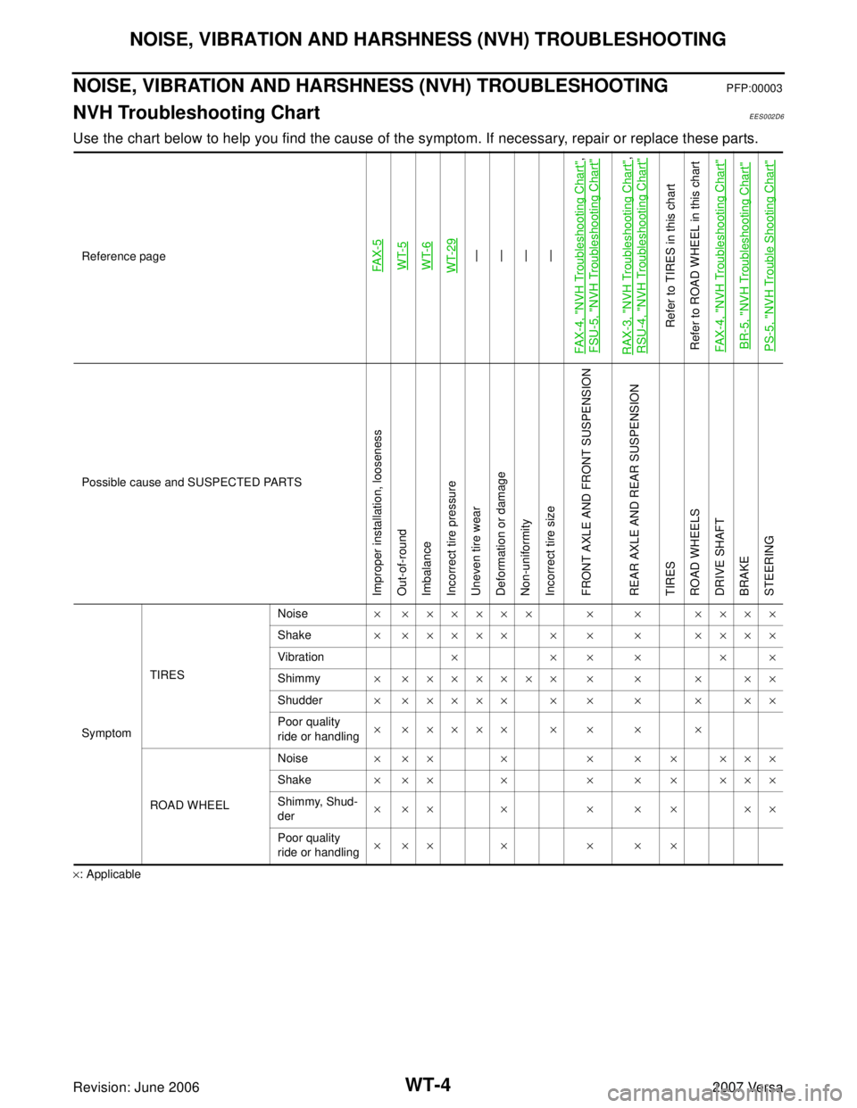
Use the chart below to help you find the cause of the symptom. If necessary, repair or replace these parts.
×: ApplicableReference page
FA X - 5WT-5
WT-6
WT-29—
—
—
—
FAX -4, "
NVH Troubleshooting Chart
",
FSU-5, "
NVH Troubleshooting Chart
"
RAX-3, "
NVH Troubleshooting Chart
",
RSU-4, "
NVH Troubleshooting Chart
"
Refer to TIRES in this chart
Refer to ROAD WHEEL in this chart
FAX -4, "
NVH Troubleshooting Chart
"
BR-5, "
NVH Troubleshooting Chart
"
PS-5, "
NVH Trouble Shooting Chart
"
Possible cause and SUSPECTED PARTS
Improper installation, looseness
Out-of-round
Imbalance
Incorrect tire pressure
Uneven tire wear
Deformation or damage
Non-uniformity
Incorrect tire size
FRONT AXLE AND FRONT SUSPENSION
REAR AXLE AND REAR SUSPENSION
TIRES
ROAD WHEELS
DRIVE SHAFT
BRAKE
STEERING
SymptomTIRESNoise× ×××××× × × ××××
Shake× ××××× × × × ××××
Vibration××××××
Shimmy× ××××××× × × × ××
Shudder× ××××× × × × × ××
Poor quality
ride or handling× ××××× × × × ×
ROAD WHEELNoise××× × × × × ×××
Shake××× × × × × ×××
Shimmy, Shud-
der×××× ×××××
Poor quality
ride or handling××× × × × ×