Page 2560 of 2896

PG-44
HARNESS
Revision: June 20062007 Versa
C4 E3 GR/4 : Cooling fan motor (without A/C) C3 E47 BR/8: IPDM E/R (Intelligent Power Distribu-
tion Module Engine Room)
C4 E3 B/2 : Cooling fan motor (with A/C) D3 E48 B/6: IPDM E/R (Intelligent Power Distribu-
tion Module Engine Room)
C4 E5 GR/3 : Resistor D1 E51 B/2 : Front wheel sensor LH
C3 E6 — : Fuse and fusible link box D3 E53 B/2: Front combination lamp LH
(parking)
B1 E7 SMJ : To M69
D3 E8 SMJ : To F8
B4 E9 BR/2 : Fusible link box (battery)
B3 E10 GR/2 : Fusible link box (battery)
B1 E11 B/2 : To M78
A3 E12 B/6 : Accelerator pedal position sensor
A2 E13 B/2 : Stop lamp switch (with M/T)
A2 E13 W/4 : Stop lamp switch (without M/T)
D3 E14 — : Engine ground (crash zone sensor)
C2 E15 — : Engine ground
B2 E16 B/32 : ECM
C5 E18 B/1 : Horn (low)
C4 E19 GR/6 : To F33
D5 E20 B/1 : Horn (low)
D3 E25 B/3: Front combination lamp LH
(headlamp)
E4 E27 B/2 : Front fog lamp LH
D4 E29 B/2: Front combination lamp LH
(turn signal)
B1 E31 W/24 : TCM
B1 E32 GR/24 : TCM
A2 E34 BR/2 : Clutch interlock switch (with M/T)
A2 E35 BR/2 : ASCD clutch switch
A2 E36 BR/2 : ASCD brake switch
B4 E40 GR/2 : Brake fluid level switch
D3 E42 B/2: IPDM E/R (Intelligent Power Distribu-
tion Module Engine Room)
C3 E43 W/16: IPDM E/R (Intelligent Power Distribu-
tion Module Engine Room)
C3 E44 W/6: IPDM E/R (Intelligent Power Distribu-
tion Module Engine Room)
D3 E45 BR/12: IPDM E/R (Intelligent Power Distribu-
tion Module Engine Room)
D3 E46 W/12: IPDM E/R (Intelligent Power Distribu-
tion Module Engine Room)
Page 2577 of 2896

HARNESS
PG-61
C
D
E
F
G
H
I
J
L
MA
B
PG
Revision: June 20062007 Versa
Wiring Diagram Codes (Cell Codes)EKS00IW9
Use the chart below to find out what each wiring diagram code stands for.
Refer to the wiring diagram code in the alphabetical index to find the location (page number) of each wiring
diagram.
Code Section Wiring Diagram Name
ABS BRC Anti-lock Brake System
A/C,M MTC Manual Air Conditioner
APPS1 EC Accelerator Pedal Position Sensor
A/F EC Air Fuel Ratio Sensor 1
A/FH EC Air Fuel Ratio Sensor 1 Heater
APPS2 EC Accelerator Pedal Position Sensor
APPS3 EC Accelerator Pedal Position Sensor
ASC/BS EC ASCD Brake Switch
ASC/SW EC ASCD Steering Switch
ASCBOF EC ASCD Brake Switch
ASCIND EC ASCD Indicator
AT/IND DI A/T Indicator Lamp
AUDIO AV Audio
BACK/L LT Back-up Lamp
BA/FTS AT A/T Fluid Temperature Sensor and TCM Power Supply
BRK/SW EC Brake Switch
CAN AT CAN Communication Line
CAN CVT CAN Communication Line
CAN EC CAN Communication Line
CAN LAN CAN System
CHARGE SC Charging System
CHIME DI Warning Chime
COOL/F EC Cooling Fan Control
COMBSW LT Combination Switch
CVTIND DI CVT Indicator Lamp
D/LOCK BL Power Door Lock
DEF GW Rear Window Defogger
DTRL LT Headlamp - With Daytime Light System
ECTS EC Engine Coolant Temperature Sensor
ENGSS AT Engine Speed Signal
EPS STC Electronic Controlled Power Steering
ETC1 EC Electric Throttle Control Function
ETC2 EC Throttle Control Motor Relay
ETC3 EC Throttle Control Motor
F/FOG LT Front Fog Lamp
F/PUMP EC Fuel Pump
FTS AT A/T Fluid Temperature Sensor
FTS CVT CVT Fluid Temperature Sensor Circuit
FTTS EC Fuel Tank Temperature Sensor
FUEL EC Fuel Ignition System Function
HEATER MTC Heater System
H/LAMP LT Headlamp
H/PHON AV Hands Free Telephone
HORN WW Horn
HO2S2 EC Heated Oxygen Sensor 2
HO2S2H EC Heated Oxygen Sensor 2 Heater
IATS EC Intake Air Temperature Sensor
Page 2599 of 2896

NOISE, VIBRATION AND HARSHNESS (NVH) TROUBLESHOOTING
PS-5
C
D
E
F
H
I
J
K
L
MA
B
PS
Revision: June 20062007 Versa
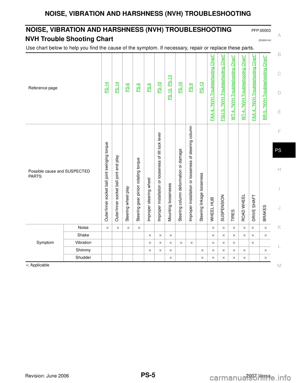
NOISE, VIBRATION AND HARSHNESS (NVH) TROUBLESHOOTINGPFP:00003
NVH Trouble Shooting ChartEGS0014U
Use chart below to help you find the cause of the symptom. If necessary, repair or replace these parts.
×: ApplicableReference page
PS-14PS-14PS-6PS-6PS-6PS-10
PS-12
, PS-13PS-10PS-9PS-13
FA X-4, "
NVH Troubleshooting Chart
"
FSU-5, "
NVH Troubleshooting Chart
"
WT-4, "
NVH Troubleshooting Chart
"
WT-4, "
NVH Troubleshooting Chart
"
FA X-4, "
NVH Troubleshooting Chart
"
BR-5, "
NVH Troubleshooting Chart
"
Possible cause and SUSPECTED
PA R T S
Outer/Inner socket ball joint swinging torque
Outer/Inner socket ball joint end play
Steering wheel play
Steering gear pinion rotating torque
Improper steering wheel
Improper installation or looseness of tilt lock lever
Mounting loosenesss
Steering column deformation or damage
Improper installation or looseness of steering column
Steering linkage looseness
WHEEL HUB
SUSPENSION
TIRES
ROAD WHEEL
DRIVE SHAFT
BRAKES
SymptomNoise××× × ××××× ×
Shake××× ××××× ×
Vibration××××× ××× ×
Shimmy××× × ×××× ×
Shudder× × ×××× ×
Page 2600 of 2896

PS-6
STEERING WHEEL
Revision: June 20062007 Versa
STEERING WHEELPFP:48430
On-Vehicle Inspection and ServiceEGS0014V
CHECKING CONDITION OF INSTALLATION
�Check installation conditions of steering gear assembly, front suspension assembly, axle and steering col-
umn assembly.
�Check if movement exists when steering wheel is moved up and down, to the left and right and to the axial
direction.
�Check steering gear assembly mounting bolts and nuts for looseness. Refer to PS-12, "COMPONENT" .
CHECKING STEERING WHEEL PLAY
�Turn steering wheel so that front wheels come to the straight-ahead position. Start engine and lightly turn
steering wheel to the left and right until front wheels start to move. Measure steering wheel movement on
the outer circumference.
�When the measurement value is outside the standard value, check backlash for each joint of steering col-
umn assembly and installation condition of steering gear assembly.
CHECKING NEUTRAL POSITION STEERING WHEEL
�Make sure that steering gear assembly, steering column assembly and steering wheel are installed in the
correct position.
�Perform neutral position inspection after wheel alignment. Refer to RSU-2, "Precautions for Supplemental
Restraint System (SRS) “AIR BAG” and “SEAT BELT PRE-TENSIONER”" .
�Set vehicle to the straight-ahead position and confirm steering wheel is in the neutral position.
�Loosen outer socket lock nut and turn inner socket to left and right equally to make fine adjustments if
steering wheel is not in the neutral position.
CHECKING STEERING WHEEL TURNING FORCE
1. Park vehicle on a level and dry surface, set parking brake.
2. Start engine.
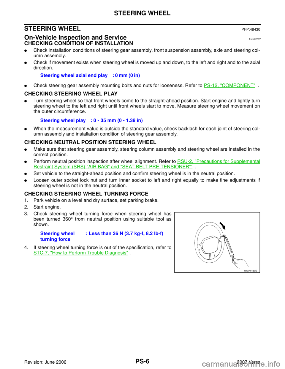
3. Check steering wheel turning force when steering wheel has
been turned 360° from neutral position using suitable tool as
shown.
4. If steering wheel turning force is out of the specification, refer to
STC-7, "
How to Perform Trouble Diagnosis" . Steering wheel axial end play : 0 mm (0 in)
Steering wheel play : 0 - 35 mm (0 - 1.38 in)
Steering wheel
turning force: Less than 36 N (3.7 kg-f, 8.2 lb-f)
WGIA0180E
Page 2615 of 2896
NOISE, VIBRATION AND HARSHNESS (NVH) TROUBLESHOOTING
RAX-3
C
E
F
G
H
I
J
K
L
MA
B
RAX
Revision: June 20062007 Versa
NOISE, VIBRATION AND HARSHNESS (NVH) TROUBLESHOOTINGPFP:00003
NVH Troubleshooting ChartEDS003QZ
Use chart below to help you find the cause of the symptom. If necessary, repair or replace these parts.
×: ApplicableReference page
RAX-4—
RAX-4
NVH in RAX and RSU sections.
NVH in WT section.
NVH in WT section.
NVH in BR section.
NVH in PS section.
Possible cause and SUSPECTED PARTS
Improper installation, looseness
Parts interference
Wheel bearing damage
REAR AXLE AND REAR SUSPENSION
TIRES
ROAD WHEEL
BRAKES
STEERING
Symptom REAR AXLENoise×× ×××××
Shake×× ×××××
Vibration×× ×× ×
Shimmy×× ×××××
Judder× ×××××
Poor quality ride or handling××××××
Page 2617 of 2896

WHEEL HUB
RAX-5
C
E
F
G
H
I
J
K
L
MA
B
RAX
Revision: June 20062007 Versa
CAUTION:
Do not pull on wheel sensor harness.
3. Remove the drum brake assembly. Refer to BR-31, "
Removal and Installation of Drum Brake Assembly" .
4. Remove wheel hub and bearing assembly bolts, and then remove wheel hub and bearing assembly from
vehicle.
5. If necessary remove back plate, following procedure.
1. Remove parking brake rear cable from back plate. Refer to PB-4, "
PARKING BRAKE CONTROL" .
2. Separate brake tube from wheel cylinder. Refer to BR-11, "
BRAKE TUBE AND HOSE" .
INSPECTION AFTER REMOVAL
Check for any deformity, cracks, or other damage on the wheel hub assembly, replace if necessary.
CAUTION:
The wheel hub assembly does not require maintenance. If any of the following symptoms are noted,
replace the wheel hub assembly.
�Growling noise is emitted from the wheel hub bearing during operation.
�Wheel hub bearing drags or turns roughly.
INSTALLATION
Installation is in the reverse order of removal.
Page 2652 of 2896

RSU-4
NOISE, VIBRATION AND HARSHNESS (NVH) TROUBLESHOOTING
Revision: June 20062007 Versa
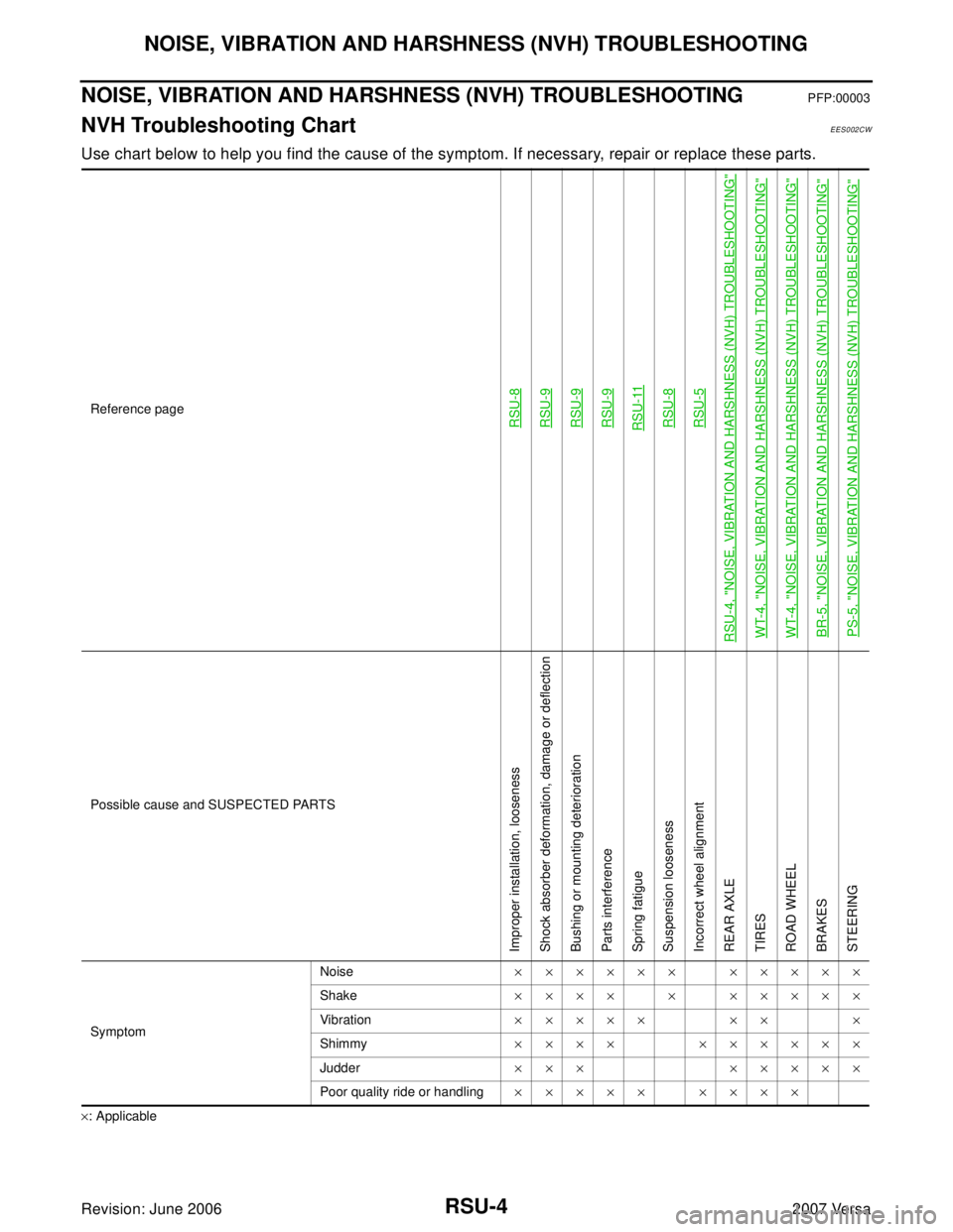
NOISE, VIBRATION AND HARSHNESS (NVH) TROUBLESHOOTINGPFP:00003
NVH Troubleshooting ChartEES002CW
Use chart below to help you find the cause of the symptom. If necessary, repair or replace these parts.
×: ApplicableReference page
RSU-8RSU-9RSU-9RSU-9RSU-11RSU-8RSU-5
RSU-4, "
NOISE, VIBRATION AND HARSHNESS (NVH) TROUBLESHOOTING
"
WT-4, "
NOISE, VIBRATION AND HARSHNESS (NVH) TROUBLESHOOTING
"
WT-4, "
NOISE, VIBRATION AND HARSHNESS (NVH) TROUBLESHOOTING
"
BR-5, "
NOISE, VIBRATION AND HARSHNESS (NVH) TROUBLESHOOTING
"
PS-5, "
NOISE, VIBRATION AND HARSHNESS (NVH) TROUBLESHOOTING
"
Possible cause and SUSPECTED PARTS
Improper installation, looseness
Shock absorber deformation, damage or deflection
Bushing or mounting deterioration
Parts interference
Spring fatigue
Suspension looseness
Incorrect wheel alignment
REAR AXLE
TIRES
ROAD WHEEL
BRAKES
STEERING
SymptomNoise×××××× ×××××
Shake×××× × ×××××
Vib ration××××× ×× ×
Shimmy×××× ××××××
Judder ××× ×××××
Poor quality ride or handling××××× ××××
Page 2656 of 2896
RSU-8
REAR SUSPENSION ASSEMBLY
Revision: June 20062007 Versa
ComponentsEES002CZ
WAIA0110E
1. Washer (upper) 2. Bushing (upper) 3. Bushing (lower)
4. Washer (lower) 5. Distance tube 6. Bound bumper cover
7. Bound bumper 8. Shock absorber 9. Rear spring rubber seat (upper)
10. Coil spring 11. Rear spring rubber seat (lower) 12. Brake tube protector
13. Rear suspension beam 14. Rear suspension beam bracket