Page 1169 of 1226

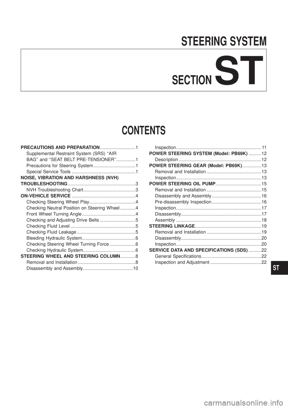
STEERING SYSTEM
SECTION
ST
CONTENTS
PRECAUTIONS AND PREPARATION............................1
Supplemental Restraint System (SRS) ``AIR
BAG'' and ``SEAT BELT PRE-TENSIONER''...............1
Precautions for Steering System .................................1
Special Service Tools ..................................................1
NOISE, VIBRATION AND HARSHNESS (NVH)
TROUBLESHOOTING.....................................................3
NVH Troubleshooting Chart.........................................3
ON-VEHICLE SERVICE..................................................4
Checking Steering Wheel Play ....................................4
Checking Neutral Position on Steering Wheel ............4
Front Wheel Turning Angle ..........................................4
Checking and Adjusting Drive Belts ............................5
Checking Fluid Level ...................................................5
Checking Fluid Leakage ..............................................5
Bleeding Hydraulic System..........................................6
Checking Steering Wheel Turning Force ....................6
Checking Hydraulic System.........................................6
STEERING WHEEL AND STEERING COLUMN............8
Removal and Installation .............................................8
Disassembly and Assembly .......................................10Inspection................................................................... 11
POWER STEERING SYSTEM (Model: PB69K)..........12
Description .................................................................12
POWER STEERING GEAR (Model: PB69K)...............13
Removal and Installation ...........................................13
Inspection...................................................................13
POWER STEERING OIL PUMP....................................15
Removal and Installation ...........................................15
Disassembly and Assembly .......................................16
Pre-disassembly Inspection .......................................16
Inspection...................................................................17
Disassembly...............................................................17
Assembly ...................................................................18
STEERING LINKAGE....................................................19
Removal and Installation ...........................................19
Disassembly...............................................................20
Inspection...................................................................20
SERVICE DATA AND SPECIFICATIONS (SDS)..........22
General Speci®cations ...............................................22
Inspection and Adjustment ........................................22
ST
Page 1191 of 1226
General Speci®cations
Power steering
Steering gear type PB69K
Turns of steering wheel on the vehicle
(Lock-to-lock)3.4
Steering gear ratio 17.0Steering wheel axial play
mm (in)0 (0)
Steering wheel play
mm (in)35 (1.38) or less
Steering damper
[at 0.3 m (1.0 ft)/sec.]
N (kg, lb)4,443 (453, 999) ...
Extended direction
3,315 (338, 745) ...
Compressed direction
Inspection and Adjustment
STEERING COLUMN
Unit: mm (in)
Steering column (L1) 679.9 - 681.5 (26.77 - 26.83)
Steering column lower shaft (L
2) 489.3 - 493.3 (19.26 - 19.42)
STEERING LINKAGE
Tie-rod & drag link ball joint
Swinging force at cotter pin hole N (kg, lb)4.9 - 49.0
(0.5 - 5.0, 1.1 - 11.0)
Rotating torque
Nzm (kg-cm, in-lb)0.3 - 2.9
(3 - 30, 2.6 - 26.0)
Axial end play mm (in) 0 (0)
Tie-rod standard length (L)
mm (in)1,302 (51.26)
Drag link standard length (L)
mm (in)1,123.4 (44.23)
SST761C
SST768C
SST769C
SERVICE DATA AND SPECIFICATIONS (SDS)
ST-22
Page 1192 of 1226
POWER STEERING SYSTEM
(Model: PB69K)
Steering wheel turning force
(at 360É from neutral posi-
tion and circumference of
steering wheel) N (kg, lb)39 (4, 9) or less
Oil pump pressure
kPa (bar, kg/cm
2, psi)8,140 - 8,728
(81.4 - 87.3, 83 - 89, 1,180 - 1,266)
at idling
Fluid capacity
m!(Imp ¯ oz)Approximately 1,000 (35.2)
Normal operating tempera-
ture ÉC (ÉF)60 - 80 (140 - 176)
Steering gear turning torque
Nzm (kg-cm, in-lb)
360É position from
straight-ahead position0.15 - 0.78 (1.5 - 8.0, 1.3 - 6.9)
Straight-ahead position
(As compared with steer-
ing wheel turned 360É)0.2 - 0.5 (2 - 5, 1.7 - 4.3) higher
Maximum turning torque 0.44 - 1.18 (4.5 - 12, 3.9 - 10.4)
Backlash at pitman arm top
end (in a straight-
ahead position) mm (in)0 - 0.1 (0 - 0.004)
End play (at sector shaft
end in neutral position)
mm (in)0.1 (0.004) or less
SERVICE DATA AND SPECIFICATIONS (SDS)
Inspection and Adjustment (Cont'd)
ST-23
Page 1193 of 1226

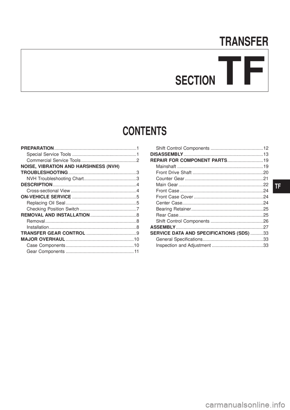
TRANSFER
SECTION
TF
CONTENTS
PREPARATION................................................................1
Special Service Tools ..................................................1
Commercial Service Tools ...........................................2
NOISE, VIBRATION AND HARSHNESS (NVH)
TROUBLESHOOTING.....................................................3
NVH Troubleshooting Chart.........................................3
DESCRIPTION.................................................................4
Cross-sectional View ...................................................4
ON-VEHICLE SERVICE..................................................5
Replacing Oil Seal .......................................................5
Checking Position Switch ............................................7
REMOVAL AND INSTALLATION....................................8
Removal .......................................................................8
Installation ....................................................................8
TRANSFER GEAR CONTROL.......................................9
MAJOR OVERHAUL.....................................................10
Case Components .....................................................10
Gear Components ..................................................... 11Shift Control Components .........................................12
DISASSEMBLY..............................................................13
REPAIR FOR COMPONENT PARTS............................19
Mainshaft ...................................................................19
Front Drive Shaft .......................................................20
Counter Gear .............................................................21
Main Gear ..................................................................22
Front Case .................................................................24
Front Case Cover ......................................................24
Center Case...............................................................24
Bearing Retainer ........................................................25
Rear Case..................................................................25
Shift Control Components .........................................26
ASSEMBLY....................................................................27
SERVICE DATA AND SPECIFICATIONS (SDS)..........33
General Speci®cations ...............................................33
Inspection and Adjustment ........................................33
TF
Page 1226 of 1226

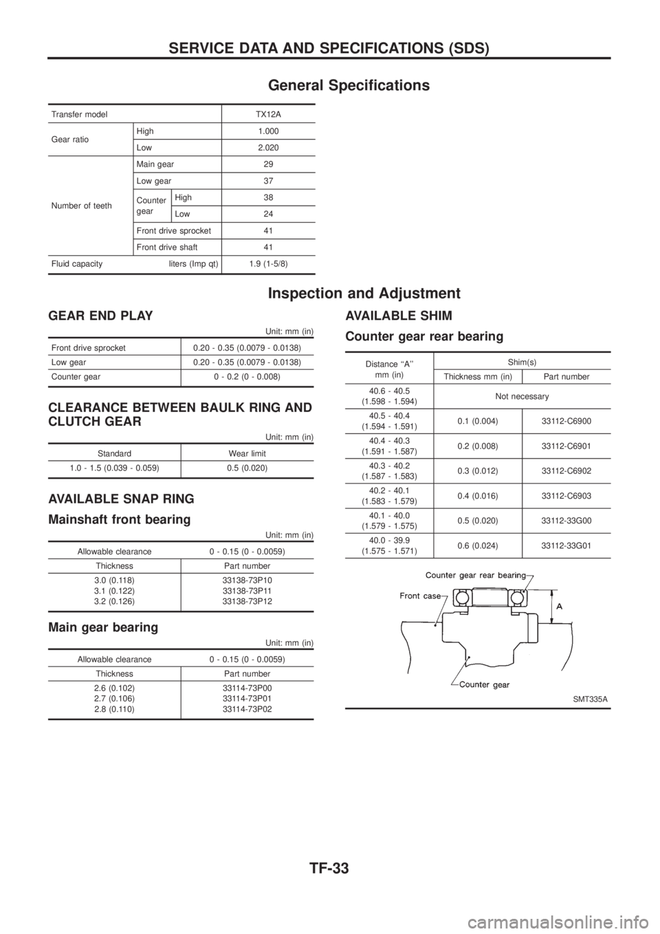
General Speci®cations
Transfer model TX12A
Gear ratioHigh 1.000
Low 2.020
Number of teethMain gear 29
Low gear 37
Counter
gearHigh 38
Low 24
Front drive sprocket 41
Front drive shaft 41
Fluid capacity liters (Imp qt) 1.9 (1-5/8)
Inspection and Adjustment
GEAR END PLAY
Unit: mm (in)
Front drive sprocket 0.20 - 0.35 (0.0079 - 0.0138)
Low gear 0.20 - 0.35 (0.0079 - 0.0138)
Counter gear 0 - 0.2 (0 - 0.008)
CLEARANCE BETWEEN BAULK RING AND
CLUTCH GEAR
Unit: mm (in)
Standard Wear limit
1.0 - 1.5 (0.039 - 0.059) 0.5 (0.020)
AVAILABLE SNAP RING
Mainshaft front bearing
Unit: mm (in)
Allowable clearance 0 - 0.15 (0 - 0.0059)
Thickness Part number
3.0 (0.118)
3.1 (0.122)
3.2 (0.126)33138-73P10
33138-73P11
33138-73P12
Main gear bearing
Unit: mm (in)
Allowable clearance 0 - 0.15 (0 - 0.0059)
Thickness Part number
2.6 (0.102)
2.7 (0.106)
2.8 (0.110)33114-73P00
33114-73P01
33114-73P02
AVAILABLE SHIM
Counter gear rear bearing
Distance ``A''
mm (in)Shim(s)
Thickness mm (in) Part number
40.6 - 40.5
(1.598 - 1.594)Not necessary
40.5 - 40.4
(1.594 - 1.591)0.1 (0.004) 33112-C6900
40.4 - 40.3
(1.591 - 1.587)0.2 (0.008) 33112-C6901
40.3 - 40.2
(1.587 - 1.583)0.3 (0.012) 33112-C6902
40.2 - 40.1
(1.583 - 1.579)0.4 (0.016) 33112-C6903
40.1 - 40.0
(1.579 - 1.575)0.5 (0.020) 33112-33G00
40.0 - 39.9
(1.575 - 1.571)0.6 (0.024) 33112-33G01
SMT335A
SERVICE DATA AND SPECIFICATIONS (SDS)
TF-33