2006 NISSAN PATROL Specifications
[x] Cancel search: SpecificationsPage 730 of 1226
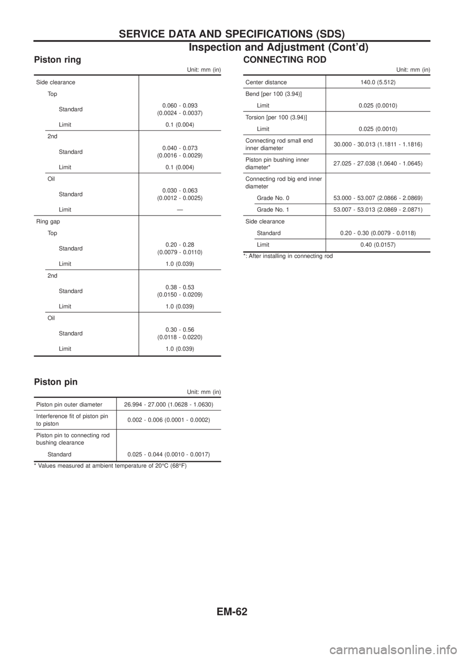
Piston ring
Unit: mm (in)
Side clearance
To p
Standard0.060 - 0.093
(0.0024 - 0.0037)
Limit 0.1 (0.004)
2nd
Standard0.040 - 0.073
(0.0016 - 0.0029)
Limit 0.1 (0.004)
Oil
Standard0.030 - 0.063
(0.0012 - 0.0025)
Limit Ð
Ring gap
To p
Standard0.20 - 0.28
(0.0079 - 0.0110)
Limit 1.0 (0.039)
2nd
Standard0.38 - 0.53
(0.0150 - 0.0209)
Limit 1.0 (0.039)
Oil
Standard0.30 - 0.56
(0.0118 - 0.0220)
Limit 1.0 (0.039)
Piston pin
Unit: mm (in)
Piston pin outer diameter 26.994 - 27.000 (1.0628 - 1.0630)
Interference ®t of piston pin
to piston0.002 - 0.006 (0.0001 - 0.0002)
Piston pin to connecting rod
bushing clearance
Standard 0.025 - 0.044 (0.0010 - 0.0017)
* Values measured at ambient temperature of 20ÉC (68ÉF)
CONNECTING ROD
Unit: mm (in)
Center distance 140.0 (5.512)
Bend [per 100 (3.94)]
Limit 0.025 (0.0010)
Torsion [per 100 (3.94)]
Limit 0.025 (0.0010)
Connecting rod small end
inner diameter30.000 - 30.013 (1.1811 - 1.1816)
Piston pin bushing inner
diameter*27.025 - 27.038 (1.0640 - 1.0645)
Connecting rod big end inner
diameter
Grade No. 0 53.000 - 53.007 (2.0866 - 2.0869)
Grade No. 1 53.007 - 53.013 (2.0869 - 2.0871)
Side clearance
Standard 0.20 - 0.30 (0.0079 - 0.0118)
Limit 0.40 (0.0157)
*: After installing in connecting rod
SERVICE DATA AND SPECIFICATIONS (SDS)
Inspection and Adjustment (Cont'd)
EM-62
Page 731 of 1226
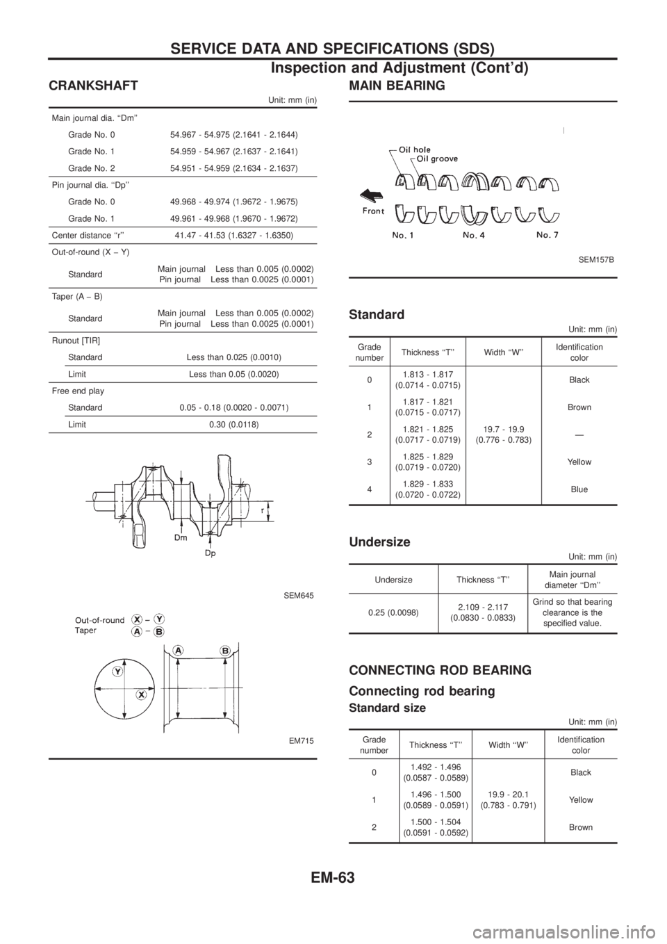
CRANKSHAFT
Unit: mm (in)
Main journal dia. ``Dm''
Grade No. 0 54.967 - 54.975 (2.1641 - 2.1644)
Grade No. 1 54.959 - 54.967 (2.1637 - 2.1641)
Grade No. 2 54.951 - 54.959 (2.1634 - 2.1637)
Pin journal dia. ``Dp''
Grade No. 0 49.968 - 49.974 (1.9672 - 1.9675)
Grade No. 1 49.961 - 49.968 (1.9670 - 1.9672)
Center distance ``r'' 41.47 - 41.53 (1.6327 - 1.6350)
Out-of-round (X þ Y)
Standard
Main journal Less than 0.005 (0.0002)
Pin journal Less than 0.0025 (0.0001)
Taper (A þ B)
Standard
Main journal Less than 0.005 (0.0002)
Pin journal Less than 0.0025 (0.0001)
Runout [TIR]
Standard Less than 0.025 (0.0010)
Limit Less than 0.05 (0.0020)
Free end play
Standard 0.05 - 0.18 (0.0020 - 0.0071)
Limit 0.30 (0.0118)
SEM645
EM715
MAIN BEARING
SEM157B
Standard
Unit: mm (in)
Grade
numberThickness ``T'' Width ``W''Identi®cation
color
01.813 - 1.817
(0.0714 - 0.0715)
19.7 - 19.9
(0.776 - 0.783)Black
11.817 - 1.821
(0.0715 - 0.0717)Brown
21.821 - 1.825
(0.0717 - 0.0719)Ð
31.825 - 1.829
(0.0719 - 0.0720)Yellow
41.829 - 1.833
(0.0720 - 0.0722)Blue
Undersize
Unit: mm (in)
Undersize Thickness ``T''Main journal
diameter ``Dm''
0.25 (0.0098)2.109 - 2.117
(0.0830 - 0.0833)Grind so that bearing
clearance is the
speci®ed value.
CONNECTING ROD BEARING
Connecting rod bearing
Standard size
Unit: mm (in)
Grade
numberThickness ``T'' Width ``W''Identi®cation
color
01.492 - 1.496
(0.0587 - 0.0589)
19.9 - 20.1
(0.783 - 0.791)Black
11.496 - 1.500
(0.0589 - 0.0591)Yellow
21.500 - 1.504
(0.0591 - 0.0592)Brown
SERVICE DATA AND SPECIFICATIONS (SDS)
Inspection and Adjustment (Cont'd)
EM-63
Page 732 of 1226
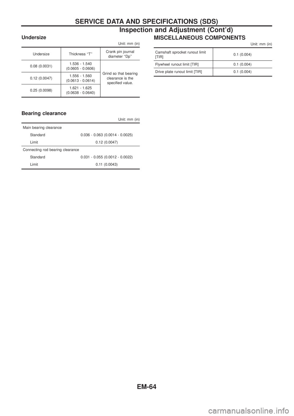
Undersize
Unit: mm (in)
Undersize Thickness ``T''Crank pin journal
diameter ``Dp''
0.08 (0.0031)1.536 - 1.540
(0.0605 - 0.0606)
Grind so that bearing
clearance is the
speci®ed value. 0.12 (0.0047)1.556 - 1.560
(0.0613 - 0.0614)
0.25 (0.0098)1.621 - 1.625
(0.0638 - 0.0640)
Bearing clearance
Unit: mm (in)
Main bearing clearance
Standard 0.036 - 0.063 (0.0014 - 0.0025)
Limit 0.12 (0.0047)
Connecting rod bearing clearance
Standard 0.031 - 0.055 (0.0012 - 0.0022)
Limit 0.11 (0.0043)
MISCELLANEOUS COMPONENTS
Unit: mm (in)
Camshaft sprocket runout limit
[TIR]0.1 (0.004)
Flywheel runout limit [TIR] 0.1 (0.004)
Drive plate runout limit [TIR] 0.1 (0.004)
SERVICE DATA AND SPECIFICATIONS (SDS)
Inspection and Adjustment (Cont'd)
EM-64
Page 733 of 1226
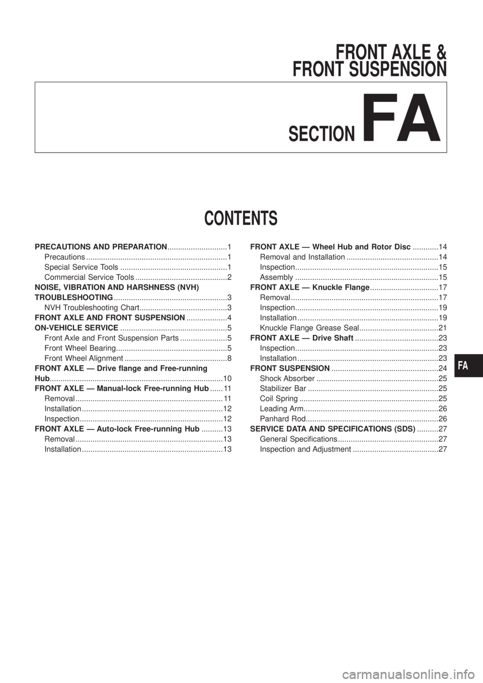
FRONT AXLE &
FRONT SUSPENSION
SECTION
FA
CONTENTS
PRECAUTIONS AND PREPARATION............................1
Precautions ..................................................................1
Special Service Tools ..................................................1
Commercial Service Tools ...........................................2
NOISE, VIBRATION AND HARSHNESS (NVH)
TROUBLESHOOTING.....................................................3
NVH Troubleshooting Chart.........................................3
FRONT AXLE AND FRONT SUSPENSION...................4
ON-VEHICLE SERVICE..................................................5
Front Axle and Front Suspension Parts ......................5
Front Wheel Bearing....................................................5
Front Wheel Alignment ................................................8
FRONT AXLE Ð Drive ¯ange and Free-running
Hub.................................................................................10
FRONT AXLE Ð Manual-lock Free-running Hub...... 11
Removal ..................................................................... 11
Installation ..................................................................12
Inspection...................................................................12
FRONT AXLE Ð Auto-lock Free-running Hub..........13
Removal .....................................................................13
Installation ..................................................................13FRONT AXLE Ð Wheel Hub and Rotor Disc............14
Removal and Installation ...........................................14
Inspection...................................................................15
Assembly ...................................................................15
FRONT AXLE Ð Knuckle Flange................................17
Removal .....................................................................17
Inspection...................................................................19
Installation ..................................................................19
Knuckle Flange Grease Seal.....................................21
FRONT AXLE Ð Drive Shaft.......................................23
Inspection...................................................................23
Installation ..................................................................23
FRONT SUSPENSION..................................................24
Shock Absorber .........................................................25
Stabilizer Bar .............................................................25
Coil Spring .................................................................25
Leading Arm...............................................................26
Panhard Rod..............................................................26
SERVICE DATA AND SPECIFICATIONS (SDS)..........27
General Speci®cations ...............................................27
Inspection and Adjustment ........................................27
FA
Page 760 of 1226
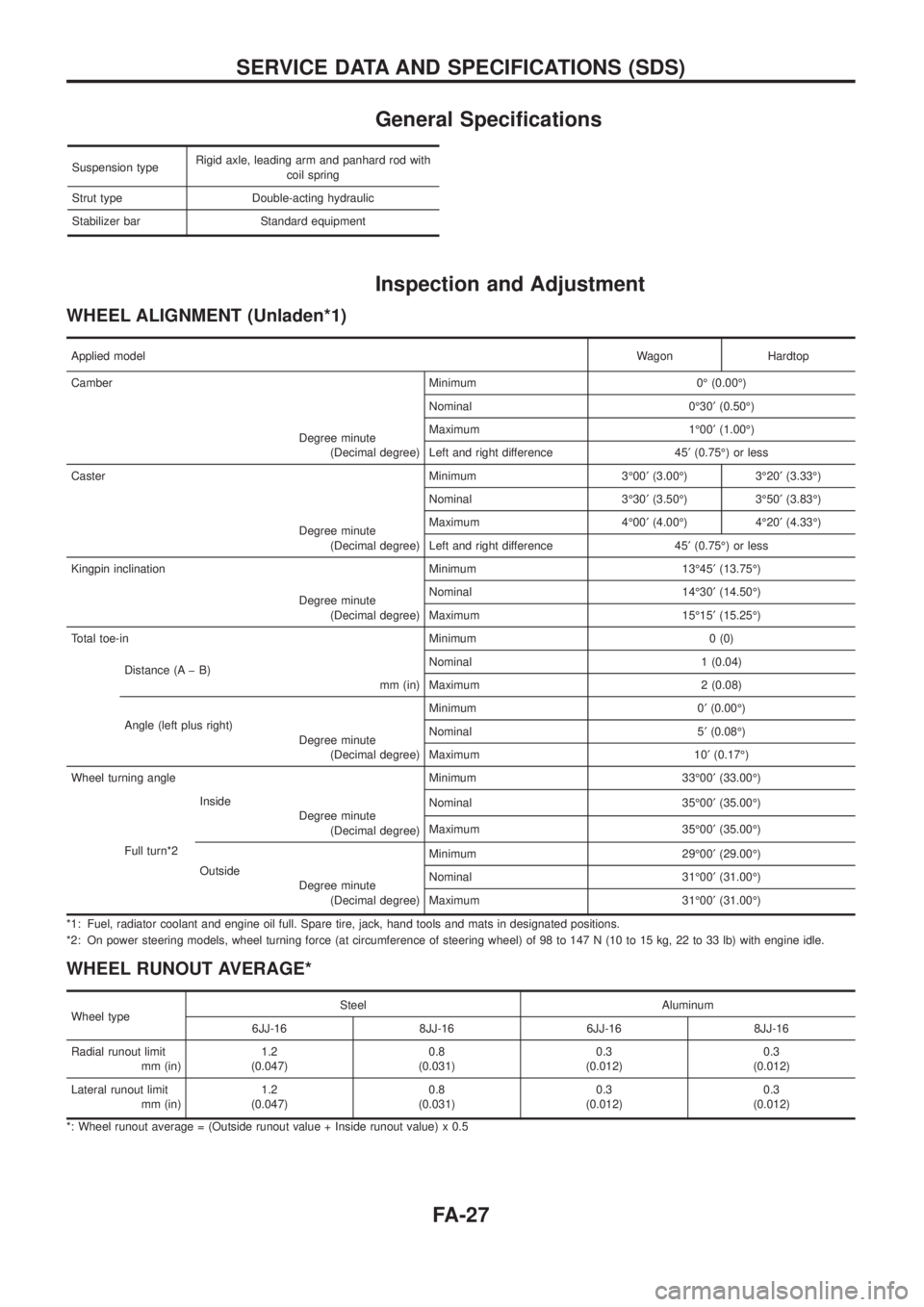
General Speci®cations
Suspension typeRigid axle, leading arm and panhard rod with
coil spring
Strut type Double-acting hydraulic
Stabilizer bar Standard equipment
Inspection and Adjustment
WHEEL ALIGNMENT (Unladen*1)
Applied modelWagon Hardtop
Camber Minimum 0É (0.00É)
Degree minute
(Decimal degree)Nominal 0É30¢(0.50É)
Maximum 1É00¢(1.00É)
Left and right difference 45¢(0.75É) or less
Caster Minimum 3É00¢(3.00É) 3É20¢(3.33É)
Degree minute
(Decimal degree)Nominal 3É30¢(3.50É) 3É50¢(3.83É)
Maximum 4É00¢(4.00É) 4É20¢(4.33É)
Left and right difference 45¢(0.75É) or less
Kingpin inclination Minimum 13É45¢(13.75É)
Degree minute
(Decimal degree)Nominal 14É30¢(14.50É)
Maximum 15É15¢(15.25É)
Total toe-in Minimum 0 (0)
Distance (A þ B)
mm (in)Nominal 1 (0.04)
Maximum 2 (0.08)
Angle (left plus right)
Degree minute
(Decimal degree)Minimum 0¢(0.00É)
Nominal 5¢(0.08É)
Maximum 10¢(0.17É)
Wheel turning angle Minimum 33É00¢(33.00É)
Full turn*2Inside
Degree minute
(Decimal degree)Nominal 35É00¢(35.00É)
Maximum 35É00¢(35.00É)
Outside
Degree minute
(Decimal degree)Minimum 29É00¢(29.00É)
Nominal 31É00¢(31.00É)
Maximum 31É00¢(31.00É)
*1: Fuel, radiator coolant and engine oil full. Spare tire, jack, hand tools and mats in designated positions.
*2: On power steering models, wheel turning force (at circumference of steering wheel) of 98 to 147 N (10 to 15 kg, 22 to 33 lb) with engine idle.
WHEEL RUNOUT AVERAGE*
Wheel typeSteel Aluminum
6JJ-16 8JJ-16 6JJ-16 8JJ-16
Radial runout limit
mm (in)1.2
(0.047)0.8
(0.031)0.3
(0.012)0.3
(0.012)
Lateral runout limit
mm (in)1.2
(0.047)0.8
(0.031)0.3
(0.012)0.3
(0.012)
*: Wheel runout average = (Outside runout value + Inside runout value) x 0.5
SERVICE DATA AND SPECIFICATIONS (SDS)
FA-27
Page 761 of 1226
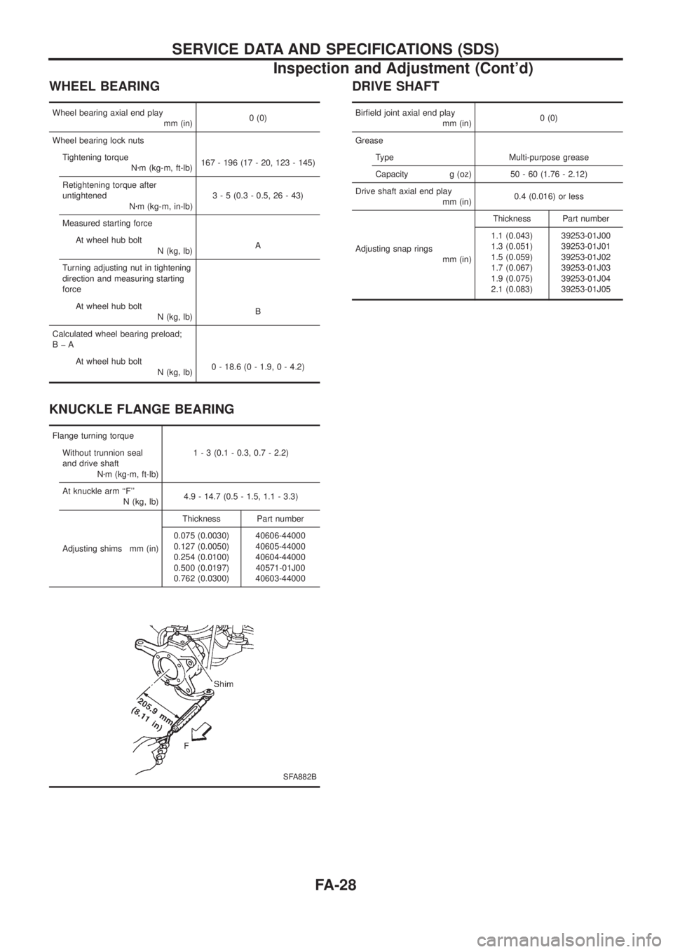
WHEEL BEARING
Wheel bearing axial end play
mm (in)0 (0)
Wheel bearing lock nuts
Tightening torque
Nzm (kg-m, ft-lb)167 - 196 (17 - 20, 123 - 145)
Retightening torque after
untightened
Nzm (kg-m, in-lb)3 - 5 (0.3 - 0.5, 26 - 43)
Measured starting force
At wheel hub bolt
N (kg, lb)A
Turning adjusting nut in tightening
direction and measuring starting
force
At wheel hub bolt
N (kg, lb)B
Calculated wheel bearing preload;
BþA
At wheel hub bolt
N (kg, lb)0 - 18.6 (0 - 1.9, 0 - 4.2)
KNUCKLE FLANGE BEARING
Flange turning torque
Without trunnion seal
and drive shaft
Nzm (kg-m, ft-lb)1 - 3 (0.1 - 0.3, 0.7 - 2.2)
At knuckle arm ``F''
N (kg, lb)4.9 - 14.7 (0.5 - 1.5, 1.1 - 3.3)
Adjusting shims mm (in)Thickness Part number
0.075 (0.0030)
0.127 (0.0050)
0.254 (0.0100)
0.500 (0.0197)
0.762 (0.0300)40606-44000
40605-44000
40604-44000
40571-01J00
40603-44000
SFA882B
DRIVE SHAFT
Bir®eld joint axial end play
mm (in)0 (0)
Grease
Type Multi-purpose grease
Capacity g (oz) 50 - 60 (1.76 - 2.12)
Drive shaft axial end play
mm (in)0.4 (0.016) or less
Adjusting snap rings
mm (in)Thickness Part number
1.1 (0.043)
1.3 (0.051)
1.5 (0.059)
1.7 (0.067)
1.9 (0.075)
2.1 (0.083)39253-01J00
39253-01J01
39253-01J02
39253-01J03
39253-01J04
39253-01J05
SERVICE DATA AND SPECIFICATIONS (SDS)
Inspection and Adjustment (Cont'd)
FA-28
Page 780 of 1226
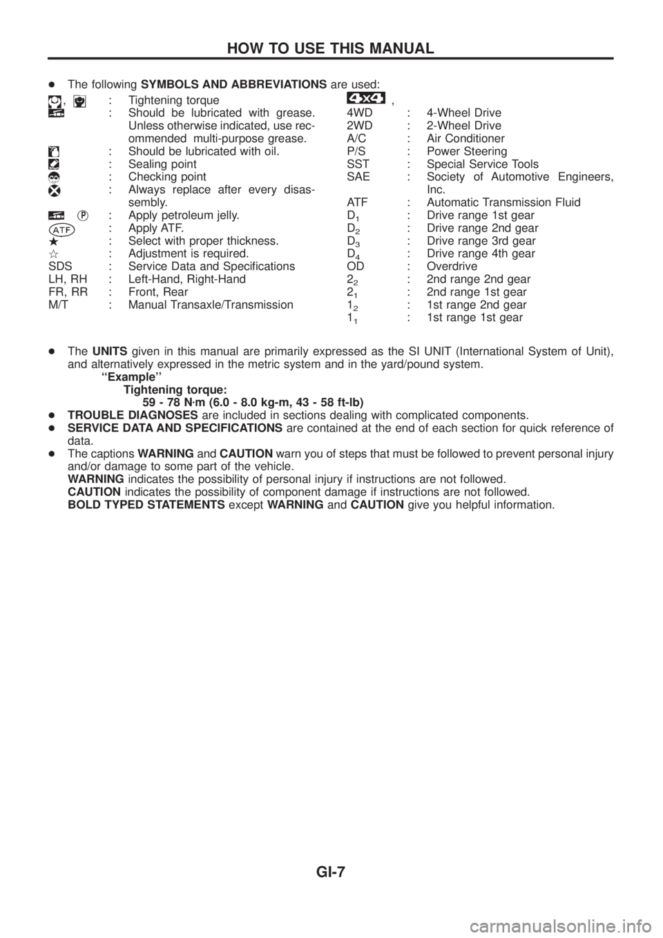
+The followingSYMBOLS AND ABBREVIATIONSare used:
,: Tightening torque
: Should be lubricated with grease.
Unless otherwise indicated, use rec-
ommended multi-purpose grease.
: Should be lubricated with oil.
: Sealing point
: Checking point
: Always replace after every disas-
sembly.
jP: Apply petroleum jelly.
: Apply ATF.
.: Select with proper thickness.
>: Adjustment is required.
SDS : Service Data and Speci®cations
LH, RH : Left-Hand, Right-Hand
FR, RR : Front, Rear
M/T : Manual Transaxle/Transmission
,
4WD : 4-Wheel Drive
2WD : 2-Wheel Drive
A/C : Air Conditioner
P/S : Power Steering
SST : Special Service Tools
SAE : Society of Automotive Engineers,
Inc.
ATF : Automatic Transmission Fluid
D
1: Drive range 1st gear
D
2: Drive range 2nd gear
D
3: Drive range 3rd gear
D
4: Drive range 4th gear
OD : Overdrive
2
2: 2nd range 2nd gear
2
1: 2nd range 1st gear
1
2: 1st range 2nd gear
1
1: 1st range 1st gear
+TheUNITSgiven in this manual are primarily expressed as the SI UNIT (International System of Unit),
and alternatively expressed in the metric system and in the yard/pound system.
``Example''
Tightening torque:
59-78Nzm (6.0 - 8.0 kg-m, 43 - 58 ft-lb)
+TROUBLE DIAGNOSESare included in sections dealing with complicated components.
+SERVICE DATA AND SPECIFICATIONSare contained at the end of each section for quick reference of
data.
+The captionsWARNINGandCAUTIONwarn you of steps that must be followed to prevent personal injury
and/or damage to some part of the vehicle.
WARNINGindicates the possibility of personal injury if instructions are not followed.
CAUTIONindicates the possibility of component damage if instructions are not followed.
BOLD TYPED STATEMENTSexceptWARNINGandCAUTIONgive you helpful information.
HOW TO USE THIS MANUAL
GI-7
Page 821 of 1226
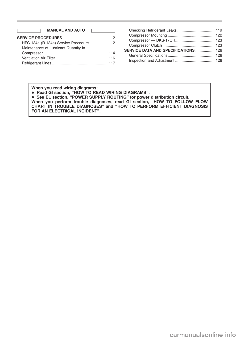
MANUAL AND AUTO
SERVICE PROCEDURES........................................... 112
HFC-134a (R-134a) Service Procedure .................. 112
Maintenance of Lubricant Quantity in
Compressor ............................................................. 114
Ventilation Air Filter .................................................. 116
Refrigerant Lines ..................................................... 117Checking Refrigerant Leaks .................................... 119
Compressor Mounting .............................................122
Compressor Ð DKS-17CH......................................123
Compressor Clutch ..................................................123
SERVICE DATA AND SPECIFICATIONS...................126
General Speci®cations .............................................126
Inspection and Adjustment ......................................126
When you read wiring diagrams:
+Read GI section, ``HOW TO READ WIRING DIAGRAMS''.
+See EL section, ``POWER SUPPLY ROUTING'' for power distribution circuit.
When you perform trouble diagnoses, read GI section, ``HOW TO FOLLOW FLOW
CHART IN TROUBLE DIAGNOSES'' and ``HOW TO PERFORM EFFICIENT DIAGNOSIS
FOR AN ELECTRICAL INCIDENT''.