2006 NISSAN PATROL Specifications
[x] Cancel search: SpecificationsPage 832 of 1226
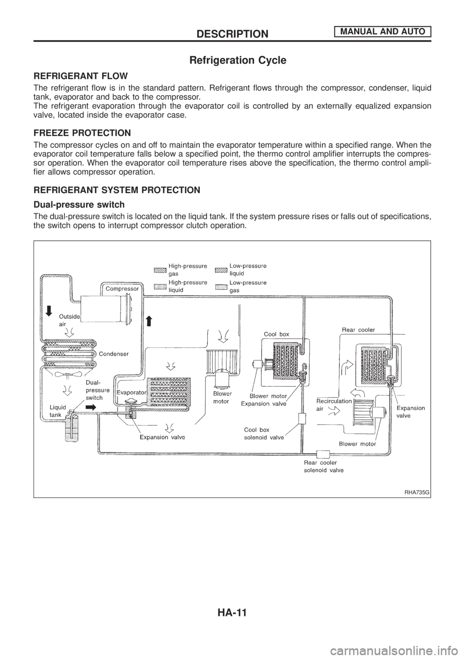
Refrigeration Cycle
REFRIGERANT FLOW
The refrigerant ¯ow is in the standard pattern. Refrigerant ¯ows through the compressor, condenser, liquid
tank, evaporator and back to the compressor.
The refrigerant evaporation through the evaporator coil is controlled by an externally equalized expansion
valve, located inside the evaporator case.
FREEZE PROTECTION
The compressor cycles on and off to maintain the evaporator temperature within a speci®ed range. When the
evaporator coil temperature falls below a speci®ed point, the thermo control ampli®er interrupts the compres-
sor operation. When the evaporator coil temperature rises above the speci®cation, the thermo control ampli-
®er allows compressor operation.
REFRIGERANT SYSTEM PROTECTION
Dual-pressure switch
The dual-pressure switch is located on the liquid tank. If the system pressure rises or falls out of specifications,
the switch opens to interrupt compressor clutch operation.
RHA735G
DESCRIPTIONMANUAL AND AUTO
HA-11
Page 947 of 1226
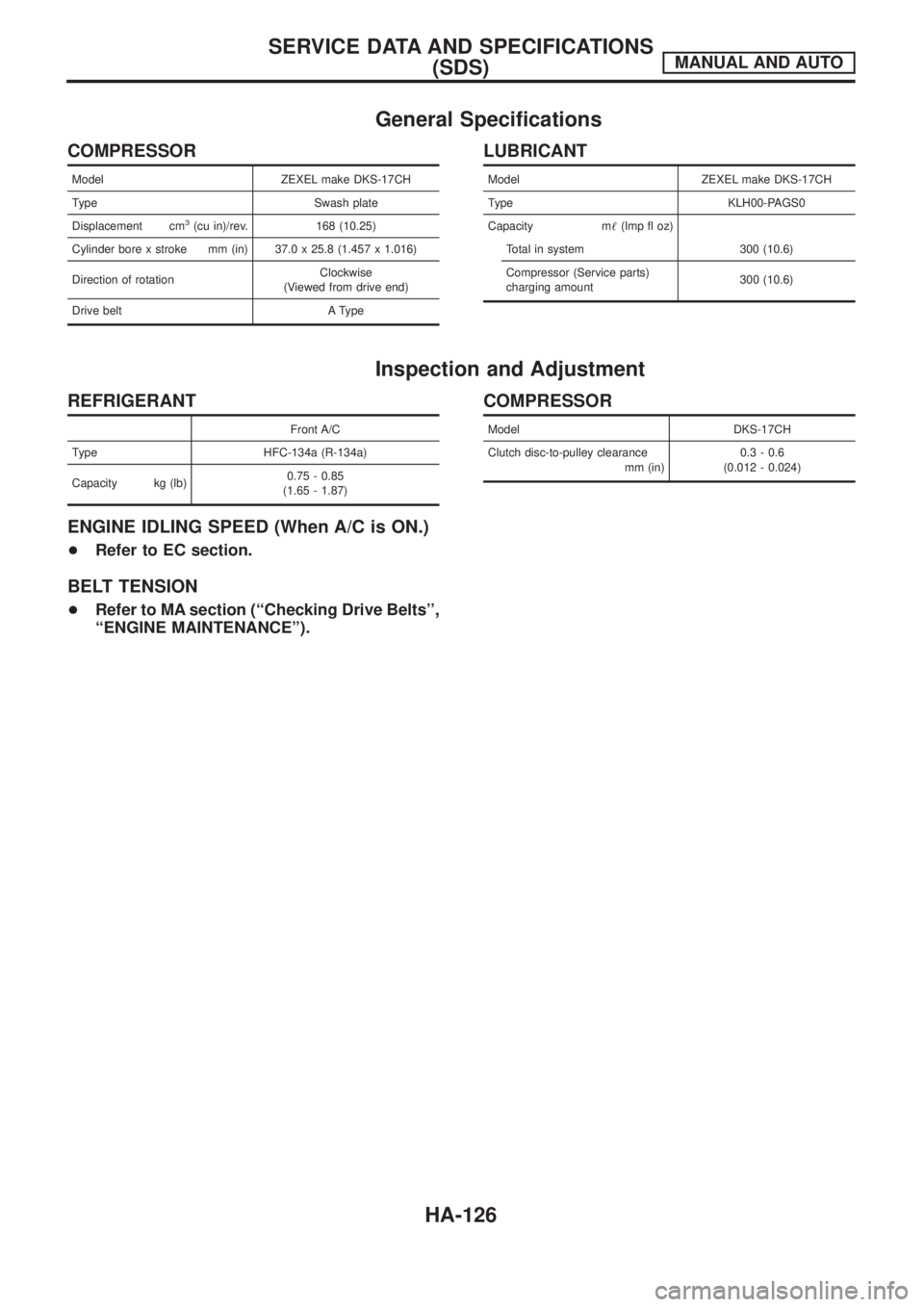
General Speci®cations
COMPRESSOR
Model ZEXEL make DKS-17CH
Type Swash plate
Displacement cm
3(cu in)/rev. 168 (10.25)
Cylinder bore x stroke mm (in) 37.0 x 25.8 (1.457 x 1.016)
Direction of rotationClockwise
(Viewed from drive end)
Drive belt A Type
LUBRICANT
Model ZEXEL make DKS-17CH
Type KLH00-PAGS0
Capacity m!(lmp ¯ oz)
Total in system 300 (10.6)
Compressor (Service parts)
charging amount300 (10.6)
Inspection and Adjustment
REFRIGERANT
Front A/C
Type HFC-134a (R-134a)
Capacity kg (lb)0.75 - 0.85
(1.65 - 1.87)
ENGINE IDLING SPEED (When A/C is ON.)
+Refer to EC section.
BELT TENSION
+Refer to MA section (``Checking Drive Belts'',
``ENGINE MAINTENANCE'').
COMPRESSOR
Model DKS-17CH
Clutch disc-to-pulley clearance
mm (in)0.3 - 0.6
(0.012 - 0.024)
SERVICE DATA AND SPECIFICATIONS
(SDS)MANUAL AND AUTO
HA-126
Page 955 of 1226
ENGINE LUBRICATION &
COOLING SYSTEMS
SECTION
LC
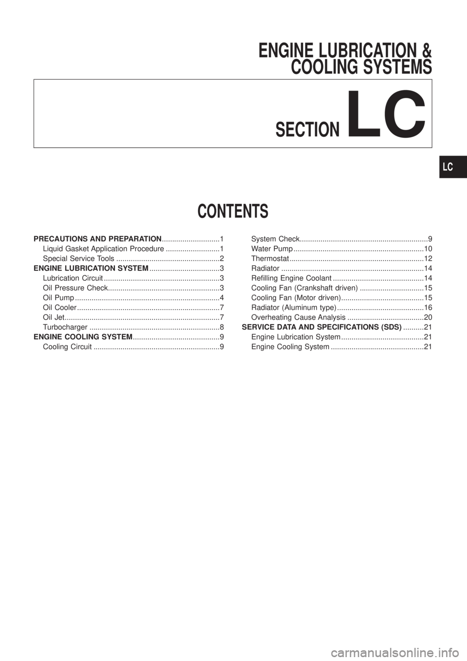
CONTENTS
PRECAUTIONS AND PREPARATION............................1
Liquid Gasket Application Procedure ..........................1
Special Service Tools ..................................................2
ENGINE LUBRICATION SYSTEM..................................3
Lubrication Circuit ........................................................3
Oil Pressure Check......................................................3
Oil Pump ......................................................................4
Oil Cooler .....................................................................7
Oil Jet...........................................................................7
Turbocharger ...............................................................8
ENGINE COOLING SYSTEM..........................................9
Cooling Circuit .............................................................9System Check..............................................................9
Water Pump ...............................................................10
Thermostat .................................................................12
Radiator .....................................................................14
Re®lling Engine Coolant ............................................14
Cooling Fan (Crankshaft driven) ...............................15
Cooling Fan (Motor driven)........................................15
Radiator (Aluminum type) ..........................................16
Overheating Cause Analysis .....................................20
SERVICE DATA AND SPECIFICATIONS (SDS)..........21
Engine Lubrication System ........................................21
Engine Cooling System .............................................21
LC
Page 976 of 1226
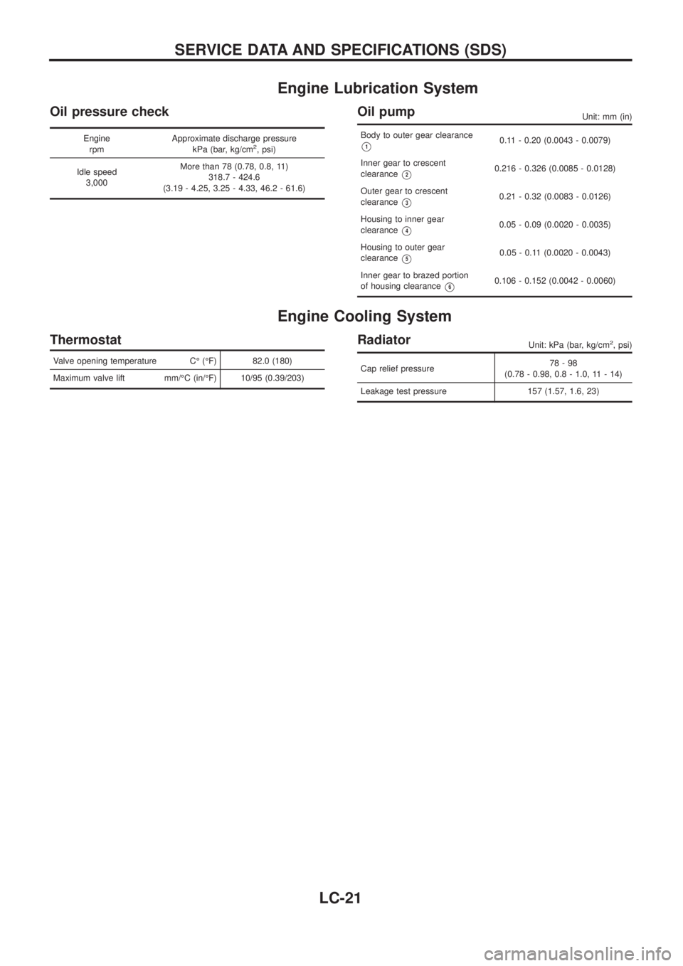
Engine Lubrication System
Oil pressure check
Engine
rpmApproximate discharge pressure
kPa (bar, kg/cm2, psi)
Idle speed
3,000More than 78 (0.78, 0.8, 11)
318.7 - 424.6
(3.19 - 4.25, 3.25 - 4.33, 46.2 - 61.6)
Oil pumpUnit: mm (in)
Body to outer gear clearance
V10.11 - 0.20 (0.0043 - 0.0079)
Inner gear to crescent
clearance
V20.216 - 0.326 (0.0085 - 0.0128)
Outer gear to crescent
clearance
V30.21 - 0.32 (0.0083 - 0.0126)
Housing to inner gear
clearance
V40.05 - 0.09 (0.0020 - 0.0035)
Housing to outer gear
clearance
V50.05 - 0.11 (0.0020 - 0.0043)
Inner gear to brazed portion
of housing clearance
V60.106 - 0.152 (0.0042 - 0.0060)
Engine Cooling System
Thermostat
Valve opening temperature CÉ (ÉF) 82.0 (180)
Maximum valve lift mm/ÉC (in/ÉF) 10/95 (0.39/203)
RadiatorUnit: kPa (bar, kg/cm2, psi)
Cap relief pressure78-98
(0.78 - 0.98, 0.8 - 1.0, 11 - 14)
Leakage test pressure 157 (1.57, 1.6, 23)
SERVICE DATA AND SPECIFICATIONS (SDS)
LC-21
Page 977 of 1226
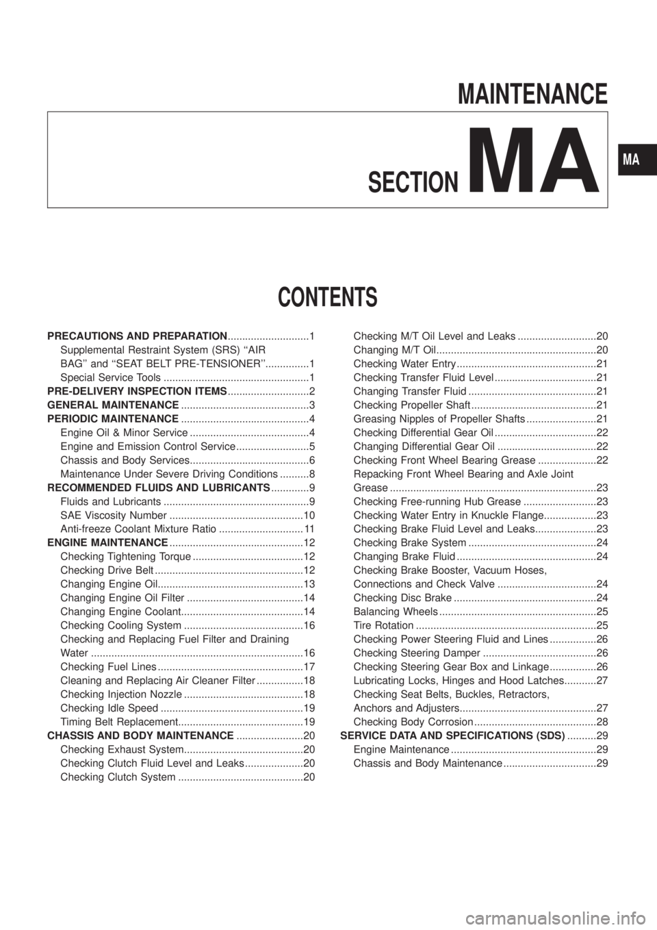
MAINTENANCE
SECTION
MA
CONTENTS
PRECAUTIONS AND PREPARATION............................1
Supplemental Restraint System (SRS) ``AIR
BAG'' and ``SEAT BELT PRE-TENSIONER''...............1
Special Service Tools ..................................................1
PRE-DELIVERY INSPECTION ITEMS............................2
GENERAL MAINTENANCE............................................3
PERIODIC MAINTENANCE............................................4
Engine Oil & Minor Service .........................................4
Engine and Emission Control Service .........................5
Chassis and Body Services.........................................6
Maintenance Under Severe Driving Conditions ..........8
RECOMMENDED FLUIDS AND LUBRICANTS.............9
Fluids and Lubricants ..................................................9
SAE Viscosity Number ..............................................10
Anti-freeze Coolant Mixture Ratio ............................. 11
ENGINE MAINTENANCE..............................................12
Checking Tightening Torque ......................................12
Checking Drive Belt ...................................................12
Changing Engine Oil..................................................13
Changing Engine Oil Filter ........................................14
Changing Engine Coolant..........................................14
Checking Cooling System .........................................16
Checking and Replacing Fuel Filter and Draining
Water .........................................................................16
Checking Fuel Lines ..................................................17
Cleaning and Replacing Air Cleaner Filter ................18
Checking Injection Nozzle .........................................18
Checking Idle Speed .................................................19
Timing Belt Replacement...........................................19
CHASSIS AND BODY MAINTENANCE.......................20
Checking Exhaust System.........................................20
Checking Clutch Fluid Level and Leaks ....................20
Checking Clutch System ...........................................20Checking M/T Oil Level and Leaks ...........................20
Changing M/T Oil.......................................................20
Checking Water Entry ................................................21
Checking Transfer Fluid Level ...................................21
Changing Transfer Fluid ............................................21
Checking Propeller Shaft ...........................................21
Greasing Nipples of Propeller Shafts ........................21
Checking Differential Gear Oil ...................................22
Changing Differential Gear Oil ..................................22
Checking Front Wheel Bearing Grease ....................22
Repacking Front Wheel Bearing and Axle Joint
Grease .......................................................................23
Checking Free-running Hub Grease .........................23
Checking Water Entry in Knuckle Flange..................23
Checking Brake Fluid Level and Leaks.....................23
Checking Brake System ............................................24
Changing Brake Fluid ................................................24
Checking Brake Booster, Vacuum Hoses,
Connections and Check Valve ..................................24
Checking Disc Brake .................................................24
Balancing Wheels ......................................................25
Tire Rotation ..............................................................25
Checking Power Steering Fluid and Lines ................26
Checking Steering Damper .......................................26
Checking Steering Gear Box and Linkage ................26
Lubricating Locks, Hinges and Hood Latches...........27
Checking Seat Belts, Buckles, Retractors,
Anchors and Adjusters...............................................27
Checking Body Corrosion ..........................................28
SERVICE DATA AND SPECIFICATIONS (SDS)..........29
Engine Maintenance ..................................................29
Chassis and Body Maintenance ................................29
MA
Page 1006 of 1226
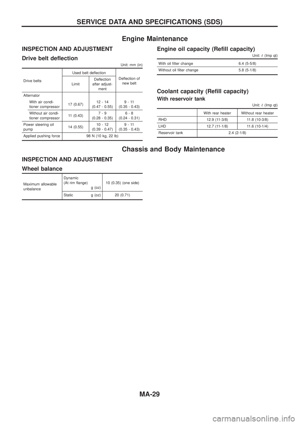
Engine Maintenance
INSPECTION AND ADJUSTMENT
Drive belt de¯ection
Unit: mm (in)
Drive beltsUsed belt de¯ection
De¯ection of
new belt
LimitDe¯ection
after adjust-
ment
Alternator
With air condi-
tioner compressor17 (0.67)12-14
(0.47 - 0.55)9-11
(0.35 - 0.43)
Without air condi-
tioner compressor11 (0.43)7-9
(0.28 - 0.35)6-8
(0.24 - 0.31)
Power steering oil
pump14 (0.55)10-12
(0.39 - 0.47)9-11
(0.35 - 0.43)
Applied pushing force 98 N (10 kg, 22 lb)
Engine oil capacity (Re®ll capacity)
Unit:!(Imp qt)
With oil ®lter change 6.4 (5-5/8)
Without oil ®lter change 5.8 (5-1/8)
Coolant capacity (Re®ll capacity)
With reservoir tank
Unit:!(Imp qt)
With rear heater Without rear heater
RHD 12.9 (11-3/8) 11.8 (10-3/8)
LHD 12.7 (11-1/8) 11.6 (10-1/4)
Reservoir tank 2.4 (2-1/8)
Chassis and Body Maintenance
INSPECTION AND ADJUSTMENT
Wheel balance
Maximum allowable
unbalanceDynamic
(At rim ¯ange)
g (oz)10 (0.35) (one side)
Static g (oz) 20 (0.71)
SERVICE DATA AND SPECIFICATIONS (SDS)
MA-29
Page 1007 of 1226
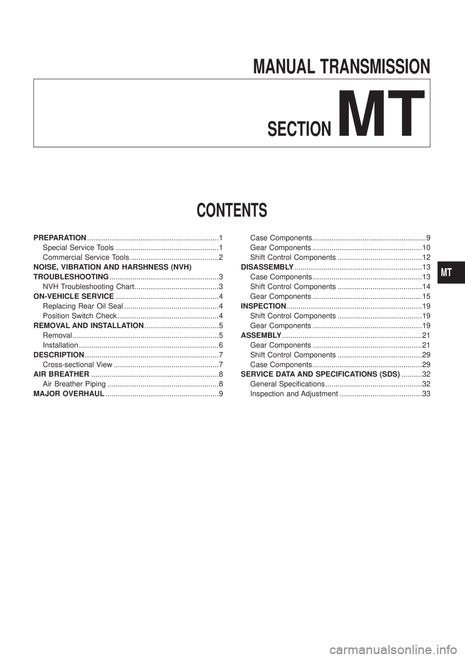
MANUAL TRANSMISSION
SECTION
MT
CONTENTS
PREPARATION................................................................1
Special Service Tools ..................................................1
Commercial Service Tools ...........................................2
NOISE, VIBRATION AND HARSHNESS (NVH)
TROUBLESHOOTING.....................................................3
NVH Troubleshooting Chart.........................................3
ON-VEHICLE SERVICE..................................................4
Replacing Rear Oil Seal ..............................................4
Position Switch Check .................................................4
REMOVAL AND INSTALLATION....................................5
Removal .......................................................................5
Installation ....................................................................6
DESCRIPTION.................................................................7
Cross-sectional View ...................................................7
AIR BREATHER..............................................................8
Air Breather Piping ......................................................8
MAJOR OVERHAUL.......................................................9Case Components .......................................................9
Gear Components .....................................................10
Shift Control Components .........................................12
DISASSEMBLY..............................................................13
Case Components .....................................................13
Shift Control Components .........................................14
Gear Components .....................................................15
INSPECTION..................................................................19
Shift Control Components .........................................19
Gear Components .....................................................19
ASSEMBLY....................................................................21
Gear Components .....................................................21
Shift Control Components .........................................29
Case Components .....................................................29
SERVICE DATA AND SPECIFICATIONS (SDS)..........32
General Speci®cations ...............................................32
Inspection and Adjustment ........................................33
MT
Page 1039 of 1226
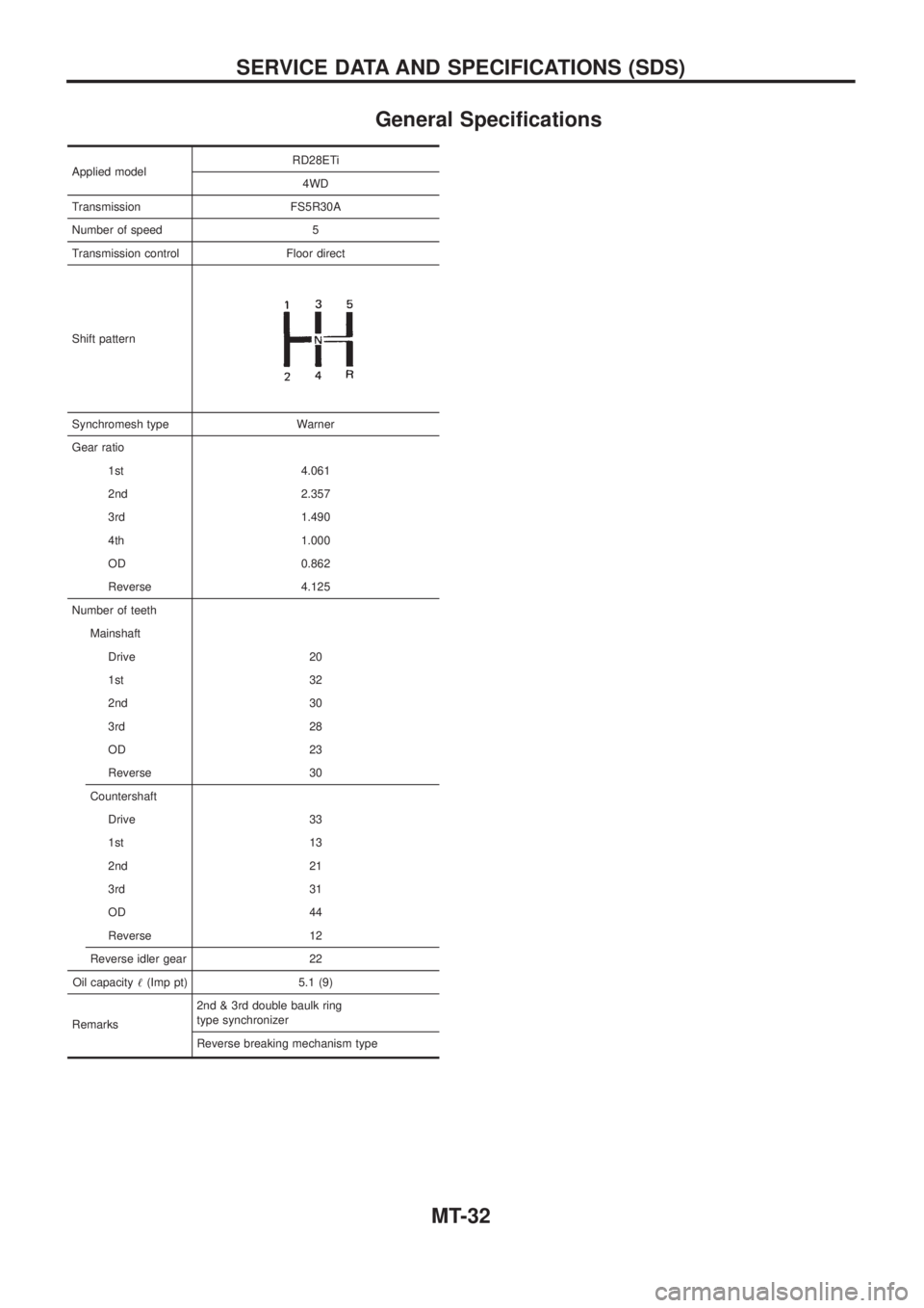
General Speci®cations
Applied modelRD28ETi
4WD
Transmission FS5R30A
Number of speed 5
Transmission control Floor direct
Shift pattern
Synchromesh type Warner
Gear ratio
1st 4.061
2nd 2.357
3rd 1.490
4th 1.000
OD 0.862
Reverse 4.125
Number of teeth
Mainshaft
Drive 20
1st 32
2nd 30
3rd 28
OD 23
Reverse 30
Countershaft
Drive 33
1st 13
2nd 21
3rd 31
OD 44
Reverse 12
Reverse idler gear 22
Oil capacity!(Imp pt) 5.1 (9)
Remarks2nd & 3rd double baulk ring
type synchronizer
Reverse breaking mechanism type
SERVICE DATA AND SPECIFICATIONS (SDS)
MT-32