Page 33 of 1226
Removal
1. Disconnect harness connector.
2. Disconnect control cable from control lever and bracket.
3. Remove control lever and bracket.
4. Disconnect control cable from center brake and remove controlcable.
Inspection
1. Check control lever and ratchet for evidence of wear or otherdamage. Replace if necessary.
2. Check wires for evidence of discontinuity or other deterioration. Replace if necessary.
3. Check parts at each connection for deformation or damage. Replace if necessary.
4. Check warning lamp and switch. Replace if necessary.
SBR437A
SBR209E
PARKING CENTER BRAKE CONTROL
BR-29
Page 34 of 1226
Installation
1. Apply a coating of grease to sliding contact surfaces.
2. Insert clevis pin from left side.
3. After installation is completed, adjust entire system.
Adjustment
1. Pull control lever with speci®ed amount of force. Check leverstroke and ensure smooth operation.Number of notches :7-9
2. Bend parking brake warning lamp switchplate so that brake warning lamp comes on when ratchet at parking brake lever is
pulled notches and goes out when fully released.Number of notches: 2
SBR033A
SBR438A
PARKING CENTER BRAKE CONTROL
BR-30
Page 35 of 1226
Removal and Installation
WARNING:
Clean brake lining with a vacuum dust collector to minimize
the hazard of airborne particles or other materials.
CAUTION:
Make sure parking brake lever is released completely.
1. Release parking brake lever fully.
2. Remove rear propeller shaft and drum.
3. After removing shoe hold pin by rotating push retainer, removeleading shoe then remove trailing shoe.
Remove spring by rotating shoes in direction arrow.
4. Remove adjuster and return spring.
5. Disconnect parking brake cable from center brake lever.
Be careful not to damage parking brake cable when separat-
ing it.
6. Remove retainer ring with a suitable tool. Then separate cen- ter brake lever and brake shoe.
SBR251E
SBR180E
PARKING CENTER BRAKE
BR-31
Page 37 of 1226

Purpose
The Anti-Lock Brake System (ABS) consists of electronic and hydraulic components. It allows for control of
braking force so locking of the wheels can be avoided.
The ABS:
1) Improves proper tracking performance through steering wheel operation.
2) Eases obstacle avoidance through steering wheel operation.
3) Improves vehicle stability.
Operation
+When the vehicle speed is less than 10 km/h (6 MPH) this system does not work.
+ The Anti-Lock Brake System (ABS) has a self-test function. The system turns on the ABS warning lamp
for 1 second each time the ignition switch is turned ``ON''. After the engine is started, the ABS warning
lamp turns off. The system performs a test the ®rst time the vehicle reaches 6 km/h (4 MPH). A mechani-
cal noise may be heard as the ABS performs this self-test. This is a normal part of the self-test feature. If
a malfunction is found during this check, the ABS warning lamp will stay on.
+ While driving, a mechanical noise may be heard during ABS operation. This is a normal condition.
+ While DIFF-LOCK is on, the anti-lock brake warning light ¯ashes. This indicates that anti-lock may not be
fully operated. (ABS only)
ABS Hydraulic Circuit
j1Inlet solenoid valve
j
2Outlet solenoid valve
j
3Reservoir j
4Pump
j
5Motor
j
6Inlet valve j
7Outlet valve
j
8Bypass check valve
j
9Damper
SBR211E
ANTI-LOCK BRAKE SYSTEM
BR-33
Page 38 of 1226

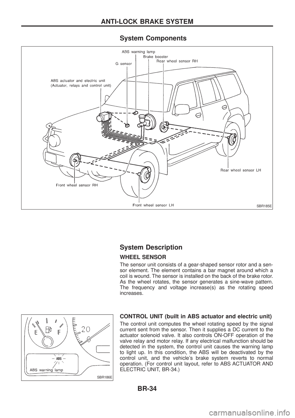
System Components
System Description
WHEEL SENSOR
The sensor unit consists of a gear-shaped sensor rotor and a sen-
sor element. The element contains a bar magnet around which a
coil is wound. The sensor is installed on the back of the brake rotor.
As the wheel rotates, the sensor generates a sine-wave pattern.
The frequency and voltage increase(s) as the rotating speed
increases.
CONTROL UNIT (built in ABS actuator and electric unit)
The control unit computes the wheel rotating speed by the signal
current sent from the sensor. Then it supplies a DC current to the
actuator solenoid valve. It also controls ON-OFF operation of the
valve relay and motor relay. If any electrical malfunction should be
detected in the system, the control unit causes the warning lamp
to light up. In this condition, the ABS will be deactivated by the
control unit, and the vehicle's brake system reverts to normal
operation. (For control unit layout, refer to ABS ACTUATOR AND
ELECTRIC UNIT, BR-34.)
SBR185E
SBR186E
ANTI-LOCK BRAKE SYSTEM
BR-34
Page 44 of 1226

Preliminary Check
Check brake ¯uid level in reservoir
tank.
- ---------------------------------------------------------------------------------------------------------------------------------------------------------------------------------------------------------------------------------------------------------------------------------------------------------------
Low ¯uid level may indicate brake pad
wear or leakage from brake line.
Check brake line for leakage.
OKcNG Repair.
b
Check brake booster for operation and air
tightness. Refer to BR-15.
OK
cNGReplace.
b
Check brake pads and rotor. Refer to
BR-21, 25.
OK
cNGReplace.
Check brake ¯uid level in reservoir tank
again.
OK
cNGFill up brake ¯uid.
Check warning lamp activation.
When ignition switch is turned on, warning
lamp turns on.
OK
cNG
Check fuse, warning lamp
bulb and warning lamp cir-
cuit.
Check warning lamp for deactivation after
engine is started.
OK
cNGGo to Self-diagnosis,
BR-46, 50.
Drive vehicle at speeds over 30 km/h (19
MPH) for at least 1 minute.
Ensure warning lamp remains off while
driving.
OK
cNGGo to Self-diagnosis,
BR-46, 50.
END
SBR451D
SBR389C
SBR058C
SBR059C
SBR186E
.
.
.
.
.
.
.
.
.
TROUBLE DIAGNOSES
BR-40
Page 51 of 1226

Self-diagnosis
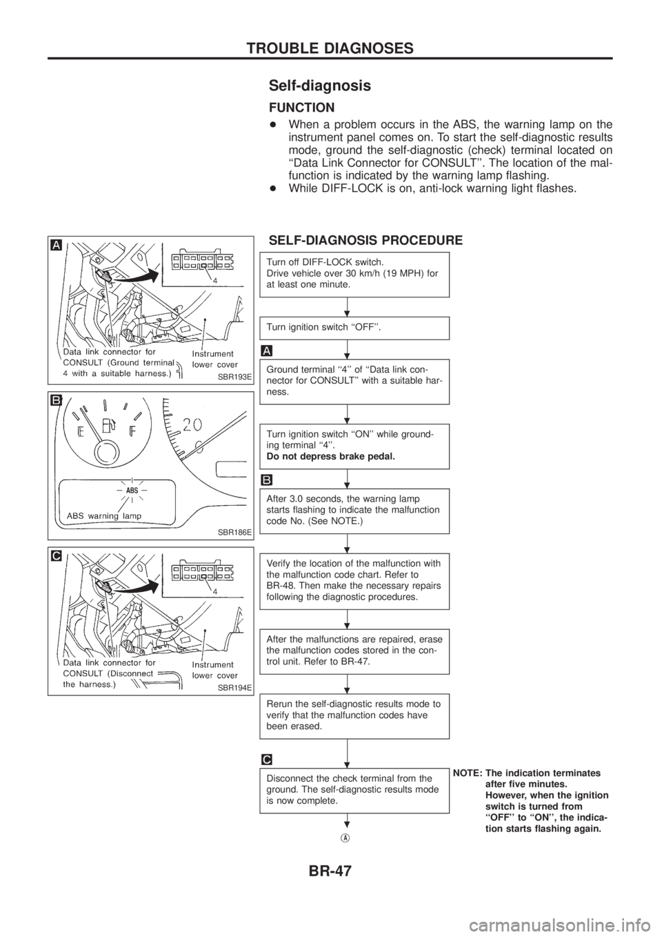
FUNCTION
+When a problem occurs in the ABS, the warning lamp on the
instrument panel comes on. To start the self-diagnostic results
mode, ground the self-diagnostic (check) terminal located on
``Data Link Connector for CONSULT''. The location of the mal-
function is indicated by the warning lamp ¯ashing.
+ While DIFF-LOCK is on, anti-lock warning light ¯ashes.
SELF-DIAGNOSIS PROCEDURE
Turn off DIFF-LOCK switch.
Drive vehicle over 30 km/h (19 MPH) for
at least one minute.
Turn ignition switch ``OFF''.
Ground terminal ``4'' of ``Data link con-
nector for CONSULT'' with a suitable har-
ness.
Turn ignition switch ``ON'' while ground-
ing terminal ``4''.
Do not depress brake pedal.
After 3.0 seconds, the warning lamp
starts ¯ashing to indicate the malfunction
code No. (See NOTE.)
Verify the location of the malfunction with
the malfunction code chart. Refer to
BR-48. Then make the necessary repairs
following the diagnostic procedures.
After the malfunctions are repaired, erase
the malfunction codes stored in the con-
trol unit. Refer to BR-47.
Rerun the self-diagnostic results mode to
verify that the malfunction codes have
been erased.
Disconnect the check terminal from the
ground. The self-diagnostic results mode
is now complete.NOTE: The indication terminates
after ®ve minutes.
However, when the ignition
switch is turned from
``OFF'' to ``ON'', the indica-
tion starts ¯ashing again.
j
A
SBR193E
SBR186E
SBR194E
.
.
.
.
.
.
.
.
.
TROUBLE DIAGNOSES
BR-47
Page 52 of 1226

jA
Check warning lamp for deactivation after
driving vehicle over 30 km/h (19 MPH)
for at least one minute.
After making certain that warning lamp
does not come on, test the ABS in a safe
area to verify that it functions properly.
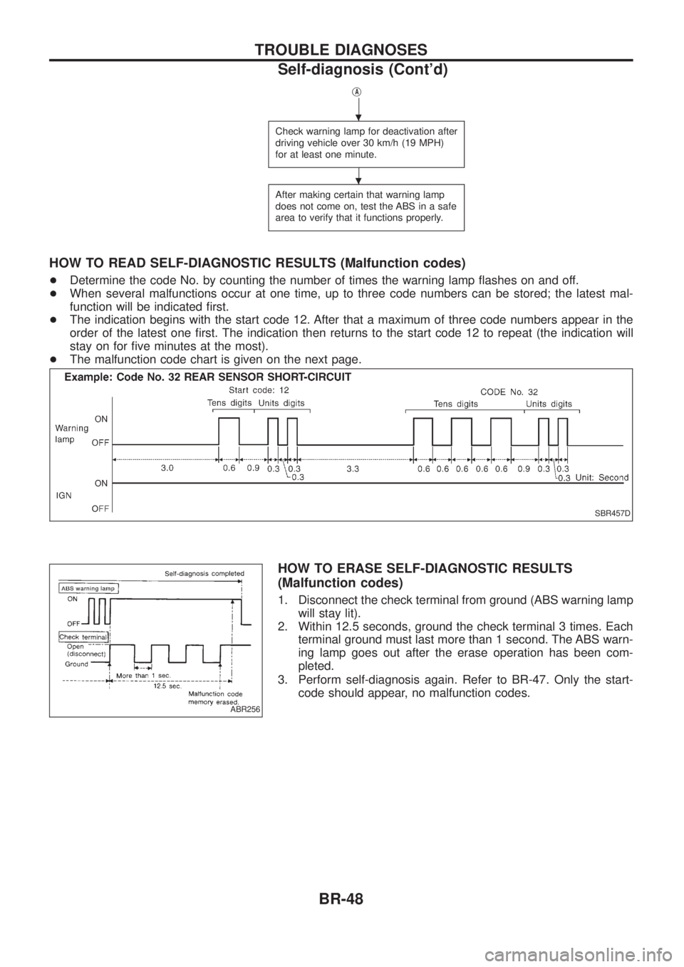
HOW TO READ SELF-DIAGNOSTIC RESULTS (Malfunction codes)
+Determine the code No. by counting the number of times the warning lamp ¯ashes on and off.
+ When several malfunctions occur at one time, up to three code numbers can be stored; the latest mal-
function will be indicated ®rst.
+ The indication begins with the start code 12. After that a maximum of three code numbers appear in the
order of the latest one ®rst. The indication then returns to the start code 12 to repeat (the indication will
stay on for ®ve minutes at the most).
+ The malfunction code chart is given on the next page.
HOW TO ERASE SELF-DIAGNOSTIC RESULTS
(Malfunction codes)
1. Disconnect the check terminal from ground (ABS warning lamp
will stay lit).
2. Within 12.5 seconds, ground the check terminal 3 times. Each terminal ground must last more than 1 second. The ABS warn-
ing lamp goes out after the erase operation has been com-
pleted.
3. Perform self-diagnosis again. Refer to BR-47. Only the start- code should appear, no malfunction codes.
SBR457D
ABR256
.
.
TROUBLE DIAGNOSES
Self-diagnosis (Cont'd)
BR-48