2006 NISSAN PATROL ESP
[x] Cancel search: ESPPage 2 of 1226
FOREWORD
This manual contains maintenance and repair procedures for NISSAN
PATROL GR,modelY61 series.
In order to assure your safety and the efficient functioning of the vehicle,
this manual should be read thoroughly. It is especially important that the
PRECAUTIONS in the GI section be completely understood before starting
any repair task.
All information in this manual is based on the latest product information
at the time of publication. The right is reserved to make changes in speci-
®cations and methods at any time without notice.
IMPORTANT SAFETY NOTICE
The proper performance of service is essential for both the safety of the
technician and the efficient functioning of the vehicle.
The service methods in this Service Manual are described in such a man-
ner that the service may be performed safely and accurately.
Service varies with the procedures used, the skills of the technician and the
tools and parts available. Accordingly, anyone using service procedures,
tools or parts which are not speci®cally recommended by NISSAN must
®rst completely satisfy himself that neither his safety nor the vehicle's
safety will be jeopardized by the service method selected.
NISSAN EUROPE S.A.S.
Service Engineering SectionParis, France
Page 15 of 1226

1. Loosen lock nut and adjust pedal free height by turning brakebooster input rod. Then tighten lock nut.
Make sure that tip of input rod stays inside.
2. Adjust clearance ``C
1'' and ``C2'' with stop lamp switch and
ASCD switch respectively. Then tighten lock nuts.
3. Check pedal free play.
Make sure that stop lamp is off when pedal is released.
4. Check brake pedal's depressed height while engine is running. If depressed height is below speci®ed value, check brake sys-
tem for leaks, accumulation of air or any damage to compo-
nents (master cylinder, wheel cylinder, etc.). Then make nec-
essary repairs.
SBR824B
BRAKE PEDAL AND BRACKET
Adjustment (Cont'd)
BR-11
Page 43 of 1226
How to Perform Trouble Diagnoses for Quick
and Accurate Repair
INTRODUCTION
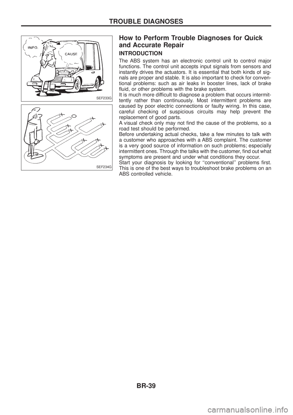
The ABS system has an electronic control unit to control major
functions. The control unit accepts input signals from sensors and
instantly drives the actuators. It is essential that both kinds of sig-
nals are proper and stable. It is also important to check for conven-
tional problems: such as air leaks in booster lines, lack of brake
¯uid, or other problems with the brake system.
It is much more difficult to diagnose a problem that occurs intermit-
tently rather than continuously. Most intermittent problems are
caused by poor electric connections or faulty wiring. In this case,
careful checking of suspicious circuits may help prevent the
replacement of good parts.
A visual check only may not ®nd the cause of the problems, so a
road test should be performed.
Before undertaking actual checks, take a few minutes to talk with
a customer who approaches with a ABS complaint. The customer
is a very good source of information on such problems; especially
intermittent ones. Through the talks with the customer, ®nd out what
symptoms are present and under what conditions they occur.
Start your diagnosis by looking for ``conventional'' problems ®rst.
This is one of the best ways to troubleshoot brake problems on an
ABS controlled vehicle.
SEF233G
SEF234G
TROUBLE DIAGNOSES
BR-39
Page 80 of 1226
Clip and Fastener
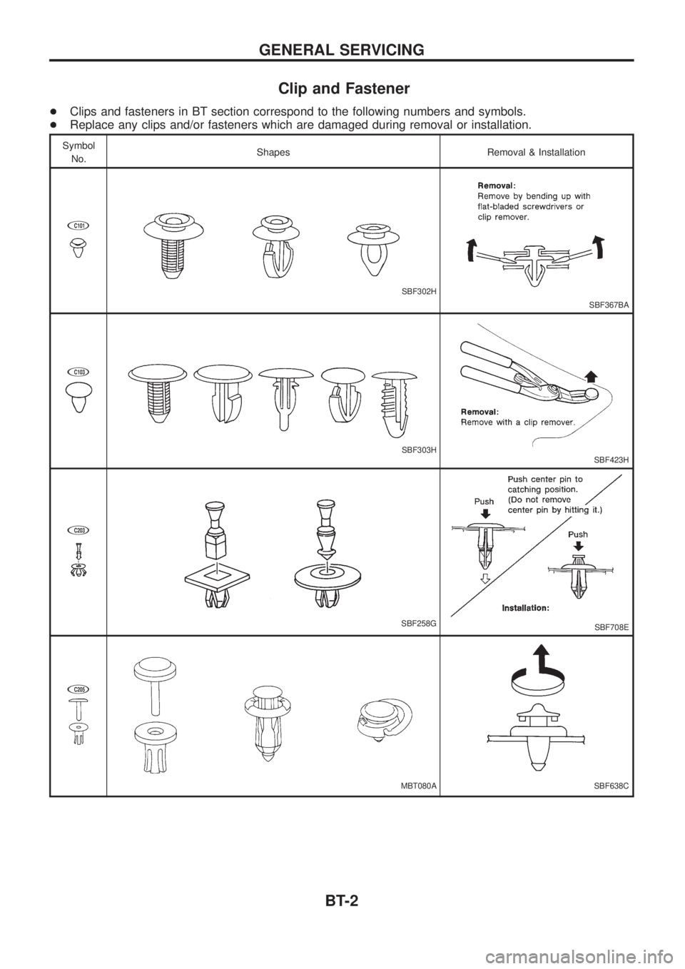
+Clips and fasteners in BT section correspond to the following numbers and symbols.
+Replace any clips and/or fasteners which are damaged during removal or installation.
Symbol
No.Shapes Removal & Installation
jC101
SBF302H
SBF367BA
jC103
SBF303HSBF423H
jC203
SBF258GSBF708E
jC205
MBT080ASBF638C
GENERAL SERVICING
BT-2
Page 150 of 1226
ENGINE CONTROL SYSTEMSECTION
EC
CONTENTS
DIAGNOSTIC TROUBLE CODE INDEX .........................1
Alphabetical & Numerical Index for DTC ....................1
PRECAUTIONS AND PREPARATION ............................2
Special Service Tools ..................................................2
Commercial Service Tool .............................................3
Supplemental Restraint System (SRS) ``AIR
BAG'' and ``SEAT BELT PRE-TENSIONER''...............4
PRECAUTIONS AND PREPARATION ............................5
Engine Fuel & Emission Control System ....................5
Precautions ..................................................................6
ENGINE AND EMISSION CONTROL OVERALL
SYSTEM ........................................................................\
...8
ECCS-D Component Parts Location ...........................8
Circuit Diagram .......................................................... 11
System Diagram ........................................................12
Vacuum Hose Drawing ..............................................13
System Chart .............................................................14
ENGINE AND EMISSION BASIC CONTROL
SYSTEM DESCRIPTION ...............................................15
Fuel Injection System ................................................15
Fuel Injection Timing System ....................................18
Air Conditioning Cut Control ......................................19
Fuel Cut Control (at no load & high engine
speed) ........................................................................\
20
CRANKCASE VENTILATION SYSTEM ........................21
Description .................................................................21
Inspection...................................................................21
INJECTION NOZZLE .....................................................22
Removal and Installation ...........................................22
Disassembly (No. 2 - 4 nozzles) ...............................22
Inspection (No. 2 - 4 nozzles) ...................................23
Cleaning (No. 2 - 4 nozzles) .....................................23
Assembly (No. 2 - 4 nozzles) ....................................24
Test and Adjustment ..................................................25
ELECTRONIC FUEL INJECTION PUMP ......................27
Removal .....................................................................27
Installation ..................................................................28
Disassembly and Assembly .......................................29
ON BOARD DIAGNOSTIC SYSTEM
DESCRIPTION ...............................................................30
DTC and MIL Detection Logic ...................................30
Diagnostic Trouble Code (DTC) ................................30 Malfunction Indicator Lamp (MIL) ..............................31
CONSULT ..................................................................36
TROUBLE DIAGNOSIS Ð Introduction ......................42
Introduction ................................................................42
Diagnostic Worksheet ................................................43
TROUBLE DIAGNOSIS Ð Work Flow ........................44
Work Flow ..................................................................44
Description for Work Flow .........................................45
TROUBLE DIAGNOSIS Ð Basic Inspection ..............46
Basic Inspection.........................................................46
TROUBLE DIAGNOSIS Ð General Description ........48
Symptom Matrix Chart ...............................................48
CONSULT Reference Value in Data Monitor
Mode ........................................................................\
..51
Major Sensor Reference Graph in Data Monitor
Mode ........................................................................\
..53
ECM Terminals and Reference Value .......................54
TROUBLEDIAGNOSISFORPOWERSUPPLY ..........63
MainPowerSupplyandGroundCircuit....................63
TROUBLE DIAGNOSIS FOR ``CAM POS SEN
(PUMP)''(DTC11) .........................................................69
CamshaftPositionSensor(CMPS)(PUMP).............69
TROUBLEDIAGNOSISFOR``MASSAIRFLOW
SEN''(DTC12) ..............................................................74
MassAirFlowSensor(MAFS)..................................74
TROUBLEDIAGNOSISFOR``COOLANTTEMP
SEN''(DTC13) ..............................................................79
EngineCoolantTemperature(ECT)Sensor.............79
TROUBLEDIAGNOSISFOR``VEHICLESPEED
SEN''(DTC14) ..............................................................83
VehicleSpeedSensor(VSS)....................................83
TROUBLEDIAGNOSISFOR``CONTSLEEVPOS
SEN''(DTC15) ..............................................................87
ControlSleevePositionSensor(CSPS)...................87
TROUBLEDIAGNOSISFOR``ADJUST
RESISTOR''(DTC17) ...................................................92
AdjustmentResistor...................................................92
TROUBLEDIAGNOSISFOR``F/INJF/B2''
(DTC18),``F/INJF/B''(DTC22),``ELECTRIC
GOV''(DTC25) ..............................................................96
ElectricGovernor.......................................................96
EC
Page 167 of 1226
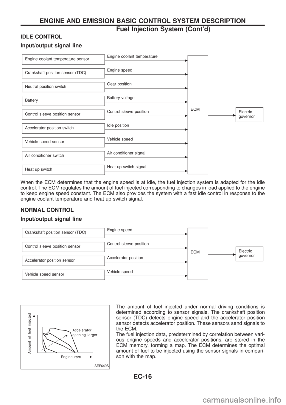
IDLE CONTROL
Input/output signal line
Engine coolant temperature sensorcEngine coolant temperature
ECM
cElectric
governor
Crankshaft position sensor (TDC)cEngine speed
Neutral position switch
cGear position
Battery
cBattery voltage
Control sleeve position sensor
cControl sleeve position
Accelerator position switch
cIdle position
Vehicle speed sensor
cVehicle speed
Air conditioner switch
cAir conditioner signal
Heat up switch
cHeat up switch signal
When the ECM determines that the engine speed is at idle, the fuel injection system is adapted for the idle
control. The ECM regulates the amount of fuel injected corresponding to changes in load applied to the engine
to keep engine speed constant. The ECM also provides the system with a fast idle control in response to the
engine coolant temperature and heat up switch signal.
NORMAL CONTROL
Input/output signal line
Crankshaft position sensor (TDC)cEngine speed
ECM
cElectric
governorControl sleeve position sensorcControl sleeve position
Accelerator position sensor
cAccelerator position
Vehicle speed sensor
cVehicle speed
The amount of fuel injected under normal driving conditions is
determined according to sensor signals. The crankshaft position
sensor (TDC) detects engine speed and the accelerator position
sensor detects accelerator position. These sensors send signals to
the ECM.
The fuel injection data, predetermined by correlation between vari-
ous engine speeds and accelerator positions, are stored in the
ECM memory, forming a map. The ECM determines the optimal
amount of fuel to be injected using the sensor signals in compari-
son with the map.
SEF649S
ENGINE AND EMISSION BASIC CONTROL SYSTEM DESCRIPTION
Fuel Injection System (Cont'd)
EC-16
Page 176 of 1226
Test and Adjustment
WARNING:
When using nozzle tester, be careful not to allow diesel fuel
sprayed from nozzle to contact your hands or body, and make
sure your eyes are properly protected with goggles.
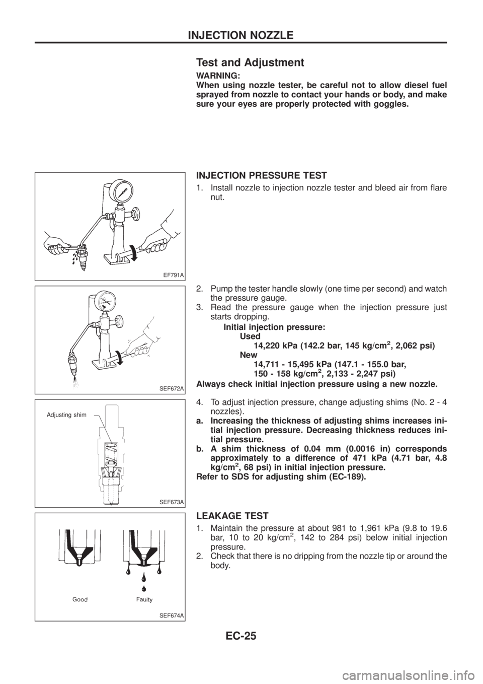
INJECTION PRESSURE TEST
1. Install nozzle to injection nozzle tester and bleed air from ¯are
nut.
2. Pump the tester handle slowly (one time per second) and watch
the pressure gauge.
3. Read the pressure gauge when the injection pressure just
starts dropping.
Initial injection pressure:
Used
14,220 kPa (142.2 bar, 145 kg/cm
2, 2,062 psi)
New
14,711 - 15,495 kPa (147.1 - 155.0 bar,
150 - 158 kg/cm
2, 2,133 - 2,247 psi)
Always check initial injection pressure using a new nozzle.
4. To adjust injection pressure, change adjusting shims (No. 2 - 4
nozzles).
a. Increasing the thickness of adjusting shims increases ini-
tial injection pressure. Decreasing thickness reduces ini-
tial pressure.
b. A shim thickness of 0.04 mm (0.0016 in) corresponds
approximately to a difference of 471 kPa (4.71 bar, 4.8
kg/cm
2, 68 psi) in initial injection pressure.
Refer to SDS for adjusting shim (EC-189).
LEAKAGE TEST
1. Maintain the pressure at about 981 to 1,961 kPa (9.8 to 19.6
bar, 10 to 20 kg/cm2, 142 to 284 psi) below initial injection
pressure.
2. Check that there is no dripping from the nozzle tip or around the
body.
EF791A
SEF672A
SEF673A
Adjusting shim
SEF674A
INJECTION NOZZLE
EC-25
Page 192 of 1226
REAL TIME DIAGNOSIS IN DATA MONITOR MODE
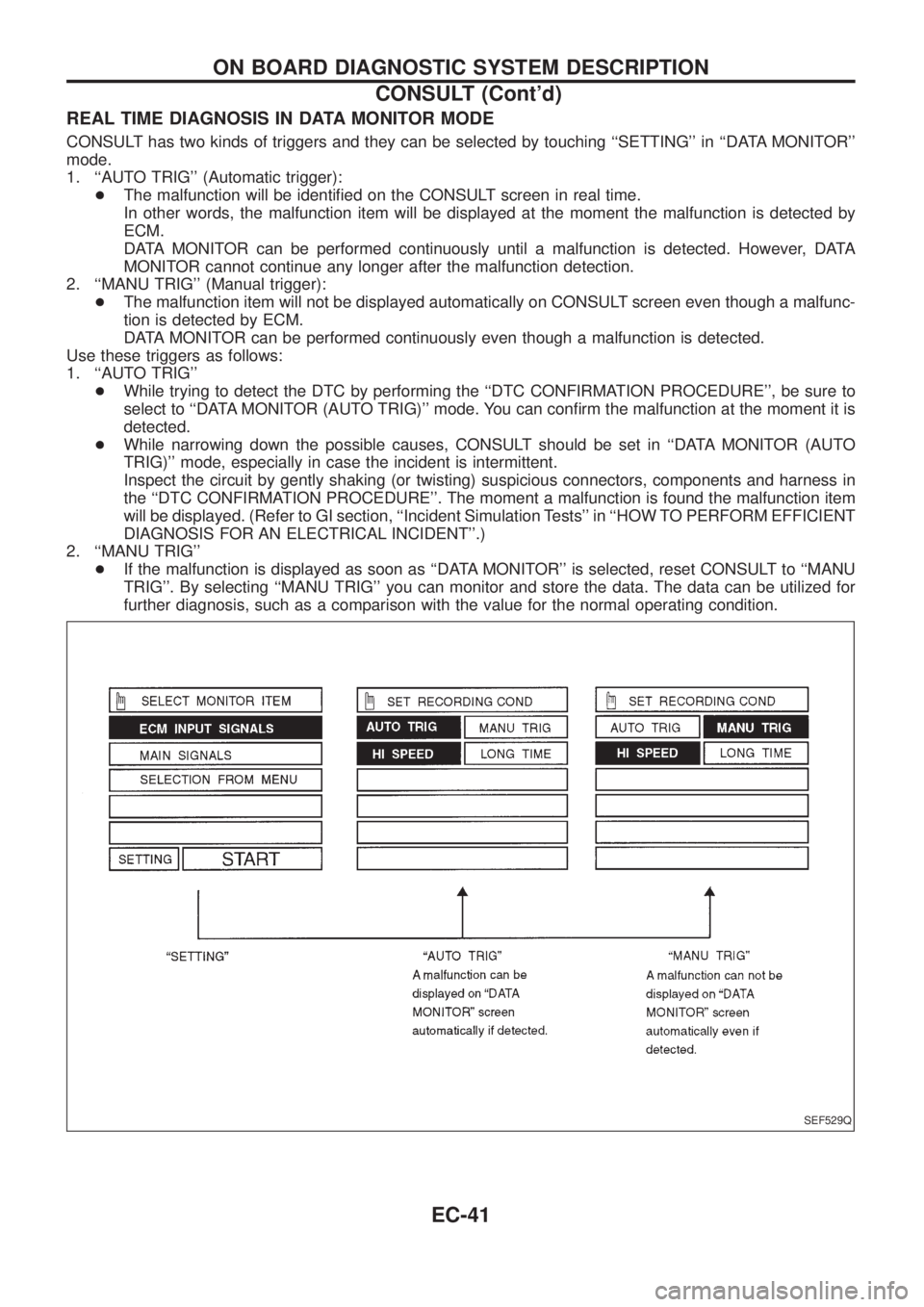
CONSULT has two kinds of triggers and they can be selected by touching ``SETTING'' in ``DATA MONITOR''
mode.
1. ``AUTO TRIG'' (Automatic trigger):
+The malfunction will be identi®ed on the CONSULT screen in real time.
In other words, the malfunction item will be displayed at the moment the malfunction is detected by
ECM.
DATA MONITOR can be performed continuously until a malfunction is detected. However, DATA
MONITOR cannot continue any longer after the malfunction detection.
2. ``MANU TRIG'' (Manual trigger):
+The malfunction item will not be displayed automatically on CONSULT screen even though a malfunc-
tion is detected by ECM.
DATA MONITOR can be performed continuously even though a malfunction is detected.
Use these triggers as follows:
1. ``AUTO TRIG''
+While trying to detect the DTC by performing the ``DTC CONFIRMATION PROCEDURE'', be sure to
select to ``DATA MONITOR (AUTO TRIG)'' mode. You can con®rm the malfunction at the moment it is
detected.
+While narrowing down the possible causes, CONSULT should be set in ``DATA MONITOR (AUTO
TRIG)'' mode, especially in case the incident is intermittent.
Inspect the circuit by gently shaking (or twisting) suspicious connectors, components and harness in
the ``DTC CONFIRMATION PROCEDURE''. The moment a malfunction is found the malfunction item
will be displayed. (Refer to GI section, ``Incident Simulation Tests'' in ``HOW TO PERFORM EFFICIENT
DIAGNOSIS FOR AN ELECTRICAL INCIDENT''.)
2. ``MANU TRIG''
+If the malfunction is displayed as soon as ``DATA MONITOR'' is selected, reset CONSULT to ``MANU
TRIG''. By selecting ``MANU TRIG'' you can monitor and store the data. The data can be utilized for
further diagnosis, such as a comparison with the value for the normal operating condition.
SEF529Q
ON BOARD DIAGNOSTIC SYSTEM DESCRIPTION
CONSULT (Cont'd)
EC-41