2006 NISSAN PATROL warning
[x] Cancel search: warningPage 75 of 1226
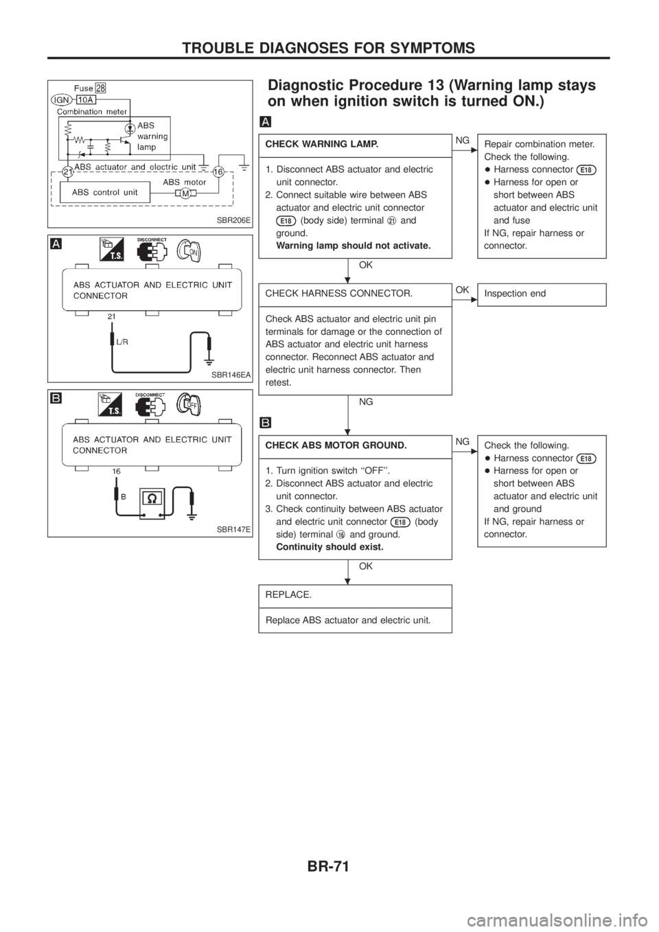
Diagnostic Procedure 13 (Warning lamp stays
on when ignition switch is turned ON.)
CHECK WARNING LAMP.
- ---------------------------------------------------------------------------------------------------------------------------------------------------------------------------------------------------------------------------------------------------------------------------------------------------------------
1. Disconnect ABS actuator and electric unit connector.
2. Connect suitable wire between ABS actuator and electric unit connector
E18(body side) terminal j21and
ground.
Warning lamp should not activate.
OK
cNG Repair combination meter.
Check the following.
+Harness connector
E18
+Harness for open or
short between ABS
actuator and electric unit
and fuse
If NG, repair harness or
connector.
CHECK HARNESS CONNECTOR.
- ---------------------------------------------------------------------------------------------------------------------------------------------------------------------------------------------------------------------------------------------------------------------------------------------------------------
Check ABS actuator and electric unit pin
terminals for damage or the connection of
ABS actuator and electric unit harness
connector. Reconnect ABS actuator and
electric unit harness connector. Then
retest.
NG
cOK Inspection end
CHECK ABS MOTOR GROUND.
- ---------------------------------------------------------------------------------------------------------------------------------------------------------------------------------------------------------------------------------------------------------------------------------------------------------------
1. Turn ignition switch ``OFF''.
2. Disconnect ABS actuator and electric unit connector.
3. Check continuity between ABS actuator and electric unit connector
E18(body
side) terminal j
16and ground.
Continuity should exist.
OK
cNG Check the following.
+Harness connector
E18
+Harness for open or
short between ABS
actuator and electric unit
and ground
If NG, repair harness or
connector.
REPLACE.
- ---------------------------------------------------------------------------------------------------------------------------------------------------------------------------------------------------------------------------------------------------------------------------------------------------------------
Replace ABS actuator and electric unit.
SBR206E
SBR146EA
SBR147E
.
.
.
TROUBLE DIAGNOSES FOR SYMPTOMS
BR-71
Page 77 of 1226
Inspection and Adjustment
DISC BRAKE
Unit: mm (in)
Brake model CL36VE CL18VF
Pad wear limit
Minimum thickness 2.0 (0.079)
Rotor repair limit
Minimum thickness 30.0 (1.181) 16.0 (0.630)
PARKING CENTER BRAKE
Unit: mm (in)
Brake model DS20HB
Lining wear limit
Minimum thickness 1.5 (0.059)
Drum repair limit
Maximum inner diameter 204.5 (8.05)
BRAKE PEDAL
Unit: mm (in)
Applied model M/T
Free height ``H''*184 - 194
(7.24 - 7.64)
Depressed height ``D''
[under force of 490 N (50
kg, 110 lb) with engine run-
ning]More than
80 (3.15)
Clearance ``C'' between
pedal stopper and threaded
end of stop lamp switch or
ASCD switch0.3 - 1.0 (0.012 - 0.039)
Pedal free play
At clevis 1.0 - 3.0 (0.039 - 0.118)
At pedal pad 3.0 - 11.0 (0.118 - 0.433)
*: Measured from surface of melt sheet to pedal pad.
PARKING CENTER BRAKE CONTROL
Control type Center lever
Lever stroke
[under force of 196 N (20 kg, 44 lb)]7-9
Lever stroke when warning switch comes on 2
SERVICE DATA AND SPECIFICATIONS (SDS)
BR-73
Page 79 of 1226

Service Notice
+When removing or installing various parts, place a cloth or padding onto the vehicle body to prevent
scratches.
+Handle trim, molding, instruments, grille, etc. carefully during removing or installing. Be careful not to soil
or damage them.
+Apply sealing compound where necessary when installing parts.
+When applying sealing compound, be careful that the sealing compound does not protrude from parts.
+When replacing any metal parts (for example body outer panel, members, etc.), be sure to take rust pre-
vention measures.
Supplemental Restraint System (SRS) ``AIR
BAG'' and ``SEAT BELT PRE-TENSIONER''
The Supplemental Restraint System such as ``AIR BAG'' and ``SEAT BELT PRE-TENSIONER'' used along with
a seat belt, helps to reduce the risk or severity of injury to the driver and front passenger in a frontal collision.
The SRS system composition which is available to NISSAN MODEL Y61 is as follows (The composition var-
ies according to the destination.):
Driver air bag module (located in the center of the steering wheel), front passenger air bag module (located
on the instrument panel on passenger side), seat belt pre-tensioner, a diagnosis sensor unit, warning lamp,
wiring harness and spiral cable.
Information necessary to service the system safely is included in theRS sectionof this Service Manual.
WARNING:
+To avoid rendering the SRS inoperative, which could increase the risk of personal injury or death
in the event of a collision which would result in air bag in¯ation, all maintenance must be performed
by an authorized NISSAN dealer.
+Improper maintenance, including incorrect removal and installation of the SRS, can lead to per-
sonal injury caused by unintentional activation of the system. For removal of Spiral Cable and Air
Bag Module, see the RS section.
+Do not use electrical test equipment on any circuit related to the SRS unless instructed to in this
Service Manual. Spiral cable and wiring harnesses covered with yellow insulation either just before
the harness connectors or for the complete harness are related to the SRS.
PRECAUTIONS
BT-1
Page 84 of 1226
Body Rear End and Opener
+Bumper fascia is made of plastic. Do not use excessive force and be sure to keep oil away from it.
+Back door lock system adjustment: Adjust lock & striker so that they are in the center.
After adjustment, check back door lock operation.
+Back door hatch lock system adjustment: Adjust lock & striker so that they are in the center.
After adjustment, check back door hatch lock operation.
+Opener cable: Do not attempt to bend cable using excessive force.
+After installation, make sure that back door and fuel ®ller lid open smoothly.
WARNING:
+Be careful not to scratch back door stay and/or back door hatch stay when installing back door
and/or back door hatch. A scratched stay may cause gas leakage.
+The contents of the back door stay and back door hatch stay are under pressure. Do not take apart,
puncture, apply heat or allow ®re near them.
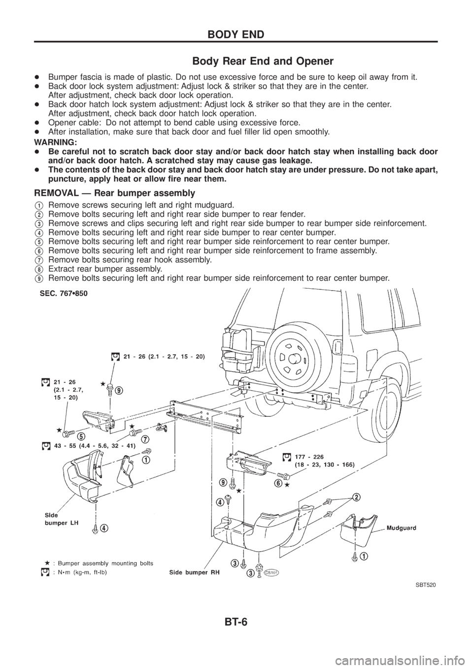
REMOVAL Ð Rear bumper assembly
V1Remove screws securing left and right mudguard.
V2Remove bolts securing left and right rear side bumper to rear fender.
V3Remove screws and clips securing left and right rear side bumper to rear bumper side reinforcement.
V4Remove bolts securing left and right rear side bumper to rear center bumper.
V5Remove bolts securing left and right rear bumper side reinforcement to rear center bumper.
V6Remove bolts securing left and right rear bumper side reinforcement to frame assembly.
V7Remove bolts securing rear hook assembly.
V8Extract rear bumper assembly.
V9Remove bolts securing left and right rear bumper side reinforcement to rear center bumper.
SBT520
BODY END
BT-6
Page 120 of 1226
REMOVAL
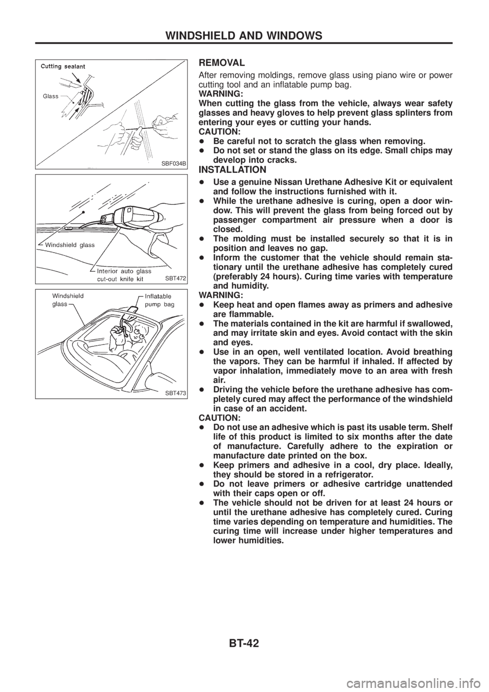
After removing moldings, remove glass using piano wire or power
cutting tool and an in¯atable pump bag.
WARNING:
When cutting the glass from the vehicle, always wear safety
glasses and heavy gloves to help prevent glass splinters from
entering your eyes or cutting your hands.
CAUTION:
+Be careful not to scratch the glass when removing.
+Do not set or stand the glass on its edge. Small chips may
develop into cracks.
INSTALLATION
+Use a genuine Nissan Urethane Adhesive Kit or equivalent
and follow the instructions furnished with it.
+While the urethane adhesive is curing, open a door win-
dow. This will prevent the glass from being forced out by
passenger compartment air pressure when a door is
closed.
+The molding must be installed securely so that it is in
position and leaves no gap.
+Inform the customer that the vehicle should remain sta-
tionary until the urethane adhesive has completely cured
(preferably 24 hours). Curing time varies with temperature
and humidity.
WARNING:
+Keep heat and open ¯ames away as primers and adhesive
are ¯ammable.
+The materials contained in the kit are harmful if swallowed,
and may irritate skin and eyes. Avoid contact with the skin
and eyes.
+Use in an open, well ventilated location. Avoid breathing
the vapors. They can be harmful if inhaled. If affected by
vapor inhalation, immediately move to an area with fresh
air.
+Driving the vehicle before the urethane adhesive has com-
pletely cured may affect the performance of the windshield
in case of an accident.
CAUTION:
+Do not use an adhesive which is past its usable term. Shelf
life of this product is limited to six months after the date
of manufacture. Carefully adhere to the expiration or
manufacture date printed on the box.
+Keep primers and adhesive in a cool, dry place. Ideally,
they should be stored in a refrigerator.
+Do not leave primers or adhesive cartridge unattended
with their caps open or off.
+The vehicle should not be driven for at least 24 hours or
until the urethane adhesive has completely cured. Curing
time varies depending on temperature and humidities. The
curing time will increase under higher temperatures and
lower humidities.
SBF034B
SBT472
SBT473
WINDSHIELD AND WINDOWS
BT-42
Page 134 of 1226
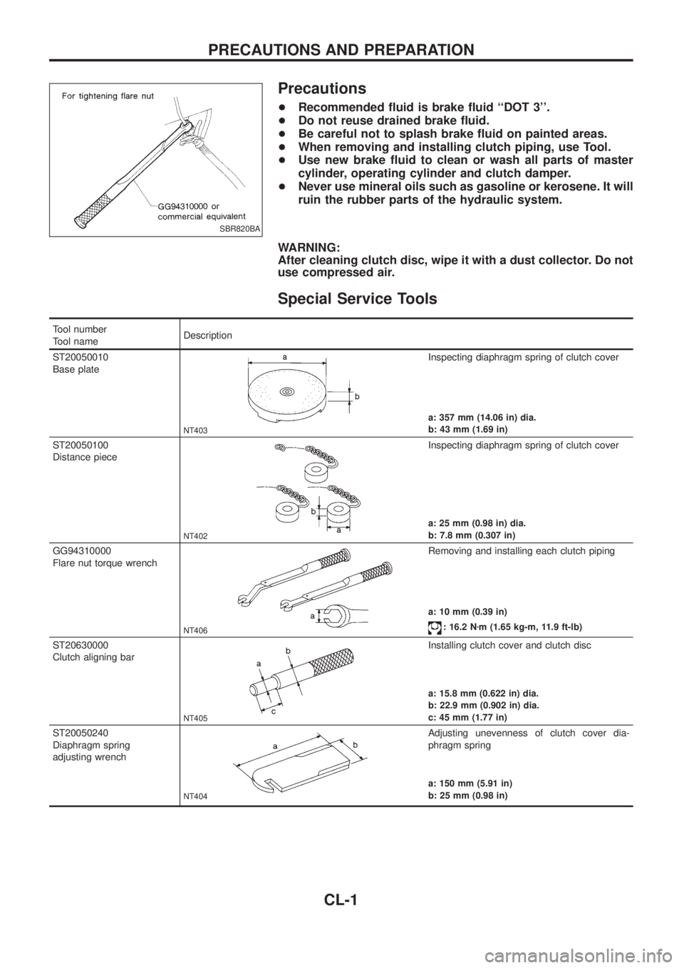
Precautions
+Recommended ¯uid is brake ¯uid ``DOT 3''.
+Do not reuse drained brake ¯uid.
+Be careful not to splash brake ¯uid on painted areas.
+When removing and installing clutch piping, use Tool.
+Use new brake ¯uid to clean or wash all parts of master
cylinder, operating cylinder and clutch damper.
+Never use mineral oils such as gasoline or kerosene. It will
ruin the rubber parts of the hydraulic system.
WARNING:
After cleaning clutch disc, wipe it with a dust collector. Do not
use compressed air.
Special Service Tools
Tool number
Tool nameDescription
ST20050010
Base plate
NT403
Inspecting diaphragm spring of clutch cover
a: 357 mm (14.06 in) dia.
b: 43 mm (1.69 in)
ST20050100
Distance piece
NT402
Inspecting diaphragm spring of clutch cover
a: 25 mm (0.98 in) dia.
b: 7.8 mm (0.307 in)
GG94310000
Flare nut torque wrench
NT406
Removing and installing each clutch piping
a: 10 mm (0.39 in)
: 16.2 Nzm (1.65 kg-m, 11.9 ft-lb)
ST20630000
Clutch aligning bar
NT405
Installing clutch cover and clutch disc
a: 15.8 mm (0.622 in) dia.
b: 22.9 mm (0.902 in) dia.
c: 45 mm (1.77 in)
ST20050240
Diaphragm spring
adjusting wrench
NT404
Adjusting unevenness of clutch cover dia-
phragm spring
a: 150 mm (5.91 in)
b: 25 mm (0.98 in)
SBR820BA
PRECAUTIONS AND PREPARATION
CL-1
Page 155 of 1226
Supplemental Restraint System (SRS) ``AIR
BAG'' and ``SEAT BELT PRE-TENSIONER''
The Supplemental Restraint System such as ``AIR BAG'' and ``SEAT BELT PRE-TENSIONER'' used along with
a seat belt, helps to reduce the risk or severity of injury to the driver and front passenger in a frontal collision.
The SRS system composition which is available to NISSAN MODEL Y61 is as follows (The composition var-
ies according to the destination.):
Driver air bag module (located in the center of the steering wheel), front passenger air bag module (located
on the instrument panel on passenger side), seat belt pre-tensioner, a diagnosis sensor unit, warning lamp,
wiring harness and spiral cable.
Information necessary to service the system safely is included in theRS sectionof this Service Manual.
WARNING:
+To avoid rendering the SRS inoperative, which could increase the risk of personal injury or death
in the event of a collision which would result in air bag in¯ation, all maintenance must be performed
by an authorized NISSAN dealer.
+Improper maintenance, including incorrect removal and installation of the SRS, can lead to per-
sonal injury caused by unintentional activation of the system. For removal of Spiral Cable and Air
Bag Module, see the RS section.
+Do not use electrical test equipment on any circuit related to the SRS unless instructed to in this
Service Manual. Spiral cable and wiring harnesses covered with yellow insulation either just before
the harness connectors or for the complete harness are related to the SRS.
PRECAUTIONS AND PREPARATION
EC-4
Page 176 of 1226
Test and Adjustment
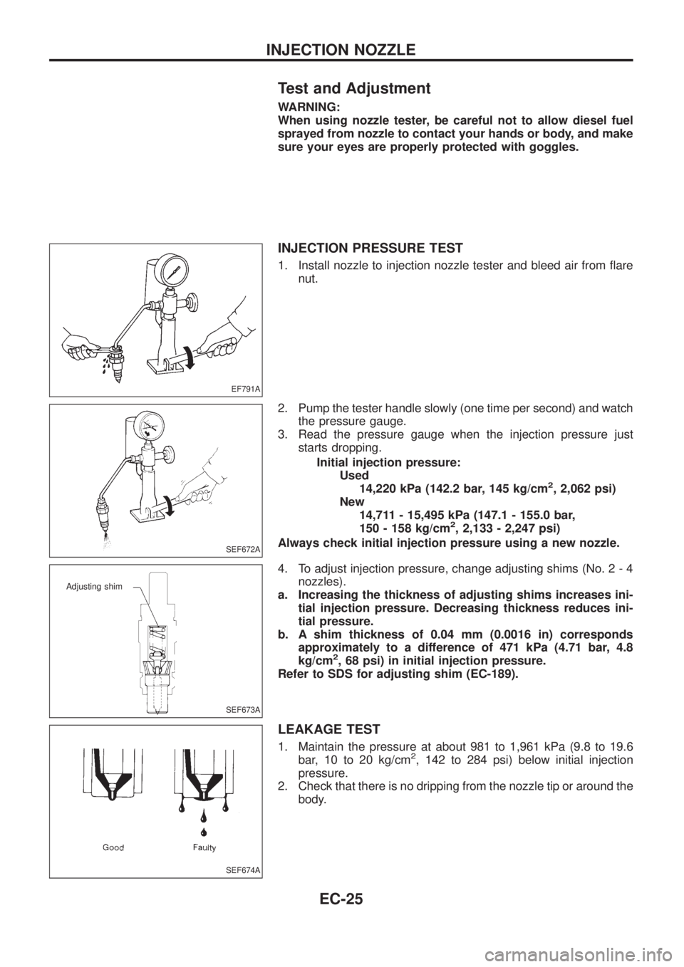
WARNING:
When using nozzle tester, be careful not to allow diesel fuel
sprayed from nozzle to contact your hands or body, and make
sure your eyes are properly protected with goggles.
INJECTION PRESSURE TEST
1. Install nozzle to injection nozzle tester and bleed air from ¯are
nut.
2. Pump the tester handle slowly (one time per second) and watch
the pressure gauge.
3. Read the pressure gauge when the injection pressure just
starts dropping.
Initial injection pressure:
Used
14,220 kPa (142.2 bar, 145 kg/cm
2, 2,062 psi)
New
14,711 - 15,495 kPa (147.1 - 155.0 bar,
150 - 158 kg/cm
2, 2,133 - 2,247 psi)
Always check initial injection pressure using a new nozzle.
4. To adjust injection pressure, change adjusting shims (No. 2 - 4
nozzles).
a. Increasing the thickness of adjusting shims increases ini-
tial injection pressure. Decreasing thickness reduces ini-
tial pressure.
b. A shim thickness of 0.04 mm (0.0016 in) corresponds
approximately to a difference of 471 kPa (4.71 bar, 4.8
kg/cm
2, 68 psi) in initial injection pressure.
Refer to SDS for adjusting shim (EC-189).
LEAKAGE TEST
1. Maintain the pressure at about 981 to 1,961 kPa (9.8 to 19.6
bar, 10 to 20 kg/cm2, 142 to 284 psi) below initial injection
pressure.
2. Check that there is no dripping from the nozzle tip or around the
body.
EF791A
SEF672A
SEF673A
Adjusting shim
SEF674A
INJECTION NOZZLE
EC-25