2006 NISSAN PATROL warning
[x] Cancel search: warningPage 182 of 1226
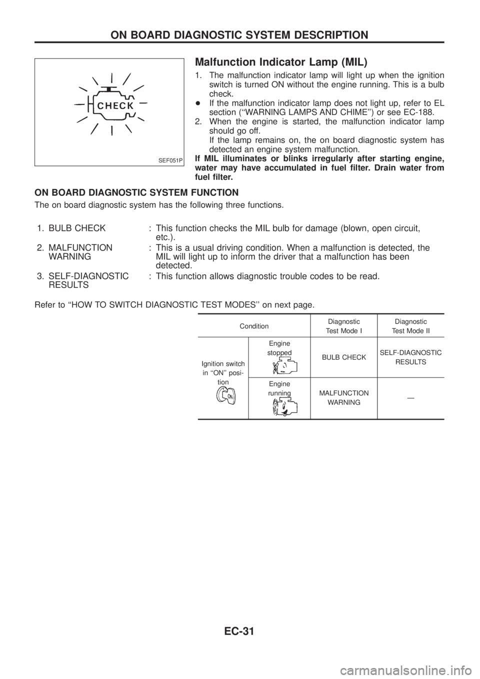
Malfunction Indicator Lamp (MIL)
1. The malfunction indicator lamp will light up when the ignition
switch is turned ON without the engine running. This is a bulb
check.
+If the malfunction indicator lamp does not light up, refer to EL
section (``WARNING LAMPS AND CHIME'') or see EC-188.
2. When the engine is started, the malfunction indicator lamp
should go off.
If the lamp remains on, the on board diagnostic system has
detected an engine system malfunction.
If MIL illuminates or blinks irregularly after starting engine,
water may have accumulated in fuel ®lter. Drain water from
fuel ®lter.
ON BOARD DIAGNOSTIC SYSTEM FUNCTION
The on board diagnostic system has the following three functions.
1. BULB CHECK : This function checks the MIL bulb for damage (blown, open circuit,
etc.).
2. MALFUNCTION
WARNING: This is a usual driving condition. When a malfunction is detected, the
MIL will light up to inform the driver that a malfunction has been
detected.
3. SELF-DIAGNOSTIC
RESULTS: This function allows diagnostic trouble codes to be read.
Refer to ``HOW TO SWITCH DIAGNOSTIC TEST MODES'' on next page.
ConditionDiagnostic
Test Mode IDiagnostic
Test Mode II
Ignition switch
in ``ON'' posi-
tion
Engine
stopped
BULB CHECKSELF-DIAGNOSTIC
RESULTS
Engine
running
MALFUNCTION
WARNINGÐ
SEF051P
ON BOARD DIAGNOSTIC SYSTEM DESCRIPTION
EC-31
Page 185 of 1226
DIAGNOSTIC TEST MODE IÐBULB CHECK
In this mode, the MALFUNCTION INDICATOR LAMP on the instrument panel should stay ON. If it remains
OFF, check the bulb. Refer to EL section (``WARNING LAMPS AND CHIME'') or see EC-188.
DIAGNOSTIC TEST MODE IÐMALFUNCTION WARNING
MALFUNCTION
INDICATOR LAMPCondition
ONWhen the malfunction is detected or the ECM's CPU is malfunctioning. (Refer to ``MIL Illumination'' of the
``DIAGNOSTIC TROUBLE CODE INDEX'', EC-1.)
OFF No malfunction.
+These Diagnostic Trouble Code Numbers are clari®ed in Diagnostic Test Mode II (SELF-DIAGNOSTIC
RESULTS).
DIAGNOSTIC TEST MODE IIÐSELF-DIAGNOSTIC RESULTS
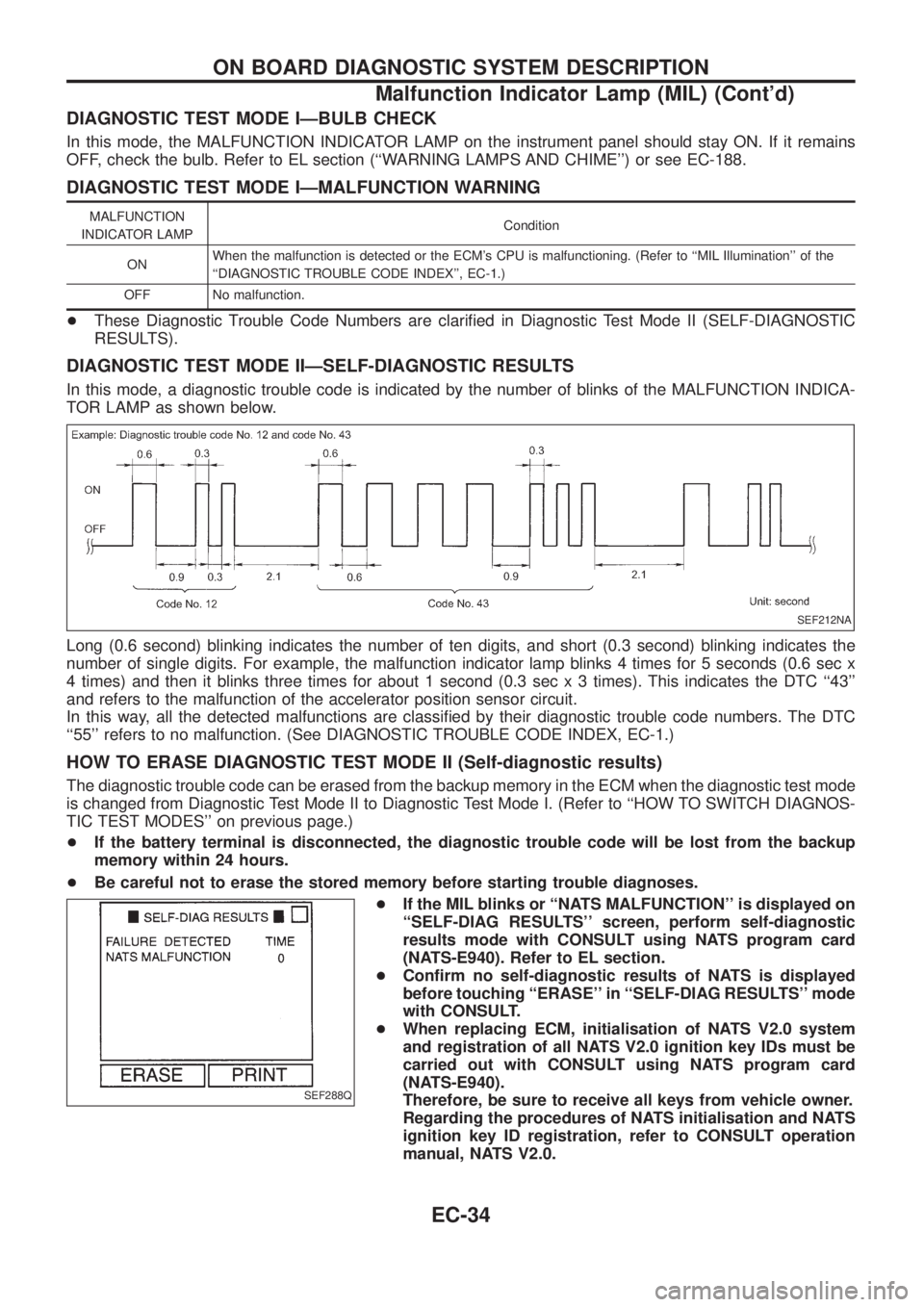
In this mode, a diagnostic trouble code is indicated by the number of blinks of the MALFUNCTION INDICA-
TOR LAMP as shown below.
Long (0.6 second) blinking indicates the number of ten digits, and short (0.3 second) blinking indicates the
number of single digits. For example, the malfunction indicator lamp blinks 4 times for 5 seconds (0.6 sec x
4 times) and then it blinks three times for about 1 second (0.3 sec x 3 times). This indicates the DTC ``43''
and refers to the malfunction of the accelerator position sensor circuit.
In this way, all the detected malfunctions are classi®ed by their diagnostic trouble code numbers. The DTC
``55'' refers to no malfunction. (See DIAGNOSTIC TROUBLE CODE INDEX, EC-1.)
HOW TO ERASE DIAGNOSTIC TEST MODE II (Self-diagnostic results)
The diagnostic trouble code can be erased from the backup memory in the ECM when the diagnostic test mode
is changed from Diagnostic Test Mode II to Diagnostic Test Mode I. (Refer to ``HOW TO SWITCH DIAGNOS-
TIC TEST MODES'' on previous page.)
+If the battery terminal is disconnected, the diagnostic trouble code will be lost from the backup
memory within 24 hours.
+Be careful not to erase the stored memory before starting trouble diagnoses.
+If the MIL blinks or ``NATS MALFUNCTION'' is displayed on
``SELF-DIAG RESULTS'' screen, perform self-diagnostic
results mode with CONSULT using NATS program card
(NATS-E940). Refer to EL section.
+Con®rm no self-diagnostic results of NATS is displayed
before touching ``ERASE'' in ``SELF-DIAG RESULTS'' mode
with CONSULT.
+When replacing ECM, initialisation of NATS V2.0 system
and registration of all NATS V2.0 ignition key IDs must be
carried out with CONSULT using NATS program card
(NATS-E940).
Therefore, be sure to receive all keys from vehicle owner.
Regarding the procedures of NATS initialisation and NATS
ignition key ID registration, refer to CONSULT operation
manual, NATS V2.0.
SEF212NA
SEF288Q
ON BOARD DIAGNOSTIC SYSTEM DESCRIPTION
Malfunction Indicator Lamp (MIL) (Cont'd)
EC-34
Page 266 of 1226
OVERALL FUNCTION CHECK
Use this procedure to check the overall function of the cooling fan.
During this check, a DTC might not be con®rmed.
WARNING:
Never remove the radiator cap when the engine is hot. Serious
burns could be caused by high pressure ¯uid escaping from
the radiator.
Wrap a thick cloth around the cap. Carefully remove the cap
by turning it a quarter turn to allow built-up pressure to
escape. Then turn the cap all the way off.
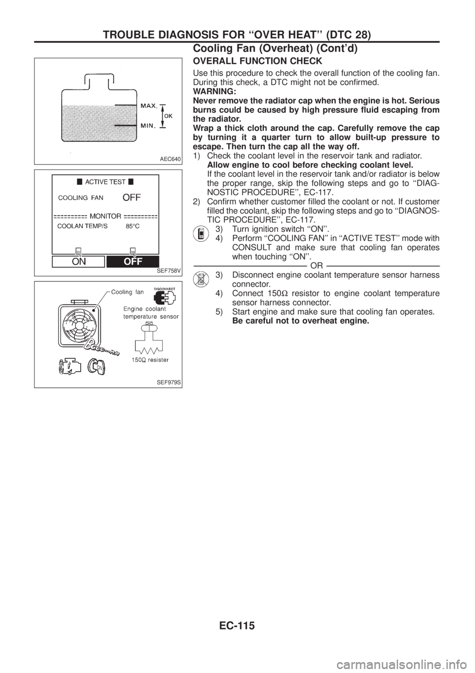
1) Check the coolant level in the reservoir tank and radiator.
Allow engine to cool before checking coolant level.
If the coolant level in the reservoir tank and/or radiator is below
the proper range, skip the following steps and go to ``DIAG-
NOSTIC PROCEDURE'', EC-117.
2) Con®rm whether customer ®lled the coolant or not. If customer
®lled the coolant, skip the following steps and go to ``DIAGNOS-
TIC PROCEDURE'', EC-117.
3) Turn ignition switch ``ON''.
4) Perform ``COOLING FAN'' in ``ACTIVE TEST'' mode with
CONSULT and make sure that cooling fan operates
when touching ``ON''.
-------------------------------------------------------------------------------------------------------------------------------------------------------------------------------------------------------------------------------------------------------OR-------------------------------------------------------------------------------------------------------------------------------------------------------------------------------------------------------------------------------------------------------
3) Disconnect engine coolant temperature sensor harness
connector.
4) Connect 150Wresistor to engine coolant temperature
sensor harness connector.
5) Start engine and make sure that cooling fan operates.
Be careful not to overheat engine.
AEC640
SEF758V
SEF979S
TROUBLE DIAGNOSIS FOR ``OVER HEAT'' (DTC 28)
Cooling Fan (Overheat) (Cont'd)
EC-115
Page 343 of 1226

Wiring Diagram Ð H/AIM Ð .....................................71
PARKING, LICENSE AND TAIL LAMPS......................73
Wiring Diagram Ð TAIL/L Ð/Type A .........................73
Wiring Diagram Ð TAIL/L Ð/Type B.........................75
STOP LAMP..................................................................77
Wiring Diagram Ð STOP/L Ð/Type A ......................77
BACK-UP LAMP............................................................78
Wiring Diagram Ð BACK/L Ð/LHD Models..............78
Wiring Diagram Ð BACK/L Ð/RHD Models .............79
REAR FOG LAMP.........................................................80
Wiring Diagram Ð R/FOG Ð ....................................80
TURN SIGNAL AND HAZARD WARNING LAMPS.....81
Wiring Diagram Ð TURN Ð/Type A .........................81
Wiring Diagram Ð TURN Ð/Type B .........................83
Trouble Diagnoses.....................................................85
Electrical Components Inspection .............................85
ILLUMINATION..............................................................86
Schematic ..................................................................86
Wiring Diagram Ð ILL Ð ..........................................87
INTERIOR ROOM LAMP Ð With Timer Ð.................93
System Description ....................................................93
Schematic ..................................................................94
Wiring Diagram Ð ROOM/L Ð/LHD Models ............95
Wiring Diagram Ð ROOM/L Ð/RHD Models............98
Trouble Diagnoses...................................................100
MAP AND VANITY MIRROR LAMPS.........................101
Wiring Diagram Ð INT/L Ð.....................................101
METER AND GAUGES...............................................102
System Description ..................................................102
Combination Meter ..................................................103
Wiring Diagram Ð METER Ð/LHD Models............104
Wiring Diagram Ð METER Ð/RHD Models ...........106
Meter/Gauge Operation and Odo/Trip Meter
Segment Check in Diagnosis Mode ........................108
Flexible Print Circuit (FPC) ......................................109
Trouble Diagnoses................................................... 110
Electrical Components Inspection ........................... 114
COMPASS AND THERMOMETER............................. 116
System Description .................................................. 116
Wiring Diagram Ð COMPAS Ð .............................. 117
Trouble Diagnoses................................................... 118
Calibration Procedure For Compass ....................... 119
WARNING LAMPS......................................................121
Schematic ................................................................121
Wiring Diagram Ð WARN Ð ..................................123
Electrical Components Inspection ...........................134
WARNING CHIME.......................................................135
System Description ..................................................135
Wiring Diagram Ð CHIME Ð/LHD Models.............136
Wiring Diagram Ð CHIME Ð/RHD Models ............137
Trouble Diagnoses...................................................138
Electrical Components Inspection ...........................140FRONT WIPER AND WASHER..................................141
System Description ..................................................141
Wiring Diagram Ð WIPER Ð/With Intermittent
Wiper........................................................................142
Removal and Installation .........................................143
Washer Nozzle Adjustment .....................................144
Washer Tube Layout ...............................................144
REAR WIPER AND WASHER....................................145
System Description ..................................................145
Wiring Diagram Ð WIP/R Ð/LHD Models ..............146
Wiring Diagram Ð WIP/R Ð/RHD Models .............148
Trouble Diagnoses...................................................150
Removal and Installation .........................................151
Washer Nozzle Adjustment .....................................151
Washer Tube Layout ...............................................152
Check Valve .............................................................152
HEADLAMP WIPER AND WASHER..........................153
Wiring Diagram Ð HLC Ð ......................................153
Electrical Components Inspection ...........................154
Removal and Installation .........................................154
Washer Tube Layout ...............................................154
Check Valve .............................................................154
HORN...........................................................................155
Wiring Diagram Ð HORN Ð...................................155
CIGARETTE LIGHTER................................................156
Wiring Diagram Ð CIGAR Ð ..................................156
CLOCK.........................................................................157
Wiring Diagram Ð CLOCK Ð .................................157
REAR WINDOW DEFOGGER.....................................158
System Description ..................................................158
Wiring Diagram Ð DEF Ð/LHD Models .................159
Wiring Diagram Ð DEF Ð/RHD Models ................161
Trouble Diagnoses...................................................163
Electrical Components Inspection ...........................164
Filament Check ........................................................164
Filament Repair .......................................................165
WIPER DEICER...........................................................166
System Description ..................................................166
Wiring Diagram Ð DEICER Ð................................167
AUDIO..........................................................................168
Wiring Diagram Ð AUDIO Ð/LHD Models .............168
Wiring Diagram Ð AUDIO Ð/RHD Models ............170
Trouble Diagnoses...................................................172
CATS (Code) System/RHD .....................................173
NATS Audio Link/LHD .............................................174
AUDIO Ð CD AUTO CHANGER Ð...........................176
Wiring Diagram Ð CD/CHG Ð/LHD Wagon ..........176
Wiring Diagram Ð CD/CHG Ð/LHD Hardtop .........177
Wiring Diagram Ð CD/CHG Ð/RHD Wagon ..........178
Wiring Diagram Ð CD/CHG Ð/RHD Hardtop ........179
Trouble Diagnoses...................................................180
AUDIO ANTENNA.......................................................181
Page 346 of 1226
Supplemental Restraint System (SRS) ``AIR
BAG'' and ``SEAT BELT PRE-TENSIONER''
The Supplemental Restraint System such as ``AIR BAG'' and ``SEAT BELT PRE-TENSIONER'' used along with
a seat belt, helps to reduce the risk or severity of injury to the driver and front passenger in a frontal collision.
The SRS system composition which is available to NISSAN MODEL Y61 is as follows (The composition var-
ies according to the destination.):
Driver air bag module (located in the center of the steering wheel), front passenger air bag module (located
on the instrument panel on passenger side), seat belt pre-tensioner, a diagnosis sensor unit, warning lamp,
wiring harness and spiral cable.
Information necessary to service the system safely is included in theRS sectionof this Service Manual.
WARNING:
+To avoid rendering the SRS inoperative, which could increase the risk of personal injury or death
in the event of a collision which would result in air bag in¯ation, all maintenance must be performed
by an authorized NISSAN dealer.
+Improper maintenance, including incorrect removal and installation of the SRS, can lead to per-
sonal injury caused by unintentional activation of the system. For removal of Spiral Cable and Air
Bag Module, see the RS section.
+Do not use electrical test equipment on any circuit related to the SRS unless instructed to in this
Service Manual. Spiral cable and wiring harnesses covered with yellow insulation either just before
the harness connectors or for the complete harness are related to the SRS.
PRECAUTIONS
EL-1
Page 382 of 1226
CAUTION:
If it becomes necessary to start the engine with a booster bat-
tery and jumper cables,
a. Use a 12-volt booster battery.
b. After connecting battery cables, ensure that they are
tightly clamped to battery terminals for good contact.
c. Never add distilled water through the hole used to check
speci®c gravity.
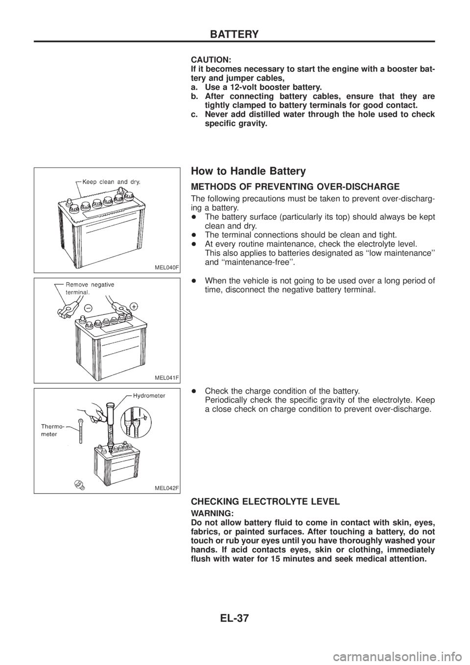
How to Handle Battery
METHODS OF PREVENTING OVER-DISCHARGE
The following precautions must be taken to prevent over-discharg-
ing a battery.
+The battery surface (particularly its top) should always be kept
clean and dry.
+The terminal connections should be clean and tight.
+At every routine maintenance, check the electrolyte level.
This also applies to batteries designated as ``low maintenance''
and ``maintenance-free''.
+When the vehicle is not going to be used over a long period of
time, disconnect the negative battery terminal.
+Check the charge condition of the battery.
Periodically check the speci®c gravity of the electrolyte. Keep
a close check on charge condition to prevent over-discharge.
CHECKING ELECTROLYTE LEVEL
WARNING:
Do not allow battery ¯uid to come in contact with skin, eyes,
fabrics, or painted surfaces. After touching a battery, do not
touch or rub your eyes until you have thoroughly washed your
hands. If acid contacts eyes, skin or clothing, immediately
¯ush with water for 15 minutes and seek medical attention.
MEL040F
MEL041F
MEL042F
BATTERY
EL-37
Page 398 of 1226
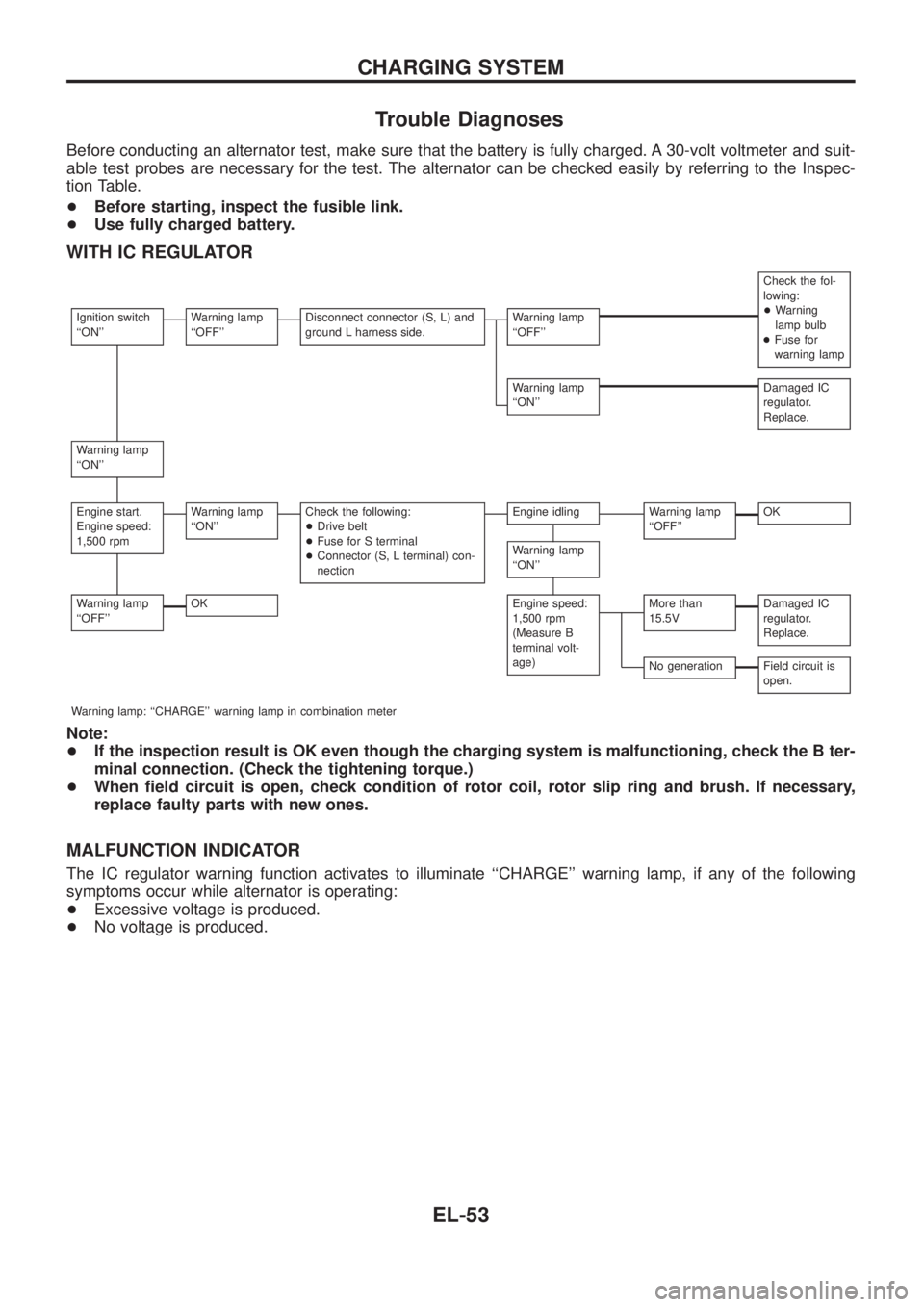
Trouble Diagnoses
Before conducting an alternator test, make sure that the battery is fully charged. A 30-volt voltmeter and suit-
able test probes are necessary for the test. The alternator can be checked easily by referring to the Inspec-
tion Table.
+Before starting, inspect the fusible link.
+Use fully charged battery.
WITH IC REGULATOR
Check the fol-
lowing:
+Warning
lamp bulb
+Fuse for
warning lamp
Ignition switch
``ON''Warning lamp
``OFF''Disconnect connector (S, L) and
ground L harness side.Warning lamp
``OFF''
Warning lamp
``ON''Damaged IC
regulator.
Replace.
Warning lamp
``ON''
Engine start.
Engine speed:
1,500 rpmWarning lamp
``ON''Check the following:
+Drive belt
+Fuse for S terminal
+Connector (S, L terminal) con-
nectionEngine idlingWarning lamp
``OFF''OK
Warning lamp
``ON''
Warning lamp
``OFF''OKEngine speed:
1,500 rpm
(Measure B
terminal volt-
age)More than
15.5VDamaged IC
regulator.
Replace.
No generationField circuit is
open.
Warning lamp: ``CHARGE'' warning lamp in combination meter
Note:
+If the inspection result is OK even though the charging system is malfunctioning, check the B ter-
minal connection. (Check the tightening torque.)
+When ®eld circuit is open, check condition of rotor coil, rotor slip ring and brush. If necessary,
replace faulty parts with new ones.
MALFUNCTION INDICATOR
The IC regulator warning function activates to illuminate ``CHARGE'' warning lamp, if any of the following
symptoms occur while alternator is operating:
+Excessive voltage is produced.
+No voltage is produced.
CHARGING SYSTEM
EL-53
Page 426 of 1226
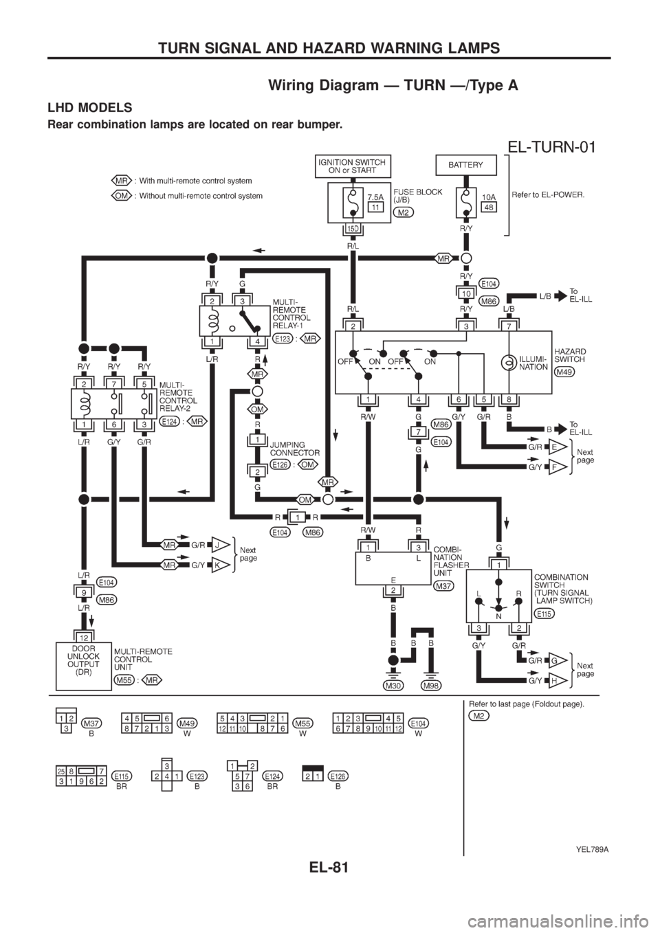
Wiring Diagram Ð TURN Ð/Type A
LHD MODELS
Rear combination lamps are located on rear bumper.
YEL789A
TURN SIGNAL AND HAZARD WARNING LAMPS
EL-81