2006 NISSAN PATROL warning
[x] Cancel search: warningPage 991 of 1226
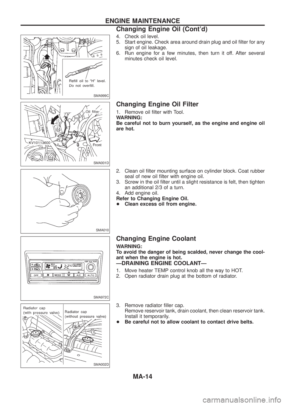
4. Check oil level.
5. Start engine. Check area around drain plug and oil ®lter for any
sign of oil leakage.
6. Run engine for a few minutes, then turn it off. After several
minutes check oil level.
Changing Engine Oil Filter
1. Remove oil ®lter with Tool.
WARNING:
Be careful not to burn yourself, as the engine and engine oil
are hot.
2. Clean oil ®lter mounting surface on cylinder block. Coat rubber
seal of new oil ®lter with engine oil.
3. Screw in the oil ®lter until a slight resistance is felt, then tighten
an additional 2/3 of a turn.
4. Add engine oil.
Refer to Changing Engine Oil.
+Clean excess oil from engine.
Changing Engine Coolant
WARNING:
To avoid the danger of being scalded, never change the cool-
ant when the engine is hot.
ÐDRAINING ENGINE COOLANTÐ
1. Move heater TEMP control knob all the way to HOT.
2. Open radiator drain plug at the bottom of radiator.
3. Remove radiator ®ller cap.
Remove reservoir tank, drain coolant, then clean reservoir tank.
Install it temporarily.
+Be careful not to allow coolant to contact drive belts.
SMA999C
SMA001D
SMA010
SMA972C
SMA002D
ENGINE MAINTENANCE
Changing Engine Oil (Cont'd)
MA-14
Page 995 of 1226
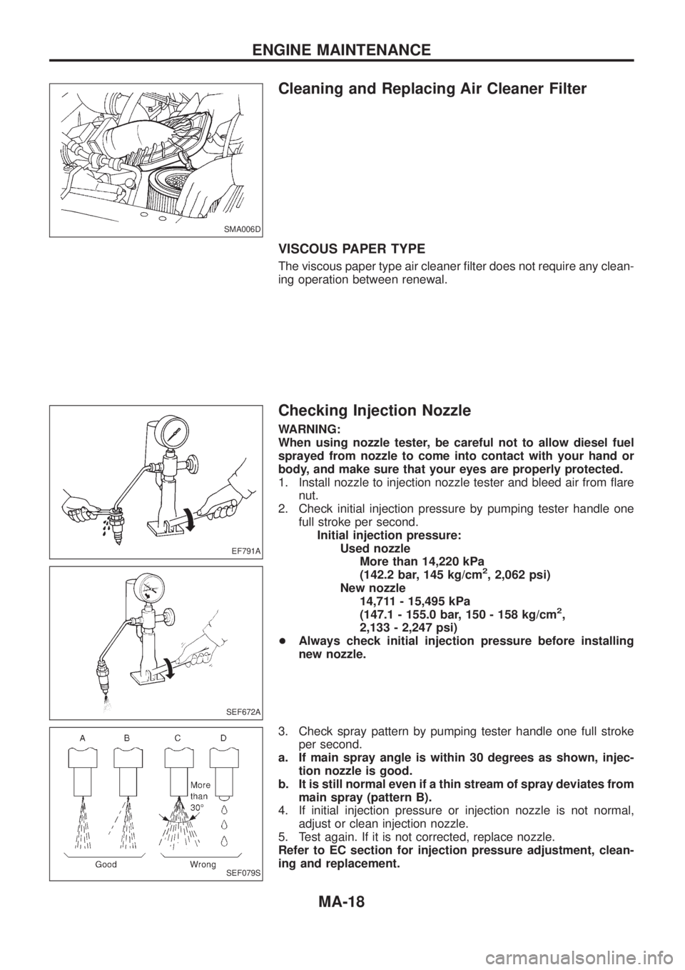
Cleaning and Replacing Air Cleaner Filter
VISCOUS PAPER TYPE
The viscous paper type air cleaner ®lter does not require any clean-
ing operation between renewal.
Checking Injection Nozzle
WARNING:
When using nozzle tester, be careful not to allow diesel fuel
sprayed from nozzle to come into contact with your hand or
body, and make sure that your eyes are properly protected.
1. Install nozzle to injection nozzle tester and bleed air from ¯are
nut.
2. Check initial injection pressure by pumping tester handle one
full stroke per second.
Initial injection pressure:
Used nozzle
More than 14,220 kPa
(142.2 bar, 145 kg/cm
2, 2,062 psi)
New nozzle
14,711 - 15,495 kPa
(147.1 - 155.0 bar, 150 - 158 kg/cm
2,
2,133 - 2,247 psi)
+Always check initial injection pressure before installing
new nozzle.
3. Check spray pattern by pumping tester handle one full stroke
per second.
a. If main spray angle is within 30 degrees as shown, injec-
tion nozzle is good.
b. It is still normal even if a thin stream of spray deviates from
main spray (pattern B).
4. If initial injection pressure or injection nozzle is not normal,
adjust or clean injection nozzle.
5. Test again. If it is not corrected, replace nozzle.
Refer to EC section for injection pressure adjustment, clean-
ing and replacement.
SMA006D
EF791A
SEF672A
SEF079S
ENGINE MAINTENANCE
MA-18
Page 1012 of 1226
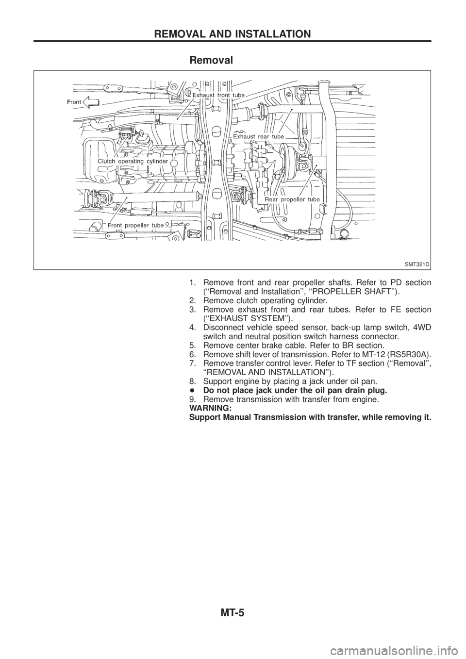
Removal
1. Remove front and rear propeller shafts. Refer to PD section
(``Removal and Installation'', ``PROPELLER SHAFT'').
2. Remove clutch operating cylinder.
3. Remove exhaust front and rear tubes. Refer to FE section
(``EXHAUST SYSTEM'').
4. Disconnect vehicle speed sensor, back-up lamp switch, 4WD
switch and neutral position switch harness connector.
5. Remove center brake cable. Refer to BR section.
6. Remove shift lever of transmission. Refer to MT-12 (RS5R30A).
7. Remove transfer control lever. Refer to TF section (``Removal'',
``REMOVAL AND INSTALLATION'').
8. Support engine by placing a jack under oil pan.
+Do not place jack under the oil pan drain plug.
9. Remove transmission with transfer from engine.
WARNING:
Support Manual Transmission with transfer, while removing it.
SMT321D
REMOVAL AND INSTALLATION
MT-5
Page 1085 of 1226
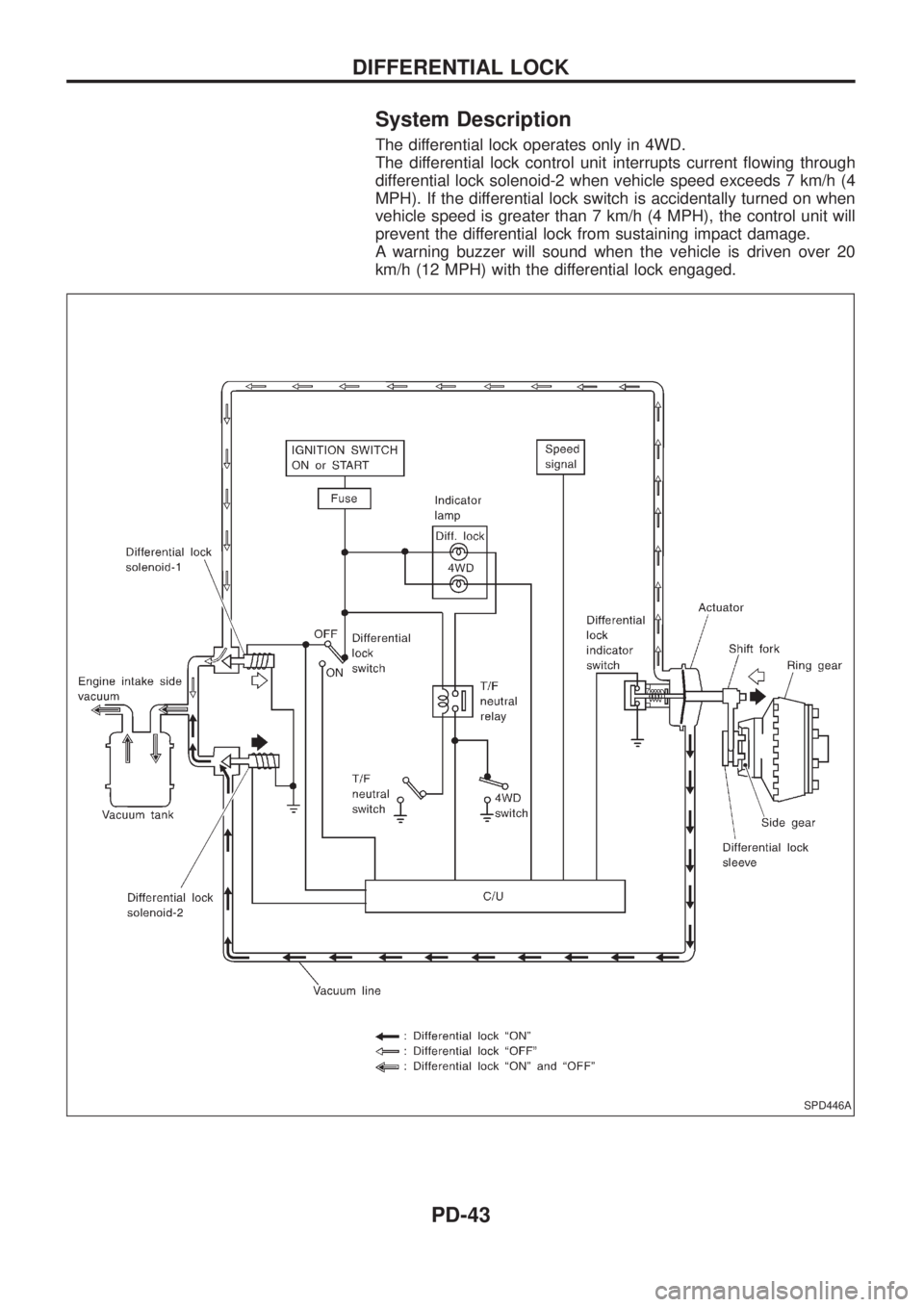
System Description
The differential lock operates only in 4WD.
The differential lock control unit interrupts current ¯owing through
differential lock solenoid-2 when vehicle speed exceeds 7 km/h (4
MPH). If the differential lock switch is accidentally turned on when
vehicle speed is greater than 7 km/h (4 MPH), the control unit will
prevent the differential lock from sustaining impact damage.
A warning buzzer will sound when the vehicle is driven over 20
km/h (12 MPH) with the differential lock engaged.
SPD446A
DIFFERENTIAL LOCK
PD-43
Page 1122 of 1226
RESTRAINT SYSTEM
SECTION
RS
CONTENTS
PRECAUTION..................................................................1
Supplemental Restraint System (SRS) ``AIR
BAG'' and ``SEAT BELT PRE-TENSIONER''...............1
SEAT BELTS...................................................................2
Front Seat Belt.............................................................3
Rear Seat Belt .............................................................5
3rd Seat Belt ................................................................7
SUPPLEMENTAL RESTRAINT SYSTEM (SRS)............8
Precautions for SRS ``AIR BAG'' and ``Seat Belt
Pre-tensioner'' Service.................................................8
Special Service Tools ..................................................8
Description .................................................................10
SRS Component Parts Location ...............................10
Maintenance Items .................................................... 11
Removal and Installation Ð Diagnosis Sensor
Unit and Seat Belt Pre-tensioner...............................12
Removal and Installation Ð Air Bag Module and
Spiral Cable ...............................................................13
Removal Ð Air Bag Module and Spiral Cable ..........13
Removal Ð Front Passenger Air Bag Module ..........14
Installation Ð Air Bag Module and Spiral Cable .......16Installation Ð Front Passenger Air Bag Module .......16
Disposal of Air Bag Module and Seat Belt Pre-
tensioner ....................................................................17
TROUBLE DIAGNOSES Ð Supplemental
Restraint System (SRS)...............................................22
Trouble Diagnoses Introduction.................................22
How to Perform Trouble Diagnoses for Quick
and Accurate Repair ..................................................24
Schematic ..................................................................26
Wiring Diagram Ð SRS Ð ........................................27
SRS Operation Check ...............................................30
Trouble Diagnoses with CONSULT ...........................32
Trouble Diagnoses without CONSULT ......................39
Trouble Diagnoses: ``AIR BAG'' Warning Lamp
Does Not Turn Off .....................................................43
Trouble Diagnoses: ``AIR BAG'' Warning Lamp
Does Not Turn On .....................................................43
Trouble Diagnoses: SRS Does Not Enter
Diagnosis Mode Using Door Switch ..........................44
COLLISION DIAGNOSIS...............................................45
When you read wiring diagrams:
+Read GI section, ``HOW TO READ WIRING DIAGRAMS''.
+See EL section, ``POWER SUPPLY ROUTING'' for power distribution circuit.
When you perform trouble diagnoses, read GI section, ``HOW TO FOLLOW FLOW
CHART IN TROUBLE DIAGNOSES'' and ``HOW TO PERFORM EFFICIENT DIAGNOSIS
FOR AN ELECTRICAL INCIDENT''.
RS
Page 1123 of 1226
Supplemental Restraint System (SRS) ``AIR
BAG'' and ``SEAT BELT PRE-TENSIONER''
The Supplemental Restraint System such as ``AIR BAG'' and ``SEAT BELT PRE-TENSIONER'' used along with
a seat belt, helps to reduce the risk or severity of injury to the driver and front passenger in a frontal collision.
The SRS composition which is available to NISSAN MODEL Y61 is as follows (The composition varies
according to the destination.):
Driver air bag module (located in the center of the steering wheel), front passenger air bag module (located
on the instrument panel on passenger side), seat belt pre-tensioner, a diagnosis sensor unit, warning lamp,
wiring harness and spiral cable.
WARNING:
+To avoid rendering the SRS inoperative, which could increase the risk of personal injury or death
in the event of a collision which would result in air bag in¯ation, all maintenance must be performed
by an authorized NISSAN dealer.
+Improper maintenance, including incorrect removal and installation of the SRS, can lead to per-
sonal injury caused by unintentional activation of the system.
+Do not use electrical test equipment on any circuit related to the SRS unless instructed to in this
Service Manual. Spiral cable and wiring harnesses covered with yellow insulation either just before
the harness connectors or for the complete harness are related to the SRS.
PRECAUTION
RS-1
Page 1133 of 1226
Maintenance Items
CAUTION:
Do not use a circuit tester to check SRS circuit.
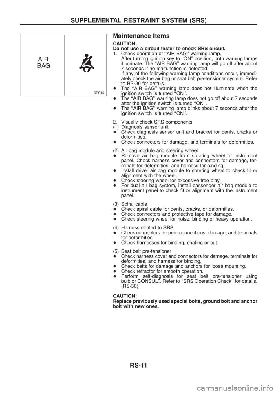
1. Check operation of ``AIR BAG'' warning lamp.
After turning ignition key to ``ON'' position, both warning lamps
illuminate. The ``AIR BAG'' warning lamp will go off after about
7 seconds if no malfunction is detected.
If any of the following warning lamp conditions occur, immedi-
ately check the air bag or seat belt pre-tensioner system. Refer
to RS-30 for details.
+The ``AIR BAG'' warning lamp does not illuminate when the
ignition switch is turned ``ON''.
+The ``AIR BAG'' warning lamp does not go off about 7 seconds
after the ignition switch is turned ``ON''.
+The ``AIR BAG'' warning lamp blinks about 7 seconds after the
ignition switch is turned ``ON''.
2. Visually check SRS components.
(1) Diagnosis sensor unit
+Check diagnosis sensor unit and bracket for dents, cracks or
deformities.
+Check connectors for damage, and terminals for deformities.
(2) Air bag module and steering wheel
+Remove air bag module from steering wheel or instrument
panel. Check harness cover and connectors for damage, ter-
minals for deformities, and harness for binding.
+Install driver air bag module to steering wheel to check ®t or
alignment with the wheel.
+Check steering wheel for excessive free play.
+For dual air bag system, install passenger air bag module to
instrument panel to check ®t or alignment with the instrument
panel.
(3) Spiral cable
+Check spiral cable for dents, cracks, or deformities.
+Check connectors and protective tape for damage.
+Check steering wheel for noise, binding or heavy operation.
(4) Harness related to SRS
+Check connectors for poor connections, damage, and terminals
for deformities.
+Check harnesses for binding, cha®ng or cut.
(5) Seat belt pre-tensioner
+Check harness cover and connectors for damage, terminals for
deformities, and harness for binding.
+Check belts for damage and anchors for loose mounting.
+Check retractor for smooth operation.
+Perform self-diagnosis for seat belt pre-tensioner using
bulb or CONSULT. Refer to ``SRS Operation Check'' for details.
(RS-30)
CAUTION:
Replace previously used special bolts, ground bolt and anchor
bolt with new ones.
SRS451
SUPPLEMENTAL RESTRAINT SYSTEM (SRS)
RS-11
Page 1138 of 1226
Installation Ð Air Bag Module and Spiral Cable
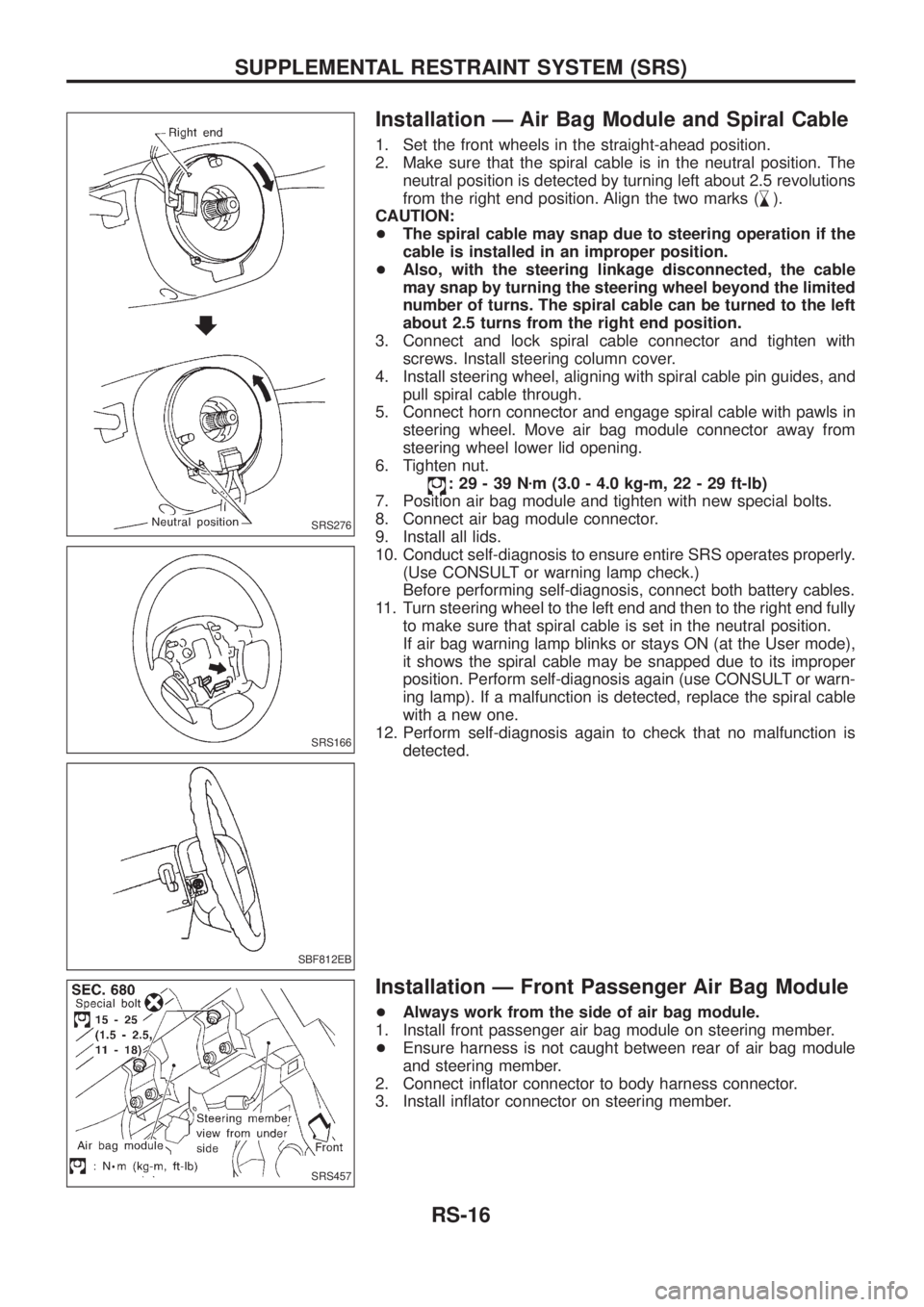
1. Set the front wheels in the straight-ahead position.
2. Make sure that the spiral cable is in the neutral position. The
neutral position is detected by turning left about 2.5 revolutions
from the right end position. Align the two marks (
,
m).
CAUTION:
+The spiral cable may snap due to steering operation if the
cable is installed in an improper position.
+Also, with the steering linkage disconnected, the cable
may snap by turning the steering wheel beyond the limited
number of turns. The spiral cable can be turned to the left
about 2.5 turns from the right end position.
3. Connect and lock spiral cable connector and tighten with
screws. Install steering column cover.
4. Install steering wheel, aligning with spiral cable pin guides, and
pull spiral cable through.
5. Connect horn connector and engage spiral cable with pawls in
steering wheel. Move air bag module connector away from
steering wheel lower lid opening.
6. Tighten nut.
:29-39Nzm (3.0 - 4.0 kg-m, 22 - 29 ft-lb)
7. Position air bag module and tighten with new special bolts.
8. Connect air bag module connector.
9. Install all lids.
10. Conduct self-diagnosis to ensure entire SRS operates properly.
(Use CONSULT or warning lamp check.)
Before performing self-diagnosis, connect both battery cables.
11. Turn steering wheel to the left end and then to the right end fully
to make sure that spiral cable is set in the neutral position.
If air bag warning lamp blinks or stays ON (at the User mode),
it shows the spiral cable may be snapped due to its improper
position. Perform self-diagnosis again (use CONSULT or warn-
ing lamp). If a malfunction is detected, replace the spiral cable
with a new one.
12. Perform self-diagnosis again to check that no malfunction is
detected.
Installation Ð Front Passenger Air Bag Module
+Always work from the side of air bag module.
1. Install front passenger air bag module on steering member.
+Ensure harness is not caught between rear of air bag module
and steering member.
2. Connect in¯ator connector to body harness connector.
3. Install in¯ator connector on steering member.
SRS276
SRS166
SBF812EB
SRS457
SUPPLEMENTAL RESTRAINT SYSTEM (SRS)
RS-16