2006 NISSAN PATROL warning
[x] Cancel search: warningPage 776 of 1226
+Clean all disassembled parts in the designated liquid or solvent
prior to inspection or assembly.
+Replace oil seals, gaskets, packings, O-rings, locking washers,
cotter pins, self-locking nuts, etc. with new ones.
+Replace inner and outer races of tapered roller bearings and
needle bearings as a set.
+Arrange the disassembled parts in accordance with their
assembled locations and sequence.
+Do not touch the terminals of electrical components which use
microcomputers (such as ECMs).
Static electricity may damage internal electronic components.
+After disconnecting vacuum or air hoses, attach a tag to indi-
cate the proper connection.
+Use only the ¯uids and lubricants speci®ed in this manual.
+Use approved bonding agent, sealants or their equivalents
when required.
+Use tools and recommended special tools where speci®ed for
safe and efficient service repairs.
+When repairing the fuel, oil, water, vacuum or exhaust systems,
check all affected lines for leaks.
+Dispose of drained oil or the solvent used for cleaning parts in
an appropriate manner.
WARNING:
To prevent ECM from storing the diagnostic trouble codes, do
not carelessly disconnect the harness connectors which are
related to the ECCS system and TCM (Transmission Control
Module) system. The connectors should be disconnected only
when working according to the WORK FLOW of TROUBLE
DIAGNOSES in EC and AT sections.
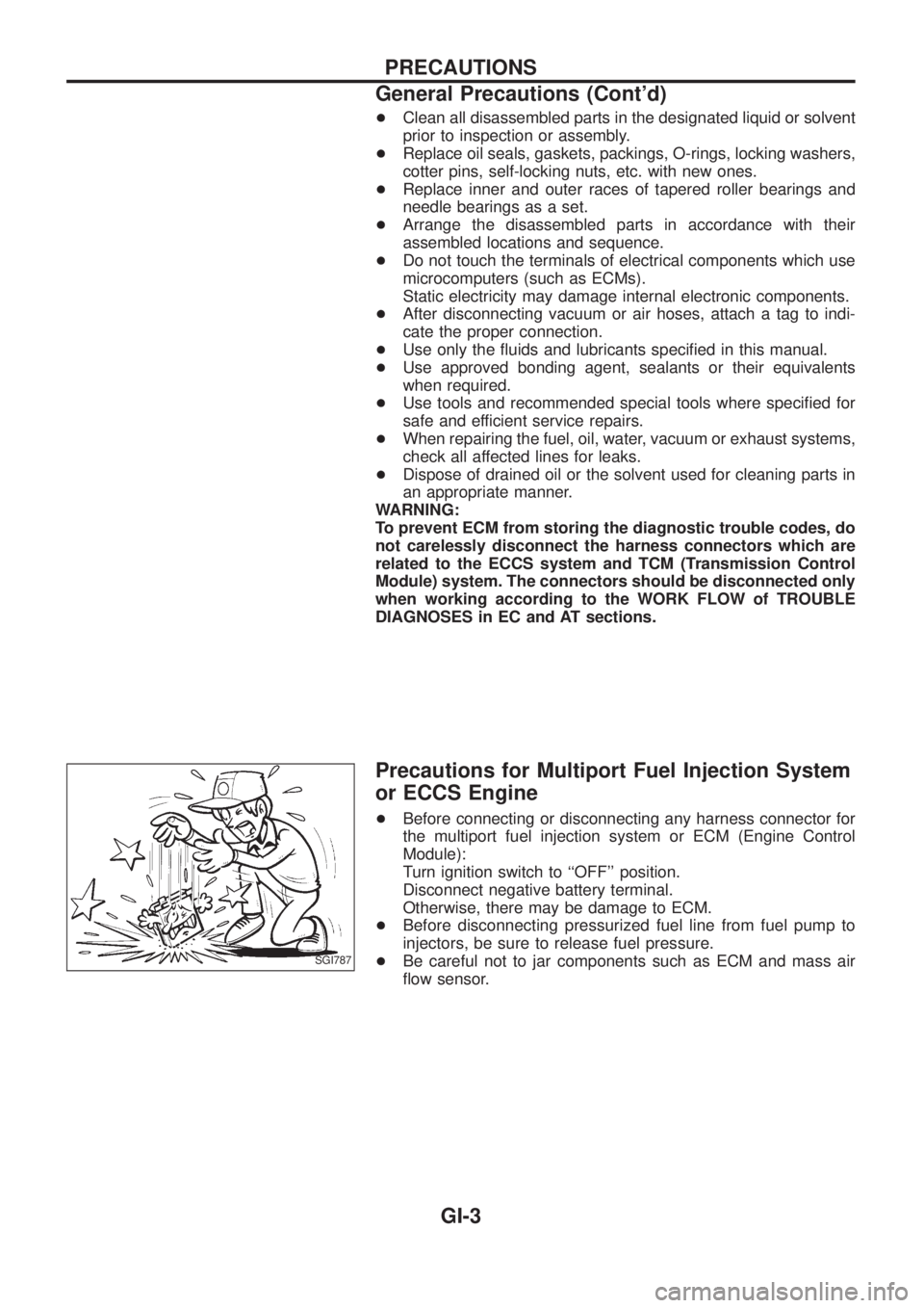
Precautions for Multiport Fuel Injection System
or ECCS Engine
+Before connecting or disconnecting any harness connector for
the multiport fuel injection system or ECM (Engine Control
Module):
Turn ignition switch to ``OFF'' position.
Disconnect negative battery terminal.
Otherwise, there may be damage to ECM.
+
Before disconnecting pressurized fuel line from fuel pump to
injectors, be sure to release fuel pressure.
+Be careful not to jar components such as ECM and mass air
¯ow sensor.SGI787
PRECAUTIONS
General Precautions (Cont'd)
GI-3
Page 780 of 1226
+The followingSYMBOLS AND ABBREVIATIONSare used:
,: Tightening torque
: Should be lubricated with grease.
Unless otherwise indicated, use rec-
ommended multi-purpose grease.
: Should be lubricated with oil.
: Sealing point
: Checking point
: Always replace after every disas-
sembly.
jP: Apply petroleum jelly.
: Apply ATF.
.: Select with proper thickness.
>: Adjustment is required.
SDS : Service Data and Speci®cations
LH, RH : Left-Hand, Right-Hand
FR, RR : Front, Rear
M/T : Manual Transaxle/Transmission
,
4WD : 4-Wheel Drive
2WD : 2-Wheel Drive
A/C : Air Conditioner
P/S : Power Steering
SST : Special Service Tools
SAE : Society of Automotive Engineers,
Inc.
ATF : Automatic Transmission Fluid
D
1: Drive range 1st gear
D
2: Drive range 2nd gear
D
3: Drive range 3rd gear
D
4: Drive range 4th gear
OD : Overdrive
2
2: 2nd range 2nd gear
2
1: 2nd range 1st gear
1
2: 1st range 2nd gear
1
1: 1st range 1st gear
+TheUNITSgiven in this manual are primarily expressed as the SI UNIT (International System of Unit),
and alternatively expressed in the metric system and in the yard/pound system.
``Example''
Tightening torque:
59-78Nzm (6.0 - 8.0 kg-m, 43 - 58 ft-lb)
+TROUBLE DIAGNOSESare included in sections dealing with complicated components.
+SERVICE DATA AND SPECIFICATIONSare contained at the end of each section for quick reference of
data.
+The captionsWARNINGandCAUTIONwarn you of steps that must be followed to prevent personal injury
and/or damage to some part of the vehicle.
WARNINGindicates the possibility of personal injury if instructions are not followed.
CAUTIONindicates the possibility of component damage if instructions are not followed.
BOLD TYPED STATEMENTSexceptWARNINGandCAUTIONgive you helpful information.
HOW TO USE THIS MANUAL
GI-7
Page 806 of 1226
Function and System Application
Diagnostic
test modeFunction ECCS Air bag ABS*
Work supportThis mode enables a technician to adjust
some devices faster and more accurately by
following the indications on CONSULT.xÐÐ
Self-diagnostic
resultsSelf-diagnostic results can be read and
erased quickly.xxx
Trouble diagnostic
recordCurrent self-diagnostic results and all trouble
diagnostic records previously stored can be
read.ÐxÐ
ECU discriminated
No.Classi®cation number of a replacement ECU
can be read to prevent an incorrect ECU
from being installed.ÐxÐ
Data monitor Input/Output data in the ECM can be read. x Ð x
Active testDiagnostic Test Mode in which CONSULT
drives some actuators apart from the ECMs
and also shifts some parameters in a speci-
®ed range.xÐx
ECM part number ECM part number can be read. x Ð x
Function testConducted by CONSULT instead of a tech-
nician to determine whether each system is
``OK'' or ``NG''.xÐÐ
x: Applicable
*: EE960 program card is not applicable to ABS. Use on board diagnostic system with ABS warning lamp until the next program card
will be introduced.
Lithium Battery Replacement
CONSULT contains a lithium battery. When replacing the battery obey the following:
WARNING:
Replace the lithium battery with SANYO Electric Co., Ltd., CR2032 only. Use of another battery may
present a risk of ®re or explosion. The battery may present a ®re or chemical burn hazard if mistreated.
Do not recharge, disassemble of dispose of in ®re.
Keep the battery out of reach of children and discard used battery conforming to the local regulations.
Checking Equipment
When ordering the below equipment, contact your NISSAN distributor.
Tool name Description
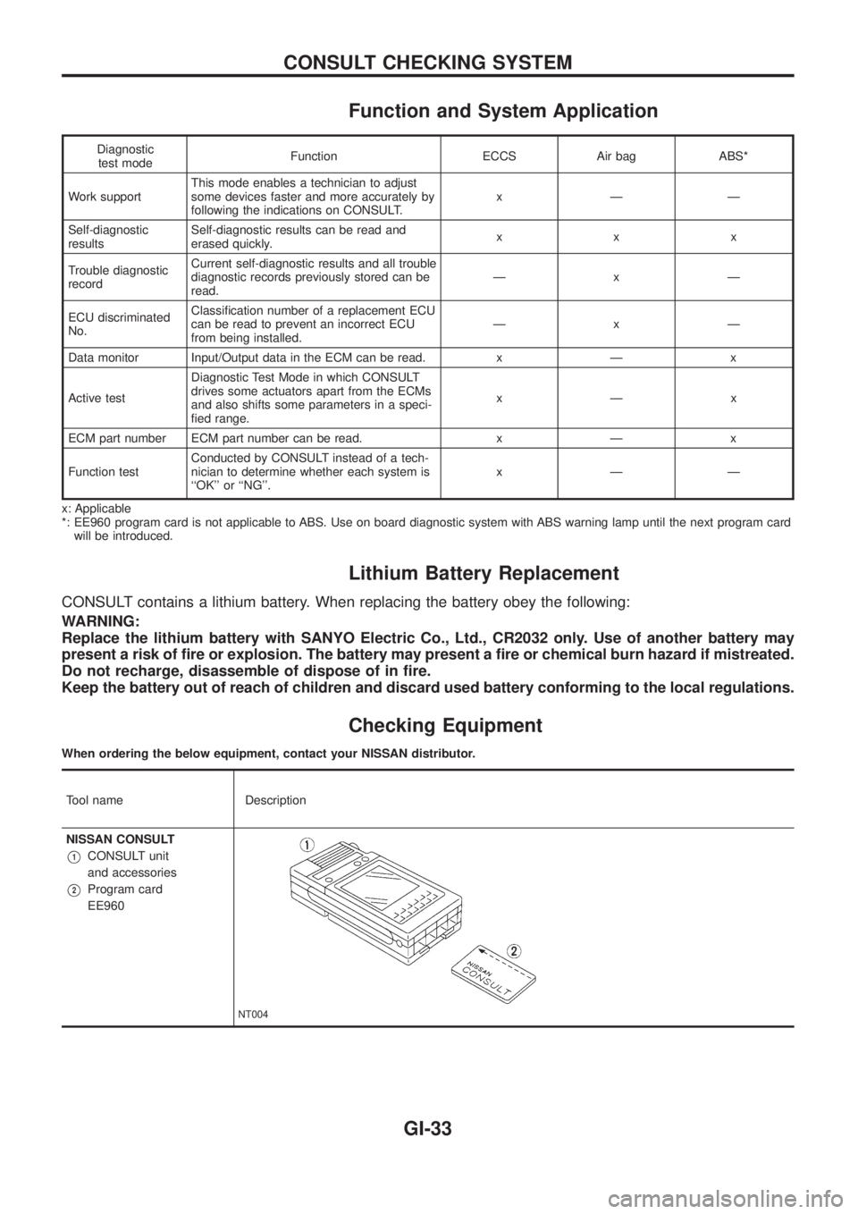
NISSAN CONSULT
V1CONSULT unit
and accessories
V2Program card
EE960
NT004
CONSULT CHECKING SYSTEM
GI-33
Page 812 of 1226
WARNING:
+Never get under the vehicle while it is supported only by the jack. Always use safety stands to
support the frame when you have to get under the vehicle.
+Place wheel chocks at both front and back of the wheel which is diagonally opposite the jack
position.
Example: If the jack is positioned at the LH front wheel, place wheel chocks at RH rear wheel.
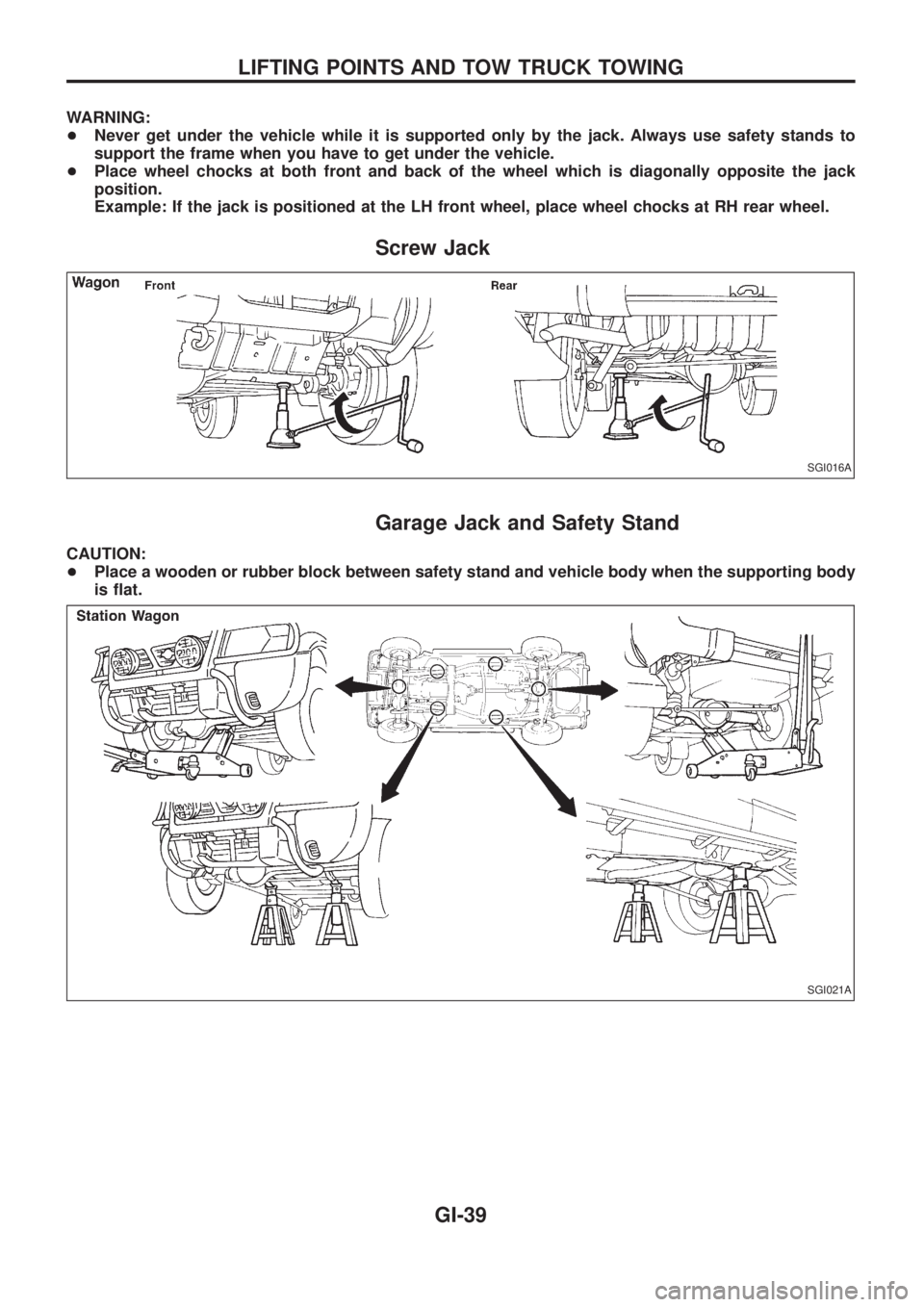
Screw Jack
Garage Jack and Safety Stand
CAUTION:
+Place a wooden or rubber block between safety stand and vehicle body when the supporting body
is ¯at.
SGI016A
SGI021A
LIFTING POINTS AND TOW TRUCK TOWING
GI-39
Page 813 of 1226
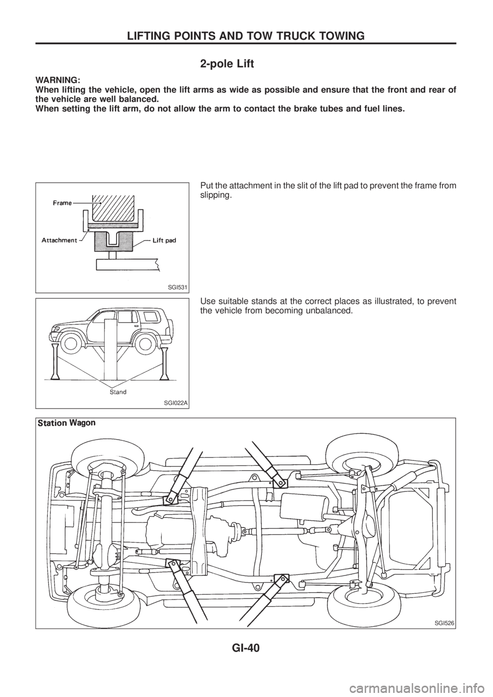
2-pole Lift
WARNING:
When lifting the vehicle, open the lift arms as wide as possible and ensure that the front and rear of
the vehicle are well balanced.
When setting the lift arm, do not allow the arm to contact the brake tubes and fuel lines.
Put the attachment in the slit of the lift pad to prevent the frame from
slipping.
Use suitable stands at the correct places as illustrated, to prevent
the vehicle from becoming unbalanced.
SGI531
SGI022A
SGI526
LIFTING POINTS AND TOW TRUCK TOWING
GI-40
Page 822 of 1226
Supplemental Restraint System (SRS) ``AIR
BAG'' and ``SEAT BELT PRE-TENSIONER''
The Supplemental Restraint System such as ``AIR BAG'' and ``SEAT BELT PRE-TENSIONER'' used along with
a seat belt, helps to reduce the risk or severity of injury to the driver and front passenger in a frontal collision.
The SRS system composition which is available to NISSAN MODEL Y61 is as follows (The composition var-
ies according to the destination.):
Driver air bag module (located in the center of the steering wheel), front passenger air bag module (located
on the instrument panel on passenger side), seat belt pre-tensioner, a diagnosis sensor unit, warning lamp,
wiring harness and spiral cable.
Information necessary to service the system safely is included in theRS sectionof this Service Manual.
WARNING:
+To avoid rendering the SRS inoperative, which could increase the risk of personal injury or death
in the event of a collision which would result in air bag in¯ation, all maintenance must be performed
by an authorized NISSAN dealer.
+Improper maintenance, including incorrect removal and installation of the SRS, can lead to per-
sonal injury caused by unintentional activation of the system. For removal of Spiral Cable and Air
Bag Module, see the RS section.
+Do not use electrical test equipment on any circuit related to the SRS unless instructed to in this
Service Manual. Spiral cable and wiring harnesses covered with yellow insulation either just before
the harness connectors or for the complete harness are related to the SRS.
Precautions for Working with HFC-134a
(R-134a)
WARNING:
+CFC-12 (R-12) refrigerant and HFC-134a (R-134a) refrigerant are not compatible. These refriger-
ants must never be mixed, even in the smallest amounts. If the refrigerants are mixed, compres-
sor failure is likely to occur.
+Use only speci®ed lubricant for the HFC-134a (R-134a) A/C system and HFC-134a (R-134a) com-
ponents. If lubricant other than that speci®ed is used, compressor failure is likely to occur.
+The speci®ed HFC-134a (R-134a) lubricant rapidly absorbs moisture from the atmosphere. The
following handling precautions must be observed:
a: When removing refrigerant components from a vehicle, immediately cap (seal) the component
to minimize the entry of moisture from the atmosphere.
b: When installing refrigerant components to a vehicle, do not remove the caps (unseal) until
just before connecting the components. Connect all refrigerant loop components as quickly
as possible to minimize the entry of moisture into system.
c: Only use the speci®ed lubricant from a sealed container. Immediately reseal containers of
lubricant. Without proper sealing, lubricant will become moisture saturated and should not
be used.
d: Avoid breathing A/C refrigerant and lubricant vapor or mist. Exposure may irritate eyes, nose
and throat. Use only approved recovery/recycling equipment to discharge HFC-134a (R-134a)
refrigerant. If accidental system discharge occurs, ventilate work area before resuming ser-
vice. Additional health and safety information may be obtained from refrigerant and lubricant
manufacturers.
e: Do not allow lubricant (Nissan A/C System Oil Type S) to come in contact with styrofoam
parts. Damage may result.
PRECAUTIONS AND PREPARATIONMANUAL AND AUTO
HA-1
Page 823 of 1226
General Refrigerant Precautions
WARNING:
+Do not release refrigerant into the air. Use approved recovery/recycling equipment to capture the
refrigerant every time an air conditioning system is discharged.
+Always wear eye and hand protection (goggles and gloves) when working with any refrigerant or
air conditioning system.
+Do not store or heat refrigerant containers above 52ÉC.
+Do not heat a refrigerant container with an open ¯ame; if container warming is required, place the
bottom of the container in a warm pail of water.
+Do not intentionally drop, puncture, or incinerate refrigerant containers.
+Keep refrigerant away from open ¯ames: poisonous gas will be produced if refrigerant burns.
+Refrigerant will displace oxygen, therefore be certain to work in well ventilated areas to prevent
suffocation.
+Do not introduce compressed air to any refrigerant container or refrigerant component.
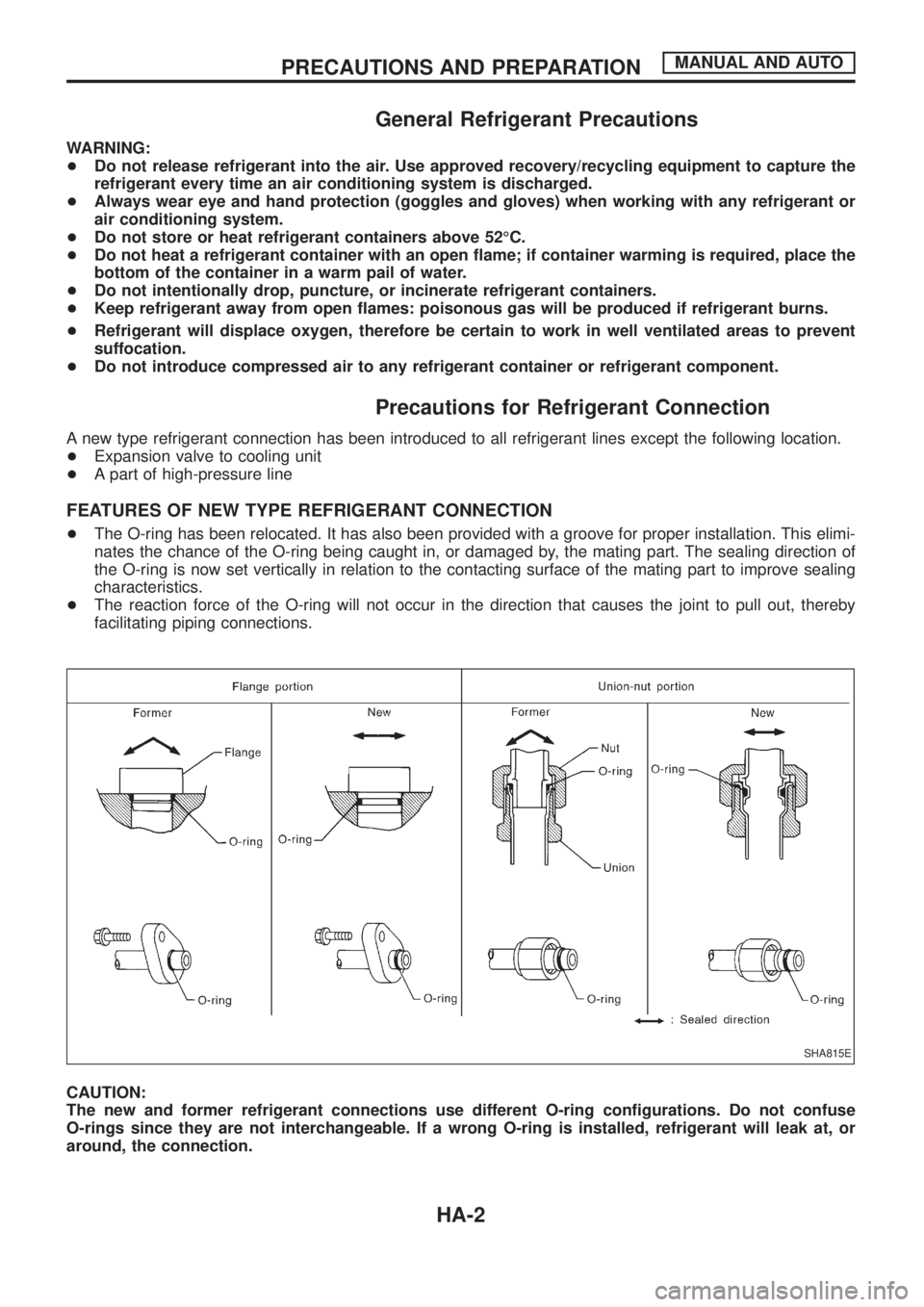
Precautions for Refrigerant Connection
A new type refrigerant connection has been introduced to all refrigerant lines except the following location.
+Expansion valve to cooling unit
+A part of high-pressure line
FEATURES OF NEW TYPE REFRIGERANT CONNECTION
+The O-ring has been relocated. It has also been provided with a groove for proper installation. This elimi-
nates the chance of the O-ring being caught in, or damaged by, the mating part. The sealing direction of
the O-ring is now set vertically in relation to the contacting surface of the mating part to improve sealing
characteristics.
+The reaction force of the O-ring will not occur in the direction that causes the joint to pull out, thereby
facilitating piping connections.
CAUTION:
The new and former refrigerant connections use different O-ring con®gurations. Do not confuse
O-rings since they are not interchangeable. If a wrong O-ring is installed, refrigerant will leak at, or
around, the connection.
SHA815E
PRECAUTIONS AND PREPARATIONMANUAL AND AUTO
HA-2
Page 826 of 1226
WARNING:
Make sure all refrigerant is discharged into the recycling equipment and the pressure in the system
is less than atmospheric pressure. Then gradually loosen the discharge side hose ®tting and remove
it.
CAUTION:
When replacing or cleaning refrigerant cycle components, observe the following.
+When the compressor is removed, store it in the same position as it is when mounted on the car.
Failure to do so will cause lubricant to enter the low pressure chamber.
+When connecting tubes, always use a torque wrench and a back-up wrench.
+After disconnecting tubes, immediately plug all openings to prevent entry of dirt and moisture.
+When installing an air conditioner in the vehicle, connect the pipes as the ®nal stage of the opera-
tion. Do not remove the seal caps of pipes and other components until just before required for
connection.
+Allow components stored in cool areas to warm to working area temperature before removing seal
caps. This prevents condensation from forming inside A/C components.
+Thoroughly remove moisture from the refrigeration system before charging the refrigerant.
+Always replace used O-rings.
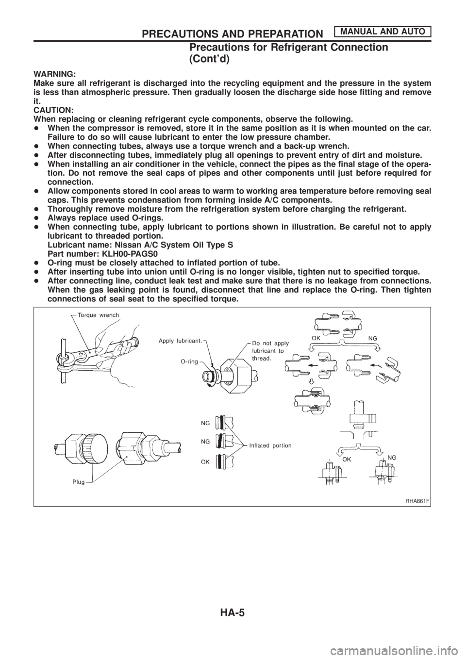
+When connecting tube, apply lubricant to portions shown in illustration. Be careful not to apply
lubricant to threaded portion.
Lubricant name: Nissan A/C System Oil Type S
Part number: KLH00-PAGS0
+O-ring must be closely attached to in¯ated portion of tube.
+After inserting tube into union until O-ring is no longer visible, tighten nut to speci®ed torque.
+After connecting line, conduct leak test and make sure that there is no leakage from connections.
When the gas leaking point is found, disconnect that line and replace the O-ring. Then tighten
connections of seal seat to the speci®ed torque.
RHA861F
PRECAUTIONS AND PREPARATIONMANUAL AND AUTO
Precautions for Refrigerant Connection
(Cont'd)
HA-5